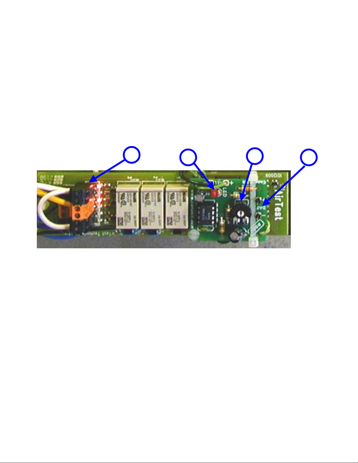
AirTest Model CN9000 Basic Input/Process Module Detail
This standard module incorporates a user wiring terminal block, trip point (TP) adjustment trimpots, TP output channel
selectors, a multi-colored LED status indicator and test points for connecting a Digital Volt Meter (DVM).
(1) – Wiring Terminal Block
A screw-less wiring terminal block provides connections for sensor power and 4-20 mA input. Two power sources,
typically 12-14 VDC and 24 VAC, are supplied for systems with mixed sensor types including loop powered
electrochemical sensors, 3 wire DC powered MOS or Catalytic bead sensors and 24 VAC powered IR CO2 sensors.
The power supplied to the terminals can be factory configured to many other standard or custom voltages. Refer to
Input/Output wiring for system specific details.
(2) – Input Signal Test Points
The 4-20mA input is terminated with a 100 ohm, 1% precision, current sensing resistor. To read the signal current of the
attached sensor connect the negative lead of a DVM (Digital Volt Meter) to the black ring terminal test point (common
ground reference) and connect the positive lead to the bare lead on the top of the current sense resistor. The use of small
alligator or flee clips is recommended. Multiply the voltage reading is by 10 to calculate the milliamp reading. For
example a reading of 0.40 volts would be 4mA. (0.40 x 10 = 4). Twenty milliamps would read as 2 volts on the DVM.
(2.00 x 10 = 20)
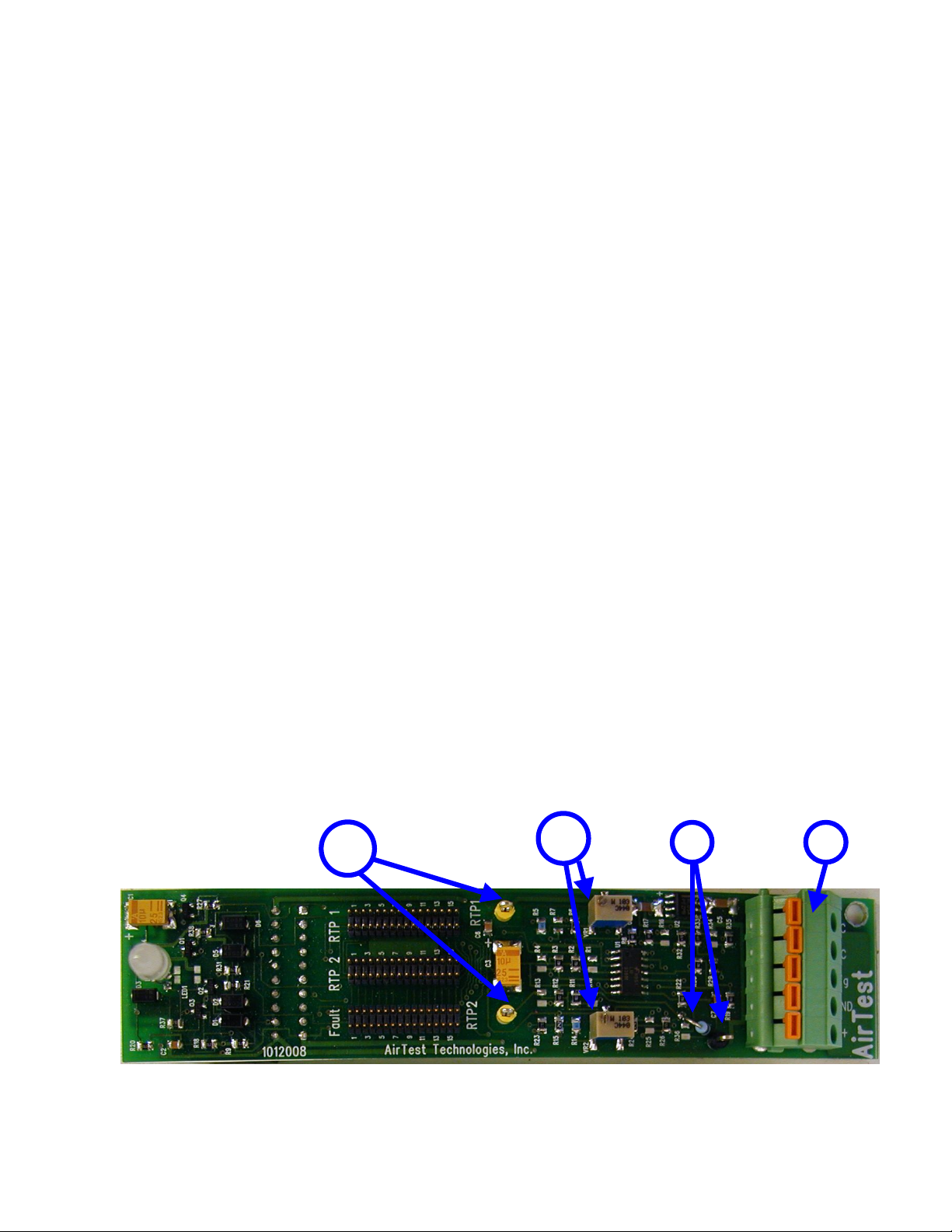
(3) – Relay Trip Point (RTP) adjustments and test points.
The standard input/process module incorporates 4 comparator circuits where 2 have user settable relay trip points or TP’s
for short. A TP is the point where a comparators single bit output changes to an active or inactive state when the rising or
falling sensor signal level passes a threshold level.
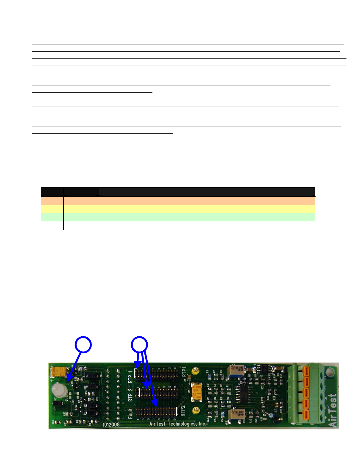
The voltage across the 100 ohm current sensing resistor is compared to a reference voltage. If the current sense voltage
level is higher than the reference voltage, the output signal of the comparator circuit is activated and will be available on
its’ Output Channel selector jumper block. Two comparators are used for sensor fault detection and have factory set TP
levels. See System specifications for more detail. These comparator outputs are combined and output to a single “FAIL”
channel selector.
The 2 remaining comparators have user adjustable TP’s through the turning of potentiometer screws (see 3a below). The
TP level for TP1 and TP2 can be read at yellow test points (see 3b below). In the image below, TP1’s yellow ring terminal
test point and level adjust potentiometer is located at the top of the board and is identified by the white lettering printed on
the circuit board, just to the left of the test terminal.
NOTE – Since a module can be plugged into the interconnect board on the left or right, the lettering and component
positions will be inverted to the images shown.
A TP’s voltage level can be read at it’s corresponding test point and be converted to a current level as described above.
To set a TP1 of 12mA connect the negative lead to the black common ground reference test point near the current
sensing resistor and set the voltage read at TP1 test point to 1.20 volts. (12mA / 10 = 1.20 volts)
NOTE – For correct operation of status indicator TP1 voltage level must be set lower than TP2 voltage level.