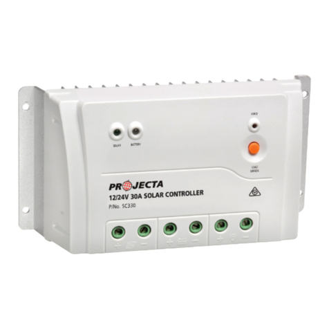
Projecta SC030 User manual

12 VOLT 30 AMP AUTOMATIC
P/No. SC030
SOLAR CHARGE CONTROLLER

IMPORTANT SAFETY INFORMATION
Please read this manual thoroughly before use and store in a safe place for future reference.
WARNING
• Please read these instructions completely prior to installation.
• Lead acid batteries can be dangerous. Ensure no sparks or flames are present when
working near batteries. Eye protection should be used. If mounting on a vehicle follow
all manufacturers’ instructions.
• Given sufficient light solar panels always generate energy even when they are
disconnected. Accidental ‘shorting’ of the terminals or wiring can result in sparks
causing personal injury or a fire hazard. It is recommended to cover the front face
of the panel(s) with a soft cloth to block incoming light during installation.
• For use with 12V (nominal) solar panels.
• For indoor, out of weather use only.
• Do not exceed the total limit of the solar controller (360W/30A)
FEATURES
3 STAGE CHARGING
Ideal for deep cycle batteries the SC030 delivers 3 stage charging, maximising battery life
and performance.
• Maintains your battery ready for use
• Safe to leave permanently connected
• Prevents solar over-charge/discharge
LCD DISPLAY
Monitor your power system from the LCD display including charge rate and battery
voltage levels.
BATTERY CHEMISTRY SELECTION
Suitable for automotive, deep cycle and Gel batteries, select Gel or Wet modes for improved
charging results.
ELECTRICAL PROTECTION
• Short circuit & over current protection
• Reverse polarity protection
2

PRODUCT OVERVIEW
SPECIFICATIONS
3
Type Automatic
Input 12V Solar Panel
Maximum Input 25V DC, 30A
Battery 12V
Maximum Panel Size 360W
Size (mm) 181 x 104 x 47
Approvals EMC
Charge Control 3 Stage Charging Wet Gel
Bulk: 14.4 14.1
Absorption: 14.4 14.1
Float: 13.7 13.7
Maximum charging current 30 amps
Current Consumption when connected to Maximum 35mA
15 volt array (battery not present)
Current consumption when connected to Maximum 25mA
a 12 volt battery (array not present)
BATTERY CONDITION DISPLAY:
LED light indicated range
LOW (red) <11.5 +/-0.4
FAIR (yellow) 11.5 to 12.5 +/-0.4
GOOD (green) >12.5+/-0.4
LCD Meter Accuracy DC voltage 1.25%
LCD Meter Accuracy DC current 3%
PROTECTION:
Over temperature protection engages at >80°C (176°F)
(stop charging)
Over temperature protection resets at <65°C (149°F)
(restart charging)
Operation Temperature from -5° to 50°C (23° to 122°F)
Storage Temperature from -10° to 70° C (14° to 158°F)
Operation Humidity Range 0 to 80% RH
Battery charging status
L.E.D indicators Voltage & AMPs display
Battery type
selection
LCD display
Mounting holes
Battery charge level
L.E.D indicators

4
INSTALLATION
The charge controller is designed to be mounted flush with the wall. Flush mounting
requires a rectangular cutout in the mounting surface with sufficient space (50–75mm)
depth behind, to accommodate the controller and wiring. The charge controller may
also be mounted to the wall without making a cutout. This is the quickest and easiest
mounting procedure, however, the controller will be raised from the wall.
WIRING DIAGRAM
Connection Procedures (please refer to the connection diagram above)
1. Once the controller has been properly mounted select either Gel or Wet modes on the unit.
2. Connect the solar panel positive side to the charge controller “ARRAY” positive (+)
with a suitable wire. Be careful not to short circuit the solar array.
3. Connect the solar panel negative side to the charge controller “ARRAY” negative (-)
with a suitable wire.
4. Connect the battery positive side to the charge controller “BATTERY” positive (+)
with a suitable wire.
5. Connect the battery negative side to the charge controller “BATTERY” negative (-)
with a suitable wire.
164mm

5
Please pay close attention to the following wire specifications
WIRE SIZE
Refer to the “WIRE SIZE” chart below to determine the minimum size wire needed for
each connection. When using heavy stranded wire, you may need to divide the ends into
two groups and straddle the screw on the terminal block.
WIRE SIZE – INSTALLATION
NOTE: Any variation of wire size or length will affect the performance of the charge
controller.
OPERATION
Once properly mounted and connected, the charge controller will start charging
immediately given adequate solar power. The 12 Volt 30 Amp Solar Charge Controller is
based on a three stage charging algorithm; Bulk Charge Mode, Constant Voltage Mode
and Float Mode.
Battery condition is indicated by the LED lights. The controller will indicate the battery
condition in three states: GOOD (green), FAIR (yellow), LOW (red). Please refer to label.
Please note the charge controller is not able to start the charging process if the initial
battery voltage is less than 3 volts (+/- 0.3).
CHARGING STATUS INDICATOR L.E.Ds
The top 3 LED indicator lights show the charging status of the charge controller.
The red LED indicates solar power available.
ON: indicates solar panel properly connected and solar power supplied within parameters
OFF: indicates no power available or insufficient voltage to activate controller.
The blue LED indicates the charge controller is in “Bulk Charge or absorption” mode.
The green LED indicates “Charge Complete” which means the battery is fully charged and
the charge controller is in float mode
Battery to Controller Wire Solar Array to Controller Wire Size/Distance
Size/Distance
Length of Wire Up to 3 metres 6m 9m 12m
Wire Size 14mm2(6 B&S) 4.58mm28mm214mm2
(10 B&S) (8 B&S) (6 B&S)

Status Bulk Charge Charge Complete
LED (BLUE) LED (GREEN) Conditions
Bulk Charge ON OFF Indicates the battery is charging.
Power is being allowed to pass through
to the battery.
Solar Power Flashes OFF Indicates the solar panel voltage
Weak is too low when in Bulk Charge mode or
insufficient sunlight.
Float Charge OFF ON Indicates fully charged battery and a small
Mode charge will continue to pass to the battery
in order to maintain a full charge state.
6
BATTERY CHARGE LEVEL INDICATOR L.E.Ds
The bottom 3 LED indicator lights show the batteries level of charge.
The green LED indicates the battery voltage is greater than 12.5V.
The yellow LED indicates the battery voltage is between 11.5V and 12.5V.
The red LED indicates the battery voltage is less than 11.5V.
The red LED will blink if battery is disconnected from the unit. The charge controller will
not function if not connected to both the battery as well as the solar array. Testing may not
be performed while the charge connector is unhooked from one or both of the batteries or
solar array.
When Solar Power is weak as well as during the night the charger will turn off the
charging LED.
MAINTENANCE
The following maintenance is recommended to be performed every three months:
1. Ensure all wire connections are sound and free from corrosion. Tighten terminal block screws
for both the solar array as well as the battery terminals.
2. Visually check the solar array and battery wiring for signs of overheating, damage, and
cracking. Replace any wires showing wear with new wires of the same gauge.
3. Verify each LED status to ensure match with specifications using a voltmeter.

7
FREQUENTLY ASKED QUESTIONS
Q. Why wont my battery charge?
A. Solar panel may be sized incorrectly. A panel with a larger output is required. You may add
on to existing panels by wiring the additional in parallel with the existing panel.
Usage may be too high. The battery is being drawn upon at a faster rate than the panel
is able to produce. A secondary battery may be used, by physically switching the batteries
out and allowing one battery to supply power while the other is being charged.
Battery may be too small. In this case it may appear the battery is not charging however
it is the reserve that is depleting too quickly. A battery with a larger capacity may be
required. A secondary battery may be used, either by physically switching the batteries
out and allowing one battery to supply power while the other is being charged or using a
battery isolator. A second battery may also be added to the existing battery by wiring the
additional battery in parallel to the existing battery. The charge controller only needs to be
connected to one of the batteries in this case.
The battery may be bad. Small level of charge or discharge will greatly affect the battery
voltage. Battery needs replacing.
Wires may be incorrectly hooked to the charge controller. Ensure the wires are connected
in parallel to the controller and to the correct terminals.
Q. Why does my solar panel have no output?
• The solar panel may be seriously affected by the angle of the panel with regards to the
sun, and environmental factors. Ensure the surface is clean and free of dust and build
up. A clean, damp rag may be used to clear the panel of dust. Do not use soap or
solvents of any kind. Cloudy conditions will affect the output of the solar panel.
• Wires may be incorrectly hooked to the charge controller. Ensure the wires are
connected in parallel to the controller and to the correct terminals. Please refer to the
Connection Procedures portion of this manual.

WARRANTY STATEMENT
Applicable only to product sold in Australia
Brown & Watson International Pty Ltd of 1500 Ferntree Gully Road, Knoxfield, Vic.,
telephone (03) 9730 6000, fax (03) 9730 6050, warrants that all products described in
its current catalogue (save and except for all bulbs and lenses whether made of glass or
some other substance) will under normal use and service be free of failures in material
and workmanship for a period of one (1) year (unless this period has been extended as
indicated elsewhere) from the date of the original purchase by the consumer as marked
on the invoice. This warranty does not cover ordinary wear and tear, abuse, alteration of
products or damage caused by the consumer.
To make a warranty claim the consumer must deliver the product at their cost to the
original place of purchase or to any other place which may be nominated by either BWI or
the retailer from where the product was bought in order that a warranty assessment may
be performed. The consumer must also deliver the original invoice evidencing the date and
place of purchase together with an explanation in writing as to the nature of the claim.
In the event that the claim is determined to be for a minor failure of the product then
BWI reserves the right to repair or replace it at its discretion. In the event that a major
failure is determined the consumer will be entitled to a replacement or a refund as well as
compensation for any other reasonably foreseeable loss or damage.
This warranty is in addition to any other rights or remedies that the consumer may have
under State or Federal legislation.
IMPORTANT NOTE
Our goods come with guarantees that cannot be excluded under the Australian Consumer
Law. You are entitled to a replacement or refund for a major failure and compensation for
any other reasonably foreseeable loss or damage. You are also entitled to have the goods
repaired or replaced if the goods fail to be of acceptable quality and the failure does not
amount to a major failure.
Distributed by
AUSTRALIA
Brown & Watson International Pty Ltd
Knoxfield, Victoria 3180
Telephone (03) 9730 6000
Facsimile (03) 9730 6050
National Toll Free 1800 113 443
NEW ZEALAND
Narva New Zealand Ltd
22–24 Olive Road
PO Box 12556 Penrose
Auckland, New Zealand
Telephone (09) 525 4575
Facsimile (09) 579 1192 IS267
Issue 1 11.12.13
Table of contents
Other Projecta Controllers manuals
