manuals.online logo
Brands
  1. Home
  2. •
  3. Brands
  4. •
  5. Airwell
  6. •
  7. Heat Pump
  8. •
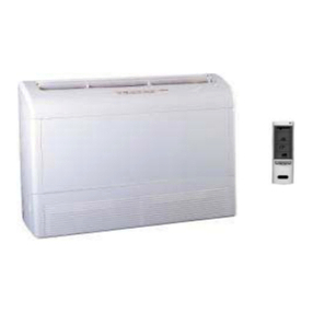
  9. Airwell SX 12 RCC User manual

Airwell SX 12 RCC User manual

Split system for Wall / Ceiling mounting
Comfort Range
Heatpump
GB
INSTALLATION INSTRUCTION TH 3990012/06
Read this instruction sheet carefully before installing, retain it safely for future reference.
SX 16 RCC
18 RCC
24 RCC
30 RCC
Read this instruction sheet carefully before installing, retain it safely for future reference.
12 RCC
MANUAL MENU
SX
Split system for wall / ceiling mounting
MANUAL MENU
2
GENERAL RECOMMENDATIONS
- Congratulations for having selected an
ELECTRA air conditioner.
SAFETY DIRECTIONS
- Follow the safety rules in force when you
are working on your appliance.
- Installation and maintenance of the
equipment must only be performed by
qualified specialists in accordance with the
rules of good workmanship and prevailing
standards and instructions.
- Make sure that the power supply and its
frequency are adapted to the required
electric current of operation, taking into
account specific conditions of the location
and the current required for any other
appliance connected with the same circuit.
WARNING
- Cutoff power supply before starting to work
on the appliance.
- The manufacturer declines any
responsibility and the warranty becomes
void if these instructions are not respected.
- If you meet a problem, please call the
Technical Department of your area.
- If possible, assemble the mandatory or
optional accessories before placing the
appliance on its final location.(see instruc-
tions provided with each accessory)
- In order to become fully familiar with the
appliance, we suggest to read also our
Technical Instructions .
- The information contained in these Instruc-
tions are subject to modification without
advance notice.
IT IS MANDATYORY TO
CUTOFF POWER SUPPLY
BEFORE STARTING TO
WORK IN THE ELECTRIC
CASING BOXES.
SX
Split system for wall / ceiling mounting
MANUAL MENU
4
CONTENTS OF PARCEL
1 PXD.
1 wall support. (supplied fitted to the unit).
1 bag containing hardware.
1 bag containing documentation.
1 IR remote control + support.
1 template for positioning connection tubing.
+ connection tubing fixing clamps
1 assembly template (distance between
mounting holes)
1 sensor connecting cable
1 active charcoal filter and its support
SUMMARY
DESCRIPTION
Dimensions of Indoor Units ........................ 4
Dimensions of Outdoor Units ..................... 5
INSTALLATION
Location of the Indoor Unit ...................... 6-7
Location of the Outdoor Unit ...................... 8
Refrigerant Line ..................................... 9-11
Installation ........................................... 12-16
Coolant specifications ......................... 17-18
Electrical Connections......................... 19-23
MAINTENANCE
Scheduled Maintenance ...................... 24-26
SX
Split system for wall / ceiling mounting
MANUAL MENU
5
630
A
MODEL 12 - 16- 18
A = 820mm
MODEL 24 - 30
A = 1200mm
DIMENSIONS OF INDOOR UNIT
SX
Split system for wall / ceiling mounting
MANUAL MENU
200
100 MIN
WALL
WALL
1000 MIN
WALL
MIN
800
WALL
MIN
MINIMUM CLEARANCE
500 MIN FROM TOP
835
865
FRONT VIEW
WIRING
CONNECTIONS
SUCTION
PIPE (FLARED)
LIQUID
PIPE (FLARED)
RIGHT VIEW
TOP VIEW
378
340
950
527
AIR INTAKE
AIR OUTLET
25
100
220
236
260
88.5
58
WIRING
CONNECTIONS
SUCTION TUBE
(FLARED)
LIQUID TUBE
(FLARED)
VALVE
CONNECTIONS
AIR INTAKE
AIR OUTLET
237
50 100 MIN
WALL
MINIMUM CLEARANCE
800 MIN
WALL
WALL
100
400
MIN
WALL
500 MIN FROM TOP
760
544
472 58
48
15
300
325
370
WIRING
CONNECTIONS
103
90
75
MINIMUM CLEARANCE
150 MIN
WALL
800 MIN
WALL
WALL
150
400
MIN
WALL
500 MIN FROM TOP
845
690
545
490
302
350
151.5 151.5
15
AIR INTAKE
AIR OUTLET
330
50
300
325
SX
Split system for wall / ceiling mounting
GC12RCC
GC16RCC
GC18RCC-S
GC24RCC-S
GC30RCC
6
MANUAL MENU
7
80 mm
900 mm
200 mm
RH and LH outputs of
Condensate output in the
50 mm:
ceiling mounted
20 mm:
wall mounted
Connection to the SX to
be MANDATORILY insulated
RH output
condensate recovery tray
case of a ceiling mounted unit
INSTALLATION OFTHE SX
INDOOR UNIT
- Install the wall support of the SX using the
installation template supplied with the unit
-The cut-outs for the unit are shown on this
template.
- Reminder of MINIMUM clearances to be
provided.
- Coolant connections can be made on the
LH side, on the RH side or at the rear.
- Condensate evacuation possibilities: right,
left, rear and front in the case of a ceiling
mounted unit. (2 condensate outputs are
available on the recovery tray).
LH output
Output to rear
SX
Split system for wall / ceiling mounting
MANUAL MENU
8
INSTALLATION
- Remove the wall support mounted at the rear
of your SX
- To install the wall support, locate the
template in order to observe the correct
distance between mounting holes marked on it.
CAUTION - be careful with the condensate
evacuation point:
After determining the outlet for the
condensateevacuation (LH, RH,rear), make
sure that the wall mounting is installed with
a slope which favours this evacuation.
-Secure the wall support with 4 screws (not
supplied)
Mounting holes for wall installation
Location of threaded rods (Dia 8 mm max.)
for ceiling installation
Condensates evacuation
-Take care to install unit with a positive
slop for condensate drainage
SX
Split system for wall / ceiling mounting
MANUAL MENU
9


A
B
C
D
B
D
B
A
D
C
100 mm*
100 mm*
400 mm*
500 mm*
500 mm*
100mm
E
E
150 mm*
150 mm*
400 mm*
500 mm*
500 mm*
GC12-16 18-24-30
Terminali di montaggio x 4
SUSPENDED
*minimum
1)Hole Ø 17 mm
2)Condensate drain
connector (accesory) Ø 16 mm
INSTALLATION OF THE OUTDOOR
UNIT
-Minimum clearance to respect (in mm).
Almohadillas de montaje x 4
Wall bracket
(not supplied)
CAUTION
If the heat pump outdoor unit is installed in
an area where the outdoor temperature may
fall below +1°C, it is mandatory to provide a
system preventing any risk of freezing of the
condensate (e.g. heating wire).
ONTHE FLOOR
Mounting pads x 4
DRAINING CONDENSATES
SX
Split system for wall / ceiling mounting
MANUAL MENU
10
GC12-16 H = 7m MAX*
GC18-24-30 H = 10m MAX
A
B
C
D
E
D
C
L. MAX
Höchstlänge
PXD L. (m)
12 RC 15
15-18-24-28-32 25
L . MAX
*without siphon
REFRIGERANT CONNECTIONS
A«Gaz»pipe
B«Liquid»pipe
CFlare nut
DPipe insulation (6 mm min.)
EInsulation sleeve
-The indoor unit may be installed above or
below the unit
-The flare couplings are available as
accessories in standard lengths of 2.5, 5 and
8 m.
-The pipes are delivered coiled and equipped
with flare nuts.
-Carefully uncoil the pipes in the opposite
direction from the turns so as not to flatten
them.
A
B
C
D
E
-Fit a siphon on the Gas line every 3m.
SX
Split system for wall / ceiling mounting
MANUAL MENU
11
GAS LIQUIDO/
LIQUID
R 60 MAXI
mm
R 20 MAXI
mm
90°
90°
150 ±5
70 ±5
110 ± 5
60 ± 5
Ø GAS tube Ø LIQUID tube
SX12 -161/2"1/4"
SX18 -24 5/8" 3/8"
SX30
1
2
3
Press fully home
All 4 must support the part
INSTALLATIONOF TUBINGON
WALL SUPPORT
-The main advantage of your PXD product is
thepossibility of locatingthe coolant tubing
on the wall support before installing the unit
(usingthetemplate supplied).
-Place the tube locating template on the wall
support.
INSTALLATIONOF TUBINGON
WALL SUPPORT
-After choosing your coolant tubing input
location (right, left or rear), you can set up
yourtubing. To dothis,use theinstallation
template in order to form the tubes correctly
and thus facilitate connection.
Recess for
FLARE nuts
Location of tubing clamps
Press
Slide under bracket
SX
Split system for wall / ceiling mounting
MANUAL MENU
12
5°
B
A
2
1
1
3
2
Insulated liquid tube
Insulated gas tube
INSTALLATIONOF TUBINGON
WALL SUPPORT
-Locate the LIQUID tube above the GAS
tube.
-Fit the nuts of the (formed) tubing into the
recess provided on the template.
-Secure the tubing with the clamps provided.
-Remove the tubing template; you can now
install your unit on its support.
NOTE
output to the rear
-The slanted hole prevents condensates or
rain from entering the unit.
-Fita Dia. 70 mmsleeveinto the hole.
AOutside
BInside
1DrillDia.70 mm
2Wall
Remove the template
Secure the tubing with the clamps provided
WARNING
The tubes must be closed to prevent
impurities from entering
SX
Split system for wall / ceiling mounting
MANUAL MENU
13
5
1
4*
32
2
5
4
INSTALLATION OF THE INDOOR
UNIT SX
-On the SX, remove:
The intake grid
The LH and RH side panels
Screws
FOR THE INTAKE GRID:
1Pull the grid forwards.
2Remove the two end screws.
3Unscrew the central screw, but do not
remove it completely.
4Unhook the grid.
FORTHESIDEPANELS:
5Remove the side panels (downward
movement)
*GOOD BAD
SX
Split system for wall / ceiling mounting
MANUAL MENU
14
INSTALLATION OF THE SX ON THE
WALL SUPPORT
-Refer to the diagram below, for installation
of the SX.
-Ceiling mounting (refer to the NOTE below).
Wall mounted
-For ceiling mounting, install the two clamp screws
(provided) for the unit on the support.
Ceiling mounted
SX
Split system for wall / ceiling mounting
MANUAL MENU
15
-In the case of a ceiling mounted installation
run the evacuation tube down along the
side panel and secure it with clamps as
shown below. Also break the preformed
cut out in the corner of the intake grid.
Tappo
Recipiente di recupero delle condense
Tubo di scarico
Tubo LIQUIDO
LIQUID tube
Tubo GAS
CONNECTION OF CONDENSATE
EVACUATION TUBE
-Water condensation must be evacuated
directly to the outside; observe an
appropriate slope for the evacuation duct,
which should slope downwards in the case
of a connection to the wastewater system
(2.5 cm/m slope).
- AnS-bendmust be installed onthe
evacuationduct, below thelevelof the
recovery tray of the unit.
-Provide insulation for the evacuation tube
inthe case ofarisk offreezingor condensation.
- Evacuation with pump kit: (refer to
tions provided with kit).
- The unit is supplied with an evacuation tube
- The right and left outlets are blocked off by
a plug. Do not forget to remove this plug
before connecting the evacuation tube.
Tapón
Bandeja de recuperación de condensados
Tubo de evacuación
Tubo de LÍQUIDO
Tubo de GAS
GAS tube
Evacuation tube
Plug
-
Condensate recovery tray
SX
Split system for wall / ceiling mounting
MANUAL MENU
16
-Only the outdoor unit is charged with R22
cooling fluid. The indoor unit contains a small
quantity of a neutral gas. This the reason it
isimperativetovacuum the linking pipes and
the indoor unit.
ASSEMBLY
-The outdoor unit is equipped with a valve
allowing to vacuum the installation (large
valve)
1Connect the connecting pipes to the outdoor
unit by FLARE NUTS and to the indoor unit by BRAZING
-To obtain the right tightening, cover the sur-
face with cooling oil.
-The use of a counter wrench is required to
tighten the valves.
-The values of the tightening torque are
shown in the table below.
Ø of the pipe Torque
Pipe 1 / 4”15-20 Nm
Pipe 3 / 8”30-35 Nm
Pipe 1 / 2 “50-54 Nm
Pipe 5 / 8”70-75 Nm
Pipe 7 / 8 “90-95 Nm
2Connect the vacuum pump with the flare
coupling of the outdoor unit equipped with a
process valve.
3Start the vacuum pump and check that the
needle of the indicator goes down to - 0,2
mm Hg.
The pump should run during at least 15 mi-
nutes.
4Before disconnecting the vacuum pump,
check that the vacuum indicator remains in
the same position during five minutes.
5Disconnect the vacuum pump.
6 Remove the cap of the "GAS" and "LIQUID"
valves and open them with a hexagonal
wrench to free the R22 contained in the
outdoor unit.
7If the length of the refrigerant pipes of one
line exceeds 4m, add the extra charge
indicated in the table B page 18.
Certainunitsrequire an additional charge
as per Table A page 17.
8 Check that the linking pipes are sealed. Use
an electronic leak detector or a soapy
sponge.
VACUUM OF COOLING PIPES
AND INDOOR UNIT
SX
Split system for wall / ceiling mounting
MANUAL MENU
17
SNOITACIFICEPS
EBUTSAGØebuT
"2/1"2/1"8/5"8/5"8/5
EBUTDIUQILØebuT
"4/1"4/1"8/3"8/3"8/3
egatlovylppusCAV032~V032~V032~V004~N3V004~N3/V032~
tinuedistuoniegrahC
)degrahcyrotcaf(
m4rof
CGpmuptaeH
ebotegrahc22R
etisehtnodeddaledompmuptaeH
COOLING SPECIFICATIONS
SX12 SX16 SX18 SX24 SX30
1220 g 1240 g 1770 g 1730 g
V032~ V004~N3
1670 g 1810 g 2405 g
40 g 170 g 0 g 0 g 165 g
TABLE A
SX
Split system for wall / ceiling mounting
MANUAL MENU
18
m5srg5srg51srg0
m6srg01srg03srg0
m7srg51srg54srg0
m8srg02srg06srg04
m9srg16srg57srg80
m01 srg07 srg09 srg021
m11 srg97 srg501 srg061
m21 srg88 srg021 srg002
m31 srg79 srg531 srg042
m41 srg601 srg051 srg082
m51 srg511 srg561 srg023
m61 srg081 srg063
m71 srg591 srg004
m81 srg012 srg044
m91 srg522 srg084
m02 srg042 srg025
m12 srg552 srg065
m22 srg072 srg006
m32 srg582 srg046
m42 srg003 srg086
m52 srg513 srg027
LENGTH OF CONNECTIONS
TABLE B
-R22 charge dependent of length of coolant connections
Cooling only and Heatpump model
Example: (only applicable for a flare installation)
Installation of a heatpump SX 16 with 15 m of coolant connections:
TableA + Table B = Add 40 g + 70 g of R22 on the work-site.
SX12 SX16 SX18 - 24
srg71
srg43
srg15
srg86
srg58
srg201
srg911
srg631
srg351
srg071
srg781
srg402
srg122
srg832
srg552
srg272
srg982
srg603
srg323
srg043
srg753
Sx30
SX
Split system for wall / ceiling mounting
MANUAL MENU
Your unit is configured for HEAT PUMP:
Disconnection the 4.7k resistor and
connect the sensor wire supplied.
To configure for COOLING ONLY:
Remove the RC marked MODEL PLUG and
replace with ST marked MODEL PLUG
(mounted on the electronic circuit board).
MODEL PLUG
SX
Split system for wall / ceiling mounting
ELECTRICAL CONNECTIONS
MANUAL MENU
20
SX
Split system for wall / ceiling mounting
Standard
* Factory configuration
Estándar
Heat / Cool (without auto Cool / Heat mode)
Heat / Cool (all modes available)
Auto Cool / Heat mode or fan mode
RESET LIGHT
RC-4 (RCL)
P/N 436670
Batteries : 2 x 1.5V
Size : AAA, LR03, AMG
SET
CLR
HOUR
CONFIGURATION OF REMOTE
CONTROL
To change the configuration:
1 - Remove the batteries.
2 - Set the switches.
3-MANDATORILY perform a RESET(see
below).
4 - Reinstall the batteries.
RESET FUNCTION:
1)Remove one battery.
2)Simultaneously press these 4 keys until
the symbols are no longer displayed.
3)Reinstall the battery.
The four keys to be pressed are:
Location of configuration switches.
Location of RESET button.
MANUAL MENU

This manual suits for next models

4

Other Airwell Heat Pump manuals

Airwell PAC HT Series User manual

Airwell

Airwell PAC HT Series User manual

Airwell CKD Series User manual

Airwell

Airwell CKD Series User manual

Airwell WELLEA WT RCW30 User manual

Airwell

Airwell WELLEA WT RCW30 User manual

Airwell AWSI YIFA060-H13 User manual

Airwell

Airwell AWSI YIFA060-H13 User manual

Airwell Aqu@Scop ADV 006 Reference guide

Airwell

Airwell Aqu@Scop ADV 006 Reference guide

Airwell KXL DCI Series User manual

Airwell

Airwell KXL DCI Series User manual

Airwell HRW Series Manual

Airwell

Airwell HRW Series Manual

Airwell CW-AR Manual

Airwell

Airwell CW-AR Manual

Airwell XLM9 Manual

Airwell

Airwell XLM9 Manual

Airwell HRW 019 Manual

Airwell

Airwell HRW 019 Manual

Airwell Monobloc R32 Installation instructions

Airwell

Airwell Monobloc R32 Installation instructions

Airwell PNX 30 DCI User manual

Airwell

Airwell PNX 30 DCI User manual

Airwell AQL20-75 Manual

Airwell

Airwell AQL20-75 Manual

Airwell GC 30 DCI User manual

Airwell

Airwell GC 30 DCI User manual

Airwell AW-XDO009-H11 User manual

Airwell

Airwell AW-XDO009-H11 User manual

Airwell Monobloc R32 User manual

Airwell

Airwell Monobloc R32 User manual

Airwell Wellea Mono User manual

Airwell

Airwell Wellea Mono User manual

Airwell AWSI-DED076-N11 User manual

Airwell

Airwell AWSI-DED076-N11 User manual

Airwell Aqu@Scop HT SPLIT 12-6 User manual

Airwell

Airwell Aqu@Scop HT SPLIT 12-6 User manual

Airwell DLS 18 User manual

Airwell

Airwell DLS 18 User manual

Airwell FLO 9 DC INV User manual

Airwell

Airwell FLO 9 DC INV User manual

Airwell WELLEA MONO SPLIT A R32 User manual

Airwell

Airwell WELLEA MONO SPLIT A R32 User manual

Airwell Aqu@Scop Advance R410A User manual

Airwell

Airwell Aqu@Scop Advance R410A User manual

Airwell LWM8-1P User manual

Airwell

Airwell LWM8-1P User manual

Popular Heat Pump manuals by other brands

Mitsubishi Electric CAHV-P500YB-HPB Service handbook

Mitsubishi Electric

Mitsubishi Electric CAHV-P500YB-HPB Service handbook

Trane 4TWR4 Use and care

Trane

Trane 4TWR4 Use and care

OSO HOTWATER Optima OGC 300 installation manual

OSO HOTWATER

OSO HOTWATER Optima OGC 300 installation manual

Carrier 50XZ024 manual

Carrier

Carrier 50XZ024 manual

Carrier 50EZ Owner's information manual

Carrier

Carrier 50EZ Owner's information manual

JBG HT ZHHS-01-10K-R290-V5-M Service manual

JBG HT

JBG HT ZHHS-01-10K-R290-V5-M Service manual

Bitzer KB-200-1 operating instructions

Bitzer

Bitzer KB-200-1 operating instructions

Trane 5TWX5 Installation and operation manual

Trane

Trane 5TWX5 Installation and operation manual

Green Energy ANTEK AIR MAGNA 100 Installation and maintenance manual

Green Energy

Green Energy ANTEK AIR MAGNA 100 Installation and maintenance manual

STIEBEL ELTRON WWK 220 electronic Operation and installation

STIEBEL ELTRON

STIEBEL ELTRON WWK 220 electronic Operation and installation

Carrier 38AJ 008 Installation, operation and maintenance instructions

Carrier

Carrier 38AJ 008 Installation, operation and maintenance instructions

WATERKOTTE Basic Line BS 7010 Planning and installation guide

WATERKOTTE

WATERKOTTE Basic Line BS 7010 Planning and installation guide

Polar Air VTAC Installation, operation & service manual

Polar Air

Polar Air VTAC Installation, operation & service manual

Bryant 547K 04-07 Series Service and maintenance instructions

Bryant

Bryant 547K 04-07 Series Service and maintenance instructions

American Standard 4A6H6036 Installer's guide

American Standard

American Standard 4A6H6036 Installer's guide

HIdRos LZT P2U Series Technical manual

HIdRos

HIdRos LZT P2U Series Technical manual

Bard 8620-343 Supplemental instructions

Bard

Bard 8620-343 Supplemental instructions

Gorenje TC 80 Z engineering data

Gorenje

Gorenje TC 80 Z engineering data

manuals.online logo
manuals.online logoBrands
  • About & Mission
  • Contact us
  • Privacy Policy
  • Terms and Conditions

Copyright 2025 Manuals.Online. All Rights Reserved.