Airwell Evaporative ES002 User manual

AIRWELL GROUP PTY LTD | 30 Harris Rd, Malaga WA 6090 | P: +61 8 9209 2666 | www.airwellgroup.com.au
Evaporative pump ES002
INSTALLATION & OPERATIONS MANUAL

DESIGNED AND MANUFACTURED IN AUSTRALIA
A.B.N. 46 009 323 871
30 Harris Road, Malaga, Western Australia 6090
Tel: (61) 08 9209 3355 - Fax: (61) 08 9209 2666
Email: sales@airwellgroup.com.au
http://www.airwellgroup.com.au
Read this manual
Carefully read this manual before commissioning or servicing the product.
Notes:
-This documentation is part of the product.
-Retain the documentation during the entire service life of the product.
-Pass on the documentation to any subsequent user.
-Ensure that any supplement to this documentation is included, if necessary.
The contents and specifications herein are subject to change without notice. All rights reserved.

pumping solutions for all applications | www.airwellgroup.com.au
MAN_5501
Revision: 7.0
Status: Approved
Issue Date: 08/06/2021
Page 2 of 26
Airwell Group Pty Ltd | Evaporative pump ES0023
1INTRODUCTION..............................................................................................................................2
1.1 Pump specifications ............................................................................................................. 2
1.2 How the airwell pump works ............................................................................................... 3
2TOOLS REQUIRED FOR THIS JOB.....................................................................................................4
3SAFETY ...........................................................................................................................................5
4WHAT IS IN THE PACKAGE..............................................................................................................6
5ASSEMBLY AND INSTALLATION......................................................................................................9
6CORROSION FACTORS..................................................................................................................15
7MAINTENANCE ............................................................................................................................16
7.1 Purging the pump –Method A........................................................................................... 17
7.1 Purging the pump –Method B ........................................................................................... 17
7.2 Depressurising the system ................................................................................................. 18
7.3 Removal of pump for service ............................................................................................. 18
7.4 Cleaning the probes ........................................................................................................... 19
8DRAWINGS...................................................................................................................................21
9TORQUE SETTINGS.......................................................................................................................24
10 WARRANTY DETAILS ....................................................................................................................25
11 WARRANTY REGISTRATION CARD................................................................................................26
1INTRODUCTION
The purpose of the evaporative pump ES002 is to assist and accelerate the evaporating procedure of leachate
ponds.
This manual covers the installation, operation, maintenance, servicing and troubleshooting of the ES002 pump.
1.1 Pump specifications
Diameter
8”
Ø219mm
Weight
154kg
Nominal length
2.5m
Actual length
2.7m
Displacement
95Lit

pumping solutions for all applications | www.airwellgroup.com.au
MAN_5501
Revision: 7.0
Status: Approved
Issue Date: 08/06/2021
Page 3 of 26
Airwell Group Pty Ltd | Evaporative pump ES0023
1.2 How the airwell pump works
Compressed air is a particularly useful means of transferring energy to pump water. Air compressed at an existing
power source can be carried significant distances through MDPE polyethylene pipe with limited loss of pressure,
saving a costly power installation to the water source, whilst allowing the compressor to be used for multiple
pumps, or other local purposes.
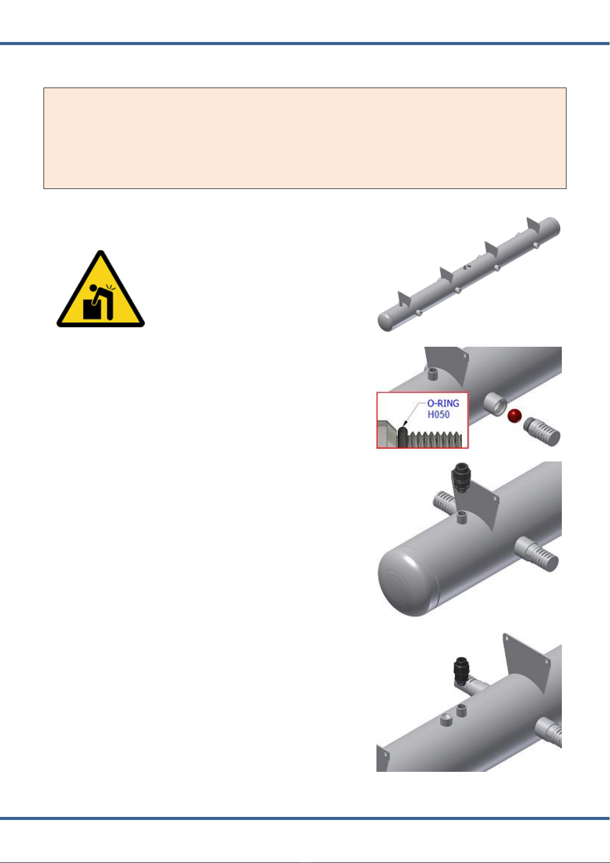
The Airwell pump component is a 316L grade stainless steel tube that can be manufactured in varying forms and
sizes to suit a variety of different applications. The tube is enclosed at each end and incorporates a foot valve(s) to
allow the submerged vessel to fill with water and a check valve on the outlet preventing the return of the
expelled water. The valves are our own design and incorporate special features to provide exceptional ability to
handle silt and sand, whilst keeping a very simple, maintenance free construction. The clean, hard valve seats
provided for the polyurethane balls to close on are kept clean by the circulation of the water and are raised above
the bottom of the pump to minimise contamination.
Within our most popular pumps there are two level (conductivity) probes; one long enough to reach the bottom
of the pump to detect when the pump is empty, and one short one to detect when it’s full. This is the key to the
automatic function of the pump. We use the conductivity of water to monitor the high and low fluid levels in the
pump. This means that a ‘contact’ is made when the water rises to the height of the short probe at the top of the
vessel, (now both probes are wet) and is ‘broken’ when the water level falls below the lower probe at the bottom
of the pump, (when both probes are dry).
An electronic circuit in the control unit detects this making and breaking of water contact, and subsequently
changes the state of a 3-way solenoid valve, allowing compressed air to the pump when a ‘full’ signal is received,
forcing the water up the discharge pipe, and then exhausting the air pressure to allow the pump to refill when the
‘empty’ signal is seen. The result of this is that the Airwell Pump will only cycle when a 'full' or 'empty' signal is
received, regardless of this being every few seconds, minutes, hours, weeks or years.
The control unit is located close to the pump, but above water level. Besides carrying the 3-way valve for the air
and the electronic control circuit, it also houses a 4.5 Amp/hour dry cell battery to power the system, which in
turn is recharged by the solar panel on the lid of the controller. Mains powered systems are available for those
applications where power is close to the water source, as are multiple pump controllers, flow monitoring and flow
control options.
It should be noted that the solenoid valve is a ‘latching’ type valve and requires a short pulse of power (60
milliseconds) in one direction to change state and will stay that way until a pulse in the opposite direction
changes it. A conventional solenoid requires permanent energisation to maintain either an open or closed state.
Should power be lost to the microprocessor, upon reconnection, the system will initialise on pressure, expelling
any water in the pump, and regaining a reference for the controller. The water delivered by an Airwell system
comes in surges, not a continuous flow like that of most electric pumps. Flow rates from the Airwell pump vary
dependant on many factors.

pumping solutions for all applications | www.airwellgroup.com.au
MAN_5501
Revision: 7.0
Status: Approved
Issue Date: 08/06/2021
Page 4 of 26
Airwell Group Pty Ltd | Evaporative pump ES0023
2TOOLS REQUIRED FOR THIS JOB
Spanners collection
or
Adjustable spanners
or
Socket wrench collection.
A pair of 1” pipe wrenches
Poly pipe cutter
Loctite 569 or PTFE tape for thread sealing
Grease for S/S threads

pumping solutions for all applications | www.airwellgroup.com.au
MAN_5501
Revision: 7.0
Status: Approved
Issue Date: 08/06/2021
Page 5 of 26
Airwell Group Pty Ltd | Evaporative pump ES0023
3SAFETY
Protective equipment required for this job:
Responsibilities of the person in charge:
-Identify the hazards that arise due to the special working conditions.
-Implement these hazards in the form of operating instructions.
-Specify clearly the responsibilities for the installation, operation, troubleshooting, maintenance and cleaning
of this equipment.
-Ensure all personnel is trained and informed about the dangers at regular intervals.
-Ensure that this equipment is always in technically perfect conditions.
Caution
Access to the equipment is only permitted to qualified persons or persons specially
trained by Airwell Group for this purpose.
Warning
This equipment is designed and constructed exclusively for the proper use described
in this manual.
Misuse of this equipment can cause dangerous situations.

pumping solutions for all applications | www.airwellgroup.com.au
MAN_5501
Revision: 7.0
Status: Approved
Issue Date: 08/06/2021
Page 6 of 26
Airwell Group Pty Ltd | Evaporative pump ES0023
4WHAT IS IN THE PACKAGE
In the package you should have received the following items:
1 x 70711100
Joiner Ø16 x Ø16
2 x 97724300
Poly end connector
Ø32 x 1"BSP(M)
1 x 7020021
Poly end connector
Ø20 x 1/2"BSP(M)
1 x 7020022
Poly end connector
Ø20 x 3/4"BSP(M)
4 x 97764300
Poly elbow
Ø32 x 1”BSP(F)
2 x 97734400
Poly tee Ø32
4 x 90433200
Poly reducing socket
1”BSP x 3/4"BSP
1 x AL1616PM[006]
Poly pipe Ø16 / PN16
(Airline)
1 x AL2020PM
Poly pipe Ø20 / PN20
(Airline)
4 x AL25PROPOL1200
Pro-Pol 1”BSP
2 x AL3216L
Poly pipe Ø32 / PN16
(Discharge line)
4 x AL3216L
Poly pipe Ø32 / PN16
(Discharge line)

pumping solutions for all applications | www.airwellgroup.com.au
MAN_5501
Revision: 7.0
Status: Approved
Issue Date: 08/06/2021
Page 7 of 26
Airwell Group Pty Ltd | Evaporative pump ES0023
4 x AL38PROPOL1200
Pro-Pol 1+1/2”BSP
1 x FA0089
Dam pump V3 standard
weld assy
1 x FA0146
Airline support bracket
8 x A035S
Screen assy –Dam pump
–SS
1 x A069SV
Probe holder assembly
8 x U044
Urethane solid ball Ø44
(red)
6 x M118
Poly float unit
4 x M609
Float bracket extension
4 x M116A
Float bracket
2 x M1104
Securing plate
1 x H302
Quick exhaust valve
1/2"BSP
1 x H134S
Bush (S/S)
1/2"BSP x 3/8”BSP
2 x M718B
Threaded rod (S/S)
M12 x 1.75
(L=225mm)
16 x H648
Screw hex
M12 x 1.75 x 30
DIN933-A4-80

pumping solutions for all applications | www.airwellgroup.com.au
MAN_5501
Revision: 7.0
Status: Approved
Issue Date: 08/06/2021
Page 8 of 26
Airwell Group Pty Ltd | Evaporative pump ES0023
24 x H649
Screw hex
M12 x 1.75 x 40
DIN933-A4-80
60 x H688
Washer M12
DIN125A-A4
24 x H688B
Washer M12
DIN9021-A4
44 x H697
Nut nyloc (S/S)
M12 x 1.75
Note: Evaporating sprinklers to be supplied by the customer.

pumping solutions for all applications | www.airwellgroup.com.au
MAN_5501
Revision: 7.0
Status: Approved
Issue Date: 08/06/2021
Page 9 of 26
Airwell Group Pty Ltd | Evaporative pump ES0023
5ASSEMBLY AND INSTALLATION
Notes:
-Detailed diagrams can be found at the end of this manual.
-The threads on the poly fittings used for the air and water connections require sealing. Airwell use
and recommends Loctite 569 for this purpose.
-Whilst laying out the airline, start at the compressor end with the air compressor connected and
turned on. It is good practice to run the compressor whilst laying the airline to blow out any grit
and dust prior to connecting it to the controller. For long airlines, this may take about 7 mins/km.
An air filter is included in the controller for additional protection.
Lay the pump body (FA0089) down on a clean / flat surface.
Heavy object
To avoid muscle strain or back injury, use
lifting aids and proper lifting techniques
when removing
Place the red balls (U044) and then screw the inlet screen assemblies
(A035S) into the 8 sockets located at the pump’s sides.
Pay attention that the O-ring (H050) is already fitted on the inlet
screen assembly.
Screw the 2 poly end connectors (97724300) at the discharge line
sockets located close to the domes.
Screw the poly end connector (7020022) at the airline socket located
to the middle of the pump body.

pumping solutions for all applications | www.airwellgroup.com.au
MAN_5501
Revision: 7.0
Status: Approved
Issue Date: 08/06/2021
Page 10 of 26
Airwell Group Pty Ltd | Evaporative pump ES0023
Screw the probe (A069SV) into the next socket located on the pump’s
body.
Pay attention that the O-ring H053 is already fitted on the probe.
Get prepared to assemble the float bracket extensions and the float
brackets as indicated.
Place the 4 float bracket extensions (M609) in place by using M12 x
30 screws (H648), M12 washers (H688) and M12 nyloc nuts (H697)
provided.
Place the 4 float brackets (M116A) in place by using the M12 x 30
screws (H648), M12 washers (H688) and M12 nyloc nuts (H697)
provided.
Put the poly float units (M118) in place and tighten them by using
hex screws M12 x 40 (H649), nyloc nuts M12 (H697), large washers
M12 (H688B) at the top and standard washers M12 (H688) at the
bottom.
At this stage, you need to fit the anchor rope to the angle (bracket)
that supports the floats at the opposite end to the water discharge
pipe

pumping solutions for all applications | www.airwellgroup.com.au
MAN_5501
Revision: 7.0
Status: Approved
Issue Date: 08/06/2021
Page 11 of 26
Airwell Group Pty Ltd | Evaporative pump ES0023
Assemble the AL3216L discharge pipe with the 97734400-poly tee,
one set at each pump end.
Assemble 4 discharge branches consisting of AL3216L pipes and
97764300 poly elbows, as indicated.
Insert a post (AL38PROPOL) at each poly float hole at the 4 corners of
the assembly.
Bolt these posts inside the taper hole with hand tight pressure only. It
should drive roughly 80mm deep inside the poly float.
Assemble the 4 discharge line branches to the poly tees as indicated
Assemble 4 discharge end sections consisting of AL25PROPOL1200
posts and 90433200 reducing sockets.

pumping solutions for all applications | www.airwellgroup.com.au
MAN_5501
Revision: 7.0
Status: Approved
Issue Date: 08/06/2021
Page 12 of 26
Airwell Group Pty Ltd | Evaporative pump ES0023
Insert the discharge end sections through the existing poly posts.
Then bolt each one on the existing poly elbow.
During tightening ensure threads have sealed correctly.
Bolt the evaporating sprinklers on top of the reducing socket.
Notes:
- Evaporating sprinkler thread 3/4"BSP male.
- Evaporating sprinklers to be supplied by the customer.
Bolt the bush H134S on the airline support bracket FA0146. Then bolt
the quick exhaust valve H302.
Connect the poly joiner 70711100, the poly end connector 7020021
and the airline poly pipe AL2020PM[005].

pumping solutions for all applications | www.airwellgroup.com.au
MAN_5501
Revision: 7.0
Status: Approved
Issue Date: 08/06/2021
Page 13 of 26
Airwell Group Pty Ltd | Evaporative pump ES0023
Connect the pipe of the airline support assembly on the existing poly
end connector as indicated.
Mount the airline support assembly in place by bolting it through the
existing float holes with the use of:
- 2 x securing plates M1104
- 2 x threaded rods M718B[002]
- 4 x washers H688
- 4 x nuts H697
At each end of the cable kit, there is a plastic plug. It is important to
ensure the two O-rings fitted into the grooves of the plug with the
stainless-steel nut, are clean and in good condition.
Do not use any sealer on these plugs, although generous amounts of
penetrating oil / water dispersant are recommended to lubricate O-
rings.
Note: If water has entered the cable kit, the pump will not
operate. Contact Airwell for drying and repair instructions.
Attach the cable kit plug with the stainless-steel nut into the probe
as indicated. This plug will only plug into the probe one way.
Push the cable kit plug with the stainless-steel nut on the top of the
probe holder, as far as you can into the socket.
Screw the nut, ensuring you don’t use it to drive the plug home, as it
may be inclined to strip the thread.
The nut should only be finger tight.
Note: Damage to the O-rings and plastic parts could result from
over –tightening.
Connect the airline to the existing poly joiner as indicated.

pumping solutions for all applications | www.airwellgroup.com.au
MAN_5501
Revision: 7.0
Status: Approved
Issue Date: 08/06/2021
Page 14 of 26
Airwell Group Pty Ltd | Evaporative pump ES0023
Fit anchoring rope(s) to the angles (brackets) that support the floats,
in order to secure the pump to the desired pumping location.
- Connect the airline to the controller (see the manual “Controllers”)
Vessel under pressure
Airline must be equipped with a high-pressure discharge valve limited to 145PSI
(≈1000KPA) (≈10bar).
Over pressurized airline or vessel may explode causing serious injury or even death.
- Make a final check to all connections and fittings.
- Tape the airline and the water line together at about 3 turns per 1m intervals.
Note: Do not tape over stainless pump as this is bad for corrosion.
Lift the pump by the poly float units and launch it into the water.
Note: Do not pull on the cable kit alone.
Caution
Under no circumstances attempt to use this pump as a passenger vessel.

pumping solutions for all applications | www.airwellgroup.com.au
MAN_5501
Revision: 7.0
Status: Approved
Issue Date: 08/06/2021
Page 15 of 26
Airwell Group Pty Ltd | Evaporative pump ES0023
6CORROSION FACTORS
Damage due to corrosion.
Airwell Pumps uses first grade, new materials throughout with 316L stainless steel as a standard minimum
specification on down hole equipment. Every effort is made to maximise corrosion tolerance on all down hole
equipment, however due to the unpredictable corrosive nature of ground water, Airwell Pumps Pty Ltd will not
provide a warranty on corrosion.
Refer to Warranty conditions at the end of this manual.
The exception where a warranty would apply would be if the corrosion is caused by a piece of substandard or
wrong grade material was included in a pump unit. (If more than one section of material in a pump has corroded
it is safe to assume that it is a general corrosion problem and not a particular piece of material).
Corrosion solutions.
In cases of mild to moderate corrosion, a great deal of protection is achieved with the addition of a sacrificial zinc
anode. On request, Airwell pumps can weld a stainless-steel mounting plate to the bottom of your pump before
supply. (This plate must be welded on). We then supply the zinc anode to bolt to this plate. We suggest that this
anode be inspected and / or replaced every 2 years and 1 year in severe waters.
Duplex grade pumps.
For extreme corrosive environments Airwell pumps do make some of their pump range in 2205 grade Duplex
stainless steel. These are generally for water with very low pH and very high salt load.

pumping solutions for all applications | www.airwellgroup.com.au
MAN_5501
Revision: 7.0
Status: Approved
Issue Date: 08/06/2021
Page 16 of 26
Airwell Group Pty Ltd | Evaporative pump ES0023
7MAINTENANCE
Caution
Before disassembling any components, depressurise the system.
Compressed air
- Never point compressed air at yourself or others.
- Before releasing a fitting make sure it is not under pressure.
- Safety glasses should be worn at all times.
- Use hearing protection whenever allowing compressed air to escape.
High pressure water
- Never point high pressure water at yourself or others.
- Before releasing a fitting make sure it is not under pressure.
- Hoses should be rated to at least 2x operating pressure.
- Safety glasses should be worn at all times.
Biohazard
Disposable nitrile or latex gloves may protect you from exposure to hazardous
substances contained in water.

pumping solutions for all applications | www.airwellgroup.com.au
MAN_5501
Revision: 7.0
Status: Approved
Issue Date: 08/06/2021
Page 17 of 26
Airwell Group Pty Ltd | Evaporative pump ES0023
7.1 Purging the pump –Method A
If you are planning to raise the pump, it is suggested to empty the
water from inside the pump and the riser.
Unplug the cable kit from the controller. The pump will go to exhaust
mode.
Insert the test plug to the controller.
The pump will go to pressure mode.
Wait until all the water is blown out of the discharge line.
Now the pump and the riser are purged.
7.1 Purging the pump –Method B
Depress and twist to lock the button on the side of the solenoid valve.
This manually applies pressure to empty the pump and discharge line.
It is important to remember to unlock this purge button when you have finished your job.

pumping solutions for all applications | www.airwellgroup.com.au
MAN_5501
Revision: 7.0
Status: Approved
Issue Date: 08/06/2021
Page 18 of 26
Airwell Group Pty Ltd | Evaporative pump ES0023
7.2 Depressurising the system
Isolate the air supply by turning the air inlet tap to the “OFF” position.
Unplug the pump control cable (or the test plug).
The pump will go to exhaust mode and the system gets
depressurised.
7.3 Removal of pump for service
Pump removal is made considerably easier by expelling the water from the pump before lifting.
In order to remove, follow the “assembly and installation” procedure in reverse order.

pumping solutions for all applications | www.airwellgroup.com.au
MAN_5501
Revision: 7.0
Status: Approved
Issue Date: 08/06/2021
Page 19 of 26
Airwell Group Pty Ltd | Evaporative pump ES0023
7.4 Cleaning the probes
Disconnect cable kit by undoing the knurled nut, and then
easing the plug from the socket.
Unscrew the probe body and withdraw probe.
Clean probe insulation with a soft bristled brush until all build up is
removed.
Refit probe ensuring that the O-ring is in good condition and threads
are clean.
Do not use any kind of sealer on O-rings.
A small amount of anti-seize is advisable as a lubricant.
Refit the watertight probe plug, making sure the O-rings on this plug
are clean and in good condition.
Penetrating / de watering oil is useful to reduce corrosion on this
plug and can be used liberally on this plug as these products are non–
conductive to electricity. Do not allow any of this lubricant to get
inside the pump or on the probes as even the smallest amount of this
will insulate the probes from the water and the pump will not be
recognised as full.
Table of contents
Popular Water Pump manuals by other brands

Ashland
Ashland AC-15 OPERATION, PERFORMANCE, SPECIFICATIONS and PARTS MANUAL

Ingersoll-Rand
Ingersoll-Rand PD10X-X-X Operator's manual

Atlas Copco
Atlas Copco WEDA 30 instruction manual

Rule
Rule AquaCharge owner's guide

Zoeller
Zoeller 820 owner's manual

Calpeda
Calpeda GXR Series Original operating instructions