Doc. No.# AW70-105-01, Rev. 3 Copy Right 2006, AirWild Hobbies, Inc. Page 6
For your convenience we have also put together two very complete hardware packages, each
consists of high-quality, name-brand products. To purchase these packages please contact
AirWild Hobbies directly.
This hardware package is provided as a convenience to end users. AirWild Hobbies, Inc. does not in any
fashion guarantee nor assumes product liabilities of their uses by customers. Buyer assumes all risks of
use.
AirWild 29% Extra 260 Hardware Package (AW80−204−01−F/H/J)
Functional
Group Description Qty. Mfgr. Mfg. P/N
Wheel Axles, 5/32''x2'" (2/Pk) 1 DuBro DUB248
Wheel Collars, 5/32" (4/Pk) 1 DuBro DUB140
SkyLite Main Wheel, 3" (2/Pk) 1 Sullivan SUL877
Tail Wheel, 1” 1 DuBro DUB100TW
Landing
Gear &
Tail Wheel
Wheel Collars, 3/32” (4/Pk) 1 DuBro DUB138
MLP Aluminum Servo Arm, 3” (Specify Servo) 1 AirWild TBD
Cable Attach Fitting (4/Pk) 1 AirWild AW60-090-01
Pull-Pull Cable, 60 lbs. 1 AirWild 60WN
4-40 Safety Lock Kwik-Link (2/Pk) 1 DuBro DUB817
Rudder
Ball Link, 1/4 HD Ball (2/Pk) 1 DuBro DUB899
MLP Aluminum Servo Arm, 1.25"(Specify Servo) 2 AirWild TBD
Ball Link, 1/4 HD Ball (2/Pk) 2 DuBro DUB899
#4-40 Threaded-End Carbon Fiber Push Rod 2 AirWild AW60-200-01
Elevators
Twist'd Servo Extensions, 18” 2 AirWild AW80-064-01
Titanium Pro-Link, 1.5" (2/Pk) 1 Hanger 9 HAN3550
MLP Aluminum Servo Arm, 1" (Specify Servo) 2 AirWild TBD
Twist'd Servo Extensions, 6” (Ailerons) 2 AirWild AW80-060-01
Ailerons
Ball Link, 1/4 HD Ball (2/Pk) 2 AirWild DUB899
Fuel Tank, 20 oz. 1 Du-Bro DUB420
Gas Stopper Conversion Kit 1 Du-Bro DUB400
Fuel Tubing 1 Aerotrend AER1073
Fuel Filler w/ T Coupler 1 Hanger 9 HAN115
Fueling
Fuel Filter 1 Dynamite DYN2006
Receiver Twist'd Servo Extensions, 6” (Ailerons) 2 AirWild AW80-060-01
Recommended Extra 260 Electronics Package (AW80−205−01−F/J)
Functional
Group Description Qty. Mfgr. Mfg. P/N
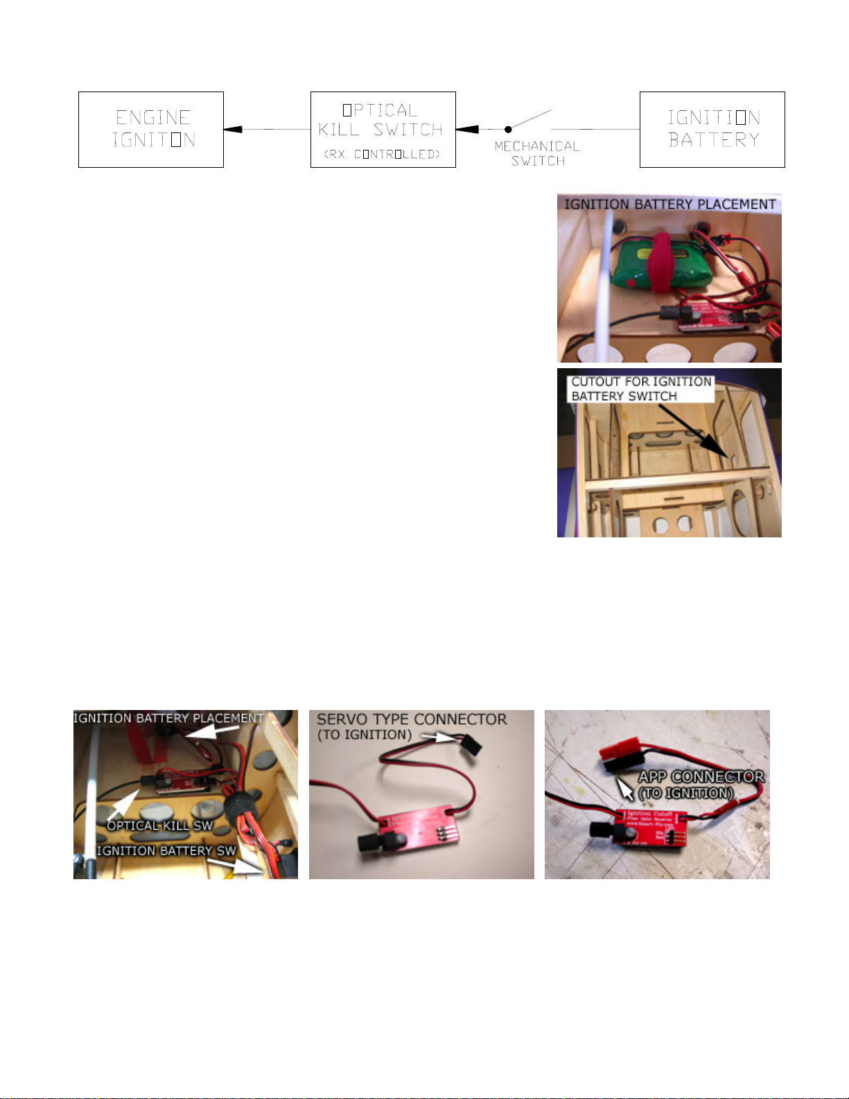
Optical Kill Switch, Ignition 1 SmartFly SFIC
NiMH 6V/1650mA (Ignition) 1 Cermark NIMH6V1650
Ignition DSC HD On/Off Switches, Ignition
(Specify JR or Futaba type) 1 Cermark DSC Switch
DSC HD On/Off Switches, RX
(Specify JR or Futaba type) 1 Cermark DSC Switch
RX NiMH 6V/1650mA (Ignition) 1 Cermark NIMH6V1650