AirWild Hobbies Extra 330L User manual


Doc. No.# AW70-105-01, Copy Right 2005, AirWild Hobbies, Inc. page 2of 2
Contact Us
AirWild Hobbies
23172 Alcalde Drive, Unit B
Laguna Hills, CA 92653
U. S. A.
(949)699-1059
WWW.AIRWILDHOBBIES.COM
This product is sold with exclusion of all warranty expressed or implied, statutory or
otherwise. Buyer assumes all risks of use.
I
In
nt
te
en
nd
de
ed
d
U
Us
se
e
The Extra 330L kit is precisely crafted to produce an airplane that is capable of winning at the highest levels of
precision aerobatic competition. It should only be flown only by radio control pilots experienced with this type of high
performance, low wing airplane at flying sites that comply with the standards set by the Academy of Model
Aeronautics or other nationally recognized radio control sanctioned organizations.
W
Wa
ar
rr
ra
an
nt
ty
y
AirWild will repair or replace individual parts, or all, of the kit for defects in material and / or manufacturing for a
period of thirty (30) days or until the customer builds the kit whichever occurs first.
N
NO
O
E
Ex
xc
ce
ep
pt
ti
io
on
ns
s.
.
A
Ab
bo
ou
ut
t
T
Th
hi
is
s
A
As
ss
se
em
mb
bl
ly
y
M
Ma
an
nu
ua
al
l
This manual divides the assembly into several sub-assemblies; fuselage, stabilizer, wing, fin, landing gear, etc.
Please read each section carefully and familiarize yourself with each step before starting on the particular sub-
assembly. Photos and illustrations are provided in this manual to clarify and detail many sub-assembly steps. The
two should be used together to facilitate your assembly.
S
Sp
pe
ec
ci
if
fi
ic
ca
at
ti
io
on
ns
s
Wing Span: 105 in. (2667 mm)
Fuse Length: 96 in. (2438 mm)
Wing Area: 2048 sq. in. (1.33 sq. m.)

Doc. No.# AW70-105-01, Copy Right 2005, AirWild Hobbies, Inc. page 3of 3
K
K
i
i
t
t
P
P
a
a
c
c
k
k
i
i
n
n
g
g
L
L
i
i
s
s
t
t
This list is provided for your convenience. Before starting on putting the airplane together, go through your kit and
verify that all parts are present and in good condition. Contact AirWild Hobbies at (949)699-1059 for any
discrepancies.
Item No. þDescription Qty.
1rFuselage 1
2rCanopy Hatch 1
3rClear Canopy 1
4rWing Half, Left 1
5rWing Half, Right 1
6rWing Tube, Aluminum, O.D. ∅38 MM x 895 MM 1
7rStabilizer Half, Left 1
8rStabilizer Half, Right 1
9rStabilizer Tube, Aluminum, O.D. ∅16 MM x 40 MM 1
10 rElevator Half, Left 1
11 rElevator Half, Right 1
12 rRudder 1
13 rAluminum Landing Gear 1
14 rFiberglass Cowl 1
15 rFiberglass Wheel Pants 2
16 rFiberglass Landing Gear Fairing 2
17 rSocket Head Cap Screw, Stainless Steel, M3x12, Canopy 8
18 rSocket Head Cap Screw, Stainless Steel, M3x12, Cowl 4
19 rSocket Head Cap Screw, Stainless Steel, M4x16, Main Landing Gear 4
20 rSocket Head Cap Screw, Stainless Steel, M4x16, Wing 2
21 rHinge Rod, Stainless Steel, &2.5MM x 550 MM (rudder use) 1
22 rHinge Rod, Stainless Steel, &2.5MM x 550 MM (elevator use) 2
23 rElevator Hinge Plates 8
24 rRudder Hinge Plates 5
25 rAssembly Manual 1
26 rAirWild Logo Decal 2
A
Ad
dd
di
it
ti
io
on
na
al
l
M
Ma
at
te
er
ri
ia
al
ls
s
Y
Yo
ou
u
M
Ma
ay
y
N
Ne
ee
ed
d
þDescription Qty
Landing Gear Group
rWheel Axles, ∅5/32’’ x 2’’ 2
rWheel Collars, ∅5/32’‘ 4
rSocket Head Cap Screws, #6-32x1’‘ 2
rBlind Nut, #6 2
rMain Wheels, ∅4’‘ 2
Tail Wheel Assembly
rTail Wheel Assembly w/ ∅1-3/4’‘ Wheel 1
Rudder Control
rRudder Control Horn (recommend 5’‘ span) 1
rPull-Pull Cable & Attachment Assembly 1

Doc. No.# AW70-105-01, Copy Right 2005, AirWild Hobbies, Inc. page 4of 4
r
R
udder Bell Crank Assembly (recommend 5’‘ span)
1
rRudder Servo(s) (recommend minimum of 220 oz. in. total) 1~2
Elevator Control
rElevator Control Horn Set 2
rElevator Push Rod (recommend Hanger 9 Pro-Link 2.5’‘) 2
rServo Arm (recommend AirWild MLP Aluminum Servo Arm, 1.25’‘) 2
rServo (recommend 150 oz. in. torque output minimum) 2
rServo Extension Cables (36’‘ ~ 486’‘ configuration dependent) 2
Aileron Control
rAileron Control Horn Set 4
rAileron Push Rod (recommend Hanger 9 Pro-Link 2.5’‘) 4
rServo Arm (recommend AirWild MLP Aluminum Servo Arm, 1.25’‘) 4
rServo (recommend 120 oz. in. torque output minimum) 4
rServo Extension, 12’‘, 22 Awg. 2
rServo Extension, 10’‘ Y-Connect, 22 Awg. 2
Throttle Control
rServo (recommend mini servo) 1
rThrottle Push Rod (recommend Sullivan Carbon Fiber Push Rod Kit) 1
Miscellaneous
rGasoline Engine, 100 cc. 1
rBattery, Ignition, 4.8V/1500mA minimum 1
rHeavy Duty Power On-Off Switch, Ignition Use 1
rOptical Ignition Kill Switch 1
rFuel Tank, 32 oz. 1
rFuel Line, Large, 2’~3’ 1
rFuel Line T 1
rFuel Dot 1
rFuel Vent 1
rReceiver, 7-Channel PCM minimum 1
rBattery, Receiver, 6.0V/2700mA minimum 1
rHeavy Duty Power On-Off Switch, Receiver Use 1
Disclaimer:
This list is provided only as a reference. AirWild Hobbies, Inc. does not in any fashion guarantee nor assumes product liabilities
of their uses by customers. Please consult your local hobby shops or contact manufacturers directly for specific information.
Buyer assumes all risks of use.
F Some General Guidelines To Follow When Working With A Composite Airplane
1. There may be some small loose fragments of harden epoxy resin or balsa shreds caught inside the structure of some
components. Most of the time you can free them loose from cut-outs or slot opening. However should you find unable to shake
loose the last few remaining bits, we often find squirting some thin CA into the structure where the loose pieces are could
conveniently glue them in place.
2. When cutting into the composite skin, always do a round corner instead of a sharp transition. This will reduce chances of cracks
developing from the corner.

Doc. No.# AW70-105-01, Copy Right 2005, AirWild Hobbies, Inc. page 5of 5
For your shopping convenience we have also put together a very complete hardware package that consists of high
-
quality, name-brand products. Package A & B are available. The major difference between them is in the type of
control horns used (legacy Rocket City Super Horn vs. AirWild EFP control horn). To purchase please contact
AirWild Hobbies directly.
AirWild 33% Extra 330L Hardware Package Options
Functional
Group Description
Manufacturer
Part Number
Package A
Qty.
Package B
Qty. Supplier
Landing
Gear Wheel Axles, 3/16''x2'" (2/Pk)
DUB249 1
1
DuBro
Wheel Collars, 3/16" (4/Pk) DUB141 11DuBro
SHCS, 6-32x1" (4/Pk) DUB31511DuBro
Blind Nut, #6 (4/Pk) DUB136 11DuBro
SkyLite Main Wheel, 4" SUL881 22Sullivan
Tail Wheel
Carbon Fiber Tail Wheel Assembly GT302 11Graph Tech
Rudder EFP 5” Rudder Horn AW61-100-01 1N/A AirWild
EFP 5" Bell Crank Asembly AW60-085-01 11AirWild
Rocket City Super Horn, 8-32 (2/Pk) RCL70 N/A 1Nelson
Cable Attach Fitting (4/Pk) AW60-090-01 11AirWild
Pull-Pull Cable, 60 lbs. 60WNA 11AirWild
4-40 Safety Lock Kwik-Link (2/Pk) DUB817 2N/A DuBro
Elevators
EFP Control Horn AW61-112-01 12 N/A AirWild
Rocket City Super Horn, 8-32 (2/Pk) RCL70 N/A 1Nelson
MLP Aluminum Servo Arms, Half, 1.25" Specify Servo 22AirWild
Ball Link, 1/4 HD Ball (2/Pk) DUB899 21DuBro
Titanium Pro-Link, 2.5" (2/Pk) HAN3552 11Hanger 9
Ailerons
Titanium Pro-Link, 2.5" (2/Pk) HAN3552 22Hanger 9
Rocket City Super Horn, 8-32 (2/Pk) RCL70 N/A 2Nelson
MLP Aluminum Servo Arms, Half, 1.25" Specify Servo 44AirWild
EFP Control Horn AW61-112-01 8N/A AirWild
Ball Link, 1/4 HD Ball (2/Pk) DUB899 42AirWild
Fueling Fuel Tank, 32 oz. DUB690 11Du-Bro
Fuel Tubing AER1073 11Aerotrend
Fuel Filler w/ T Coupler HAN115 11Hanger 9
Throttle Carbon Fiber Push Rod, Semi Flex, 36” SUL584 11Sullivan

Doc. No.# AW70-105-01, Copy Right 2005, AirWild Hobbies, Inc. page 6of 6
If you decide to purchase the AirWild h
ardware package, it should leave you with just components are that are
mostly a matter of personal preference to purchase. These may be things such as servo choices, scheme of radio
installation and possibly other appearance related items. Feel free to consult the following list as it reflects what we
used to complete many of our prototype airplanes.
Description Qty.
Comment
AirWild Twist'd Servo Extensions, 36" 2
For elevator servos (use 36” + 12” to build up a 48” length, may vary)
AirWild Twist'd Servo Extensions, 12" 4
For elevator, aileron servos
AirWild Twist'd Servo Y-Connect, 10" 3
For aileron 2X, rudder servos 1X
AirWild Twist'd Servo Extensions, 6" 2
For aileron connections, from Rx
Cermark DSC Switches 3
2 for receiver batteries, 1 for ignition battery
AirWild 35% Pilot Figure 1
Optional
Smart-Fly Optical Kill Switch 1
Ignition Kill (STRONGLY RECOMMENDED FOR SAFETY)
Smart-Fly BatShare 1
Allows you to use two batteries to drive one Rx w/o concern for bat.
Failure
2X battery capacity + redundancy
Cermark NiMH 6V/1650mA 2
For Rx
Cermark NiMH 6V/2700mA 1
For Ignition
CF Nomex Panel, 12"x12" 1
Optional. Used to build floor board for mounting of Rx etc.
AirWild Nova Extra Spinner, 5" 1
Hitec 5945 Hi-Torque Digital Servo 8
Aileron x 4, elevator x 2, rudder x 2
Hitec 5245 Digital Mini Servo 1
Throttle
AirWild MLP Servo Arm, 2.5" 2
For rudder pull-pull use (ganged servos, series configuration)
Hanger 9 Pro Links 4
For rudder pull-pull use (length may vary depending on your placement)
Hanger 9 1/4 HD Double Ball Link 2
For rudder pull-pull use (approximately 2”~2.5” length)
Dubro 1/4 HD Ball Link 2
For rudder pull-pull use (ganged servos, series configuration)
Dynamite Pro Filter 1
Fuel Filter
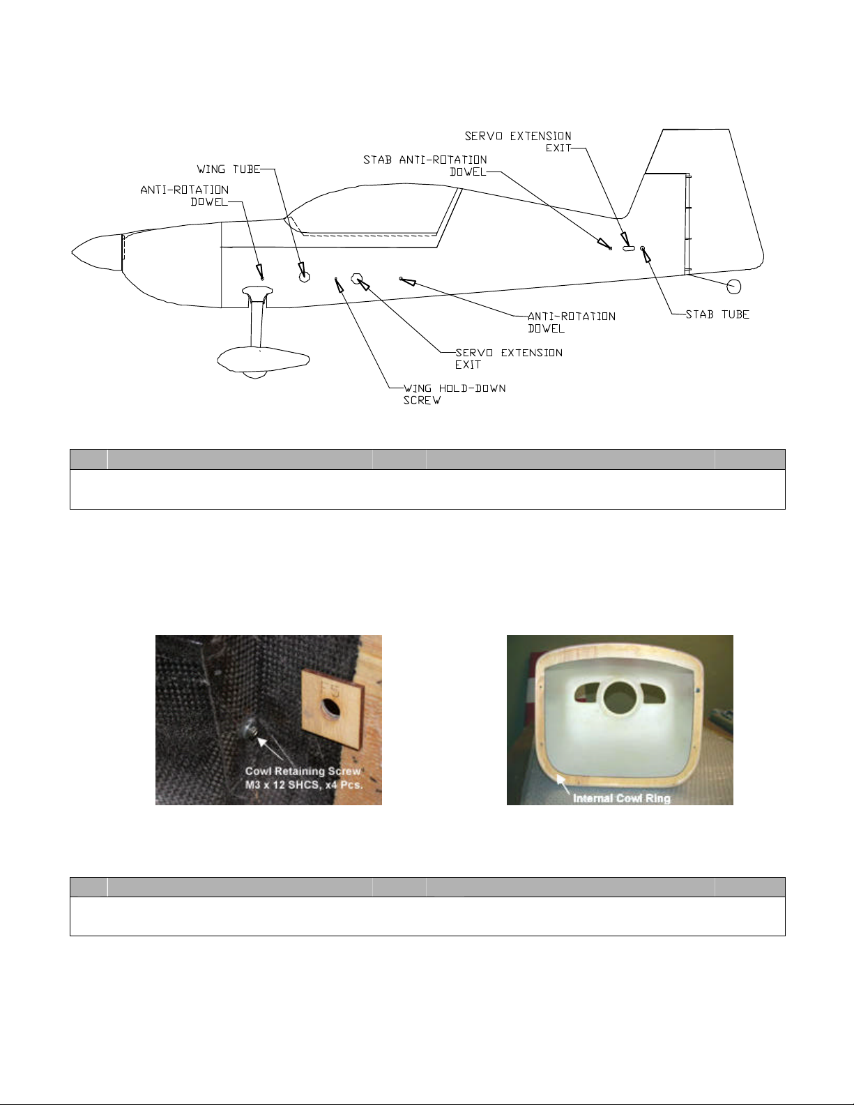
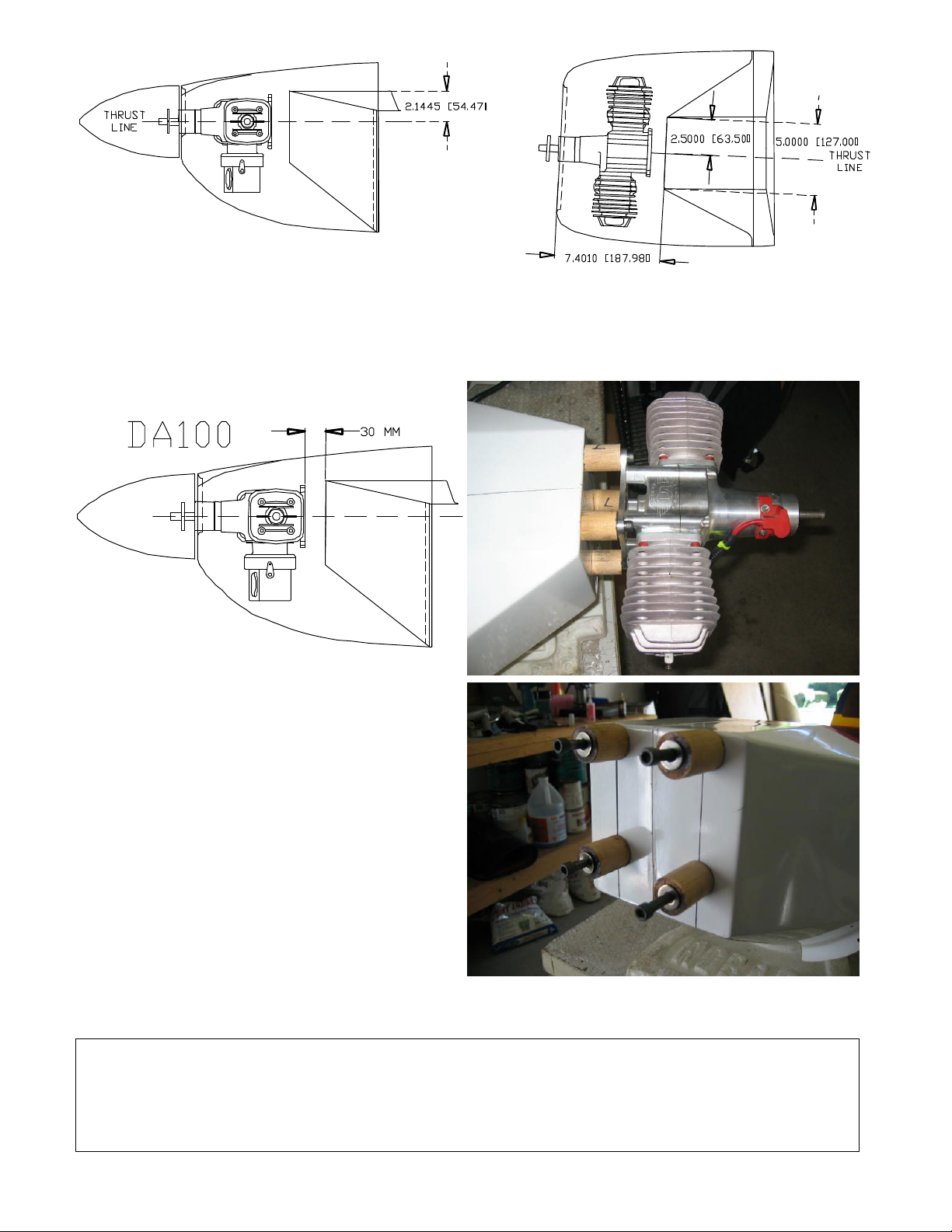
Engine, 100cc, Gasoline1
DA100, 3W106 etc.
Propeller 1
NX 27x10 2-blade, NX 28x10 2-blade, NX 26x12 3-blade (check w/
engine guide)
AirWild WingPAK Pro-Series 1
Optional, for 35% size
Again we want to emphasize that this list reflects our particular requirements only. Make changes in accordance to
your specific considerations.

Doc. No.# AW70-105-01, Copy Right 2005, AirWild Hobbies, Inc. page 7of 7
P
P
r
r
e
e
p
p
a
a
r
r
i
i
n
n
g
g
F
F
u
u
s
s
e
e
l
l
a
a
g
g
e
e
F
F
o
o
r
r
A
A
s
s
s
s
e
e
m
m
b
b
l
l
y
y
Remove fuselage from the shipping box and place it on a flat working surface. Refer to the following illustration to
familiarize yourself with various key features of the fuselage before attempting to assembly the airplane. A good
preparation goes a long way.
S
ST
TE
EP
P
1
1:
:
C
CO
OW
WL
L
A
AT
TT
TA
AC
CH
HM
ME
EN
NT
T
þRequired Parts Qty. þRequired Parts Qty.
rFuselage 1rCowl 1
rSocket Head Cap Screw, M3 x 12 4rWash, M3 (optional) 4
An integrated cowl ring is built into the cowl to facilitate mounting of cowl. Cowl is secured to the fuselage through
the use of four (4) M3 x 12 socket head cap screws.
Screws are attached from the inside of the fuselage as illustrated in the photos below (for illustration only, not actual
Extra 330L). Use of a ball-tip hex key would be most convenient to access the socket head screw at an angle.
S
ST
TE
EP
P
2
2:
:
E
EN
NG
GI
IN
NE
E
M
MO
OU
UN
NT
TI
IN
NG
G
þRequired Parts Qty. þRequired Parts Qty.
rFuselage 1rCowl 1
rSpinner, 5 in. (optional) 1rEngine of Choice (optional) 1
Since there are many excellent choices of engines for this airplane, we did our best to design the engine box to
accommodate various types of engines available. Use the following dimensional drawings in conjunction with your
engine’s outline specifications to determine the correct length of spacers needed to set up your particular engine.
Please carefully consider this issue before proceeding.

Doc. No.# AW70-105-01, Copy Right 2005, AirWild Hobbies, Inc. page 8of 8
Use the reference lines noted above to identify the offset center mark for your engine mount. Mark the bolt pattern
for your particular engine based on the center reference. Please note that there is approximately 2.5-degrees of
right thrust offset built into the engine box design. For illustrational purpose we have provided an installation diagram
for mounting a DA100 twin-cylinder engine which we used for prototyping. Make appropriate changes to the length
of the stand-off for your choice of engine.
Obviously there are various ways to construct engine
spacers. However we find the following method to very
simple and effective. Don’t mind giving them a try:
Stand-off Fabrication: Obtain 0.75’‘ ~ 1’‘ diameter
wooden dowel from your local hardware or lumber
store (ie. Home Depot). Cut dowel to the desired
length. Make sure they are all of even length. Use a
drill press to do the next step. Drill a center hole of the
appropriate diameter for the engine mounting bolt
through the dowel. Next, saturate the through hole and
two ends of the dowel with thin CA. This will prevent
the dowel from splitting under pressure. Repeat same
steps to fabricate three more and you’re done.
Different brand and size of prop may require you to adjust right thrust accordingly. For our prototype setup
(DA100, NX 28x10) we added some minute amount of additional right thrust by shortening the right stand-offs.
Left Stand-off Set: 30 mm long
Right Stand-off Set: 29 mm long

Doc. No.# AW70-105-01, Copy Right 2005, AirWild Hobbies, Inc. page 9of 9
S
S
T
T
E
E
P
P
3
3
:
:
M
M
A
A
I
I
N
N
L
L
A
A
N
N
D
D
I
I
N
N
G
G
G
G
E
E
A
A
R
R
&
&
F
F
A
A
I
I
R
R
I
I
N
N
G
G
þRequired Parts Qty. þRequired Parts Qty.
rFuselage 1rAluminum Landing Gear 1
rSocket Head Cap Screw, M4x16 4rLock Washer, M4 (optional) 4
rGear Fairing 2rAdhesive-Back Velcro (optional)
Place the fuselage up side down and locate the main landing
gear block. Note that four blind nuts for securing the main
landing gear have been pre-installed. Remove the main landing
gear from the shipping box and you will notice that it also has a
matching hole pattern. Simply secure the main landing gear to
the landing gear block using four (4) M4 x 16 socket head cap
screws and washers. To protect the composite surface from the
harsh wear of landing impacts, we actually added a piece of thin
fuel-proof foam sheet underneath the landing gear. In this case
we use a sheet of automotive gasket for this purpose.
Next you are going to add the gear fairing. Your kit comes with
one set (left & right) of gear fairing. The bottom of fairing has a slit. You can pull open bottom of fairing at the slit to
install without having to remove the attached landing gear. Get some adhesive backed Velcro for this installation;
1. Cut a piece of Velcro just long enough to adhere to the inner ball of the fairing. This can be either the hook or
loop part of the Velcro. Whichever you choose to use you will need the mating part for later.
2. Spread open fairing at the slit and mount it to the installed landing gear. Mark on landing gear the end of
fairing (where Velcro tape is).
3. Cut two pieces of mating Velcro and tape them to top and bottom portions of the landing gear at the marking.
4. Tape up slit with a piece of clear 3M tape. This will prevent fairing from flapping in flight.
5. Reinstall fairing. Now it is held to the landing gear by the Velcro tape.
6. If you do not expect to remove landing gear frequently, add a thin bead of silicon caulking between top of
fairing and fuselage to cushion the parts and hold them together more securely.

Doc. No.# AW70-104-01, Copy Right 2004, AirWild Hobbies, Inc. page 10 of 10
S
ST
TE
EP
P
4
4:
:
T
TA
AI
IL
L
W
WH
HE
EE
EL
L
A
AS
SS
SE
EM
MB
BL
LY
Y
Install the carbon fiber tail wheel assembly of choice. We recommend
GraphTech #302. There is hard wood block behind the bottom tail section
to accept self-tapping screws. Locate the seam line which is the center
line and secure the tail wheel bracket down securely.
.
S
ST
TE
EP
P
5
5:
:
C
CL
LE
EA
AR
R
C
CA
AN
NO
OP
PY
Y
&
&
H
HA
AT
TC
CH
H
þRequired Parts Qty. þRequired Parts Qty.
rClear Canopy 1rCanopy Hatch 1
Clear canopy has been pre-trimmed to size. Simply position the canopy
over the hatch and align it to the recessed layout. Once you are satisfied
with the position, glue it to the hatch cover with adhesive such as RC56,
Zap-A-Gap-A-Goo or Liquid Nail. These types of adhesive give you
ample time to work with positioning the canopy, yet once hardened any
excess can be easily trimmed off with a sharp blade.
S
ST
TE
EP
P
6
6:
:
A
AT
TT
TA
AC
CH
HI
IN
NG
G
W
WH
HE
EE
EL
L
P
PA
AN
NT
TS
S
þRequired Parts Qty. þRequired Parts Qty.
rAluminum Landing Gear 1rWheel Axles, ∅5/32’‘ x 2’‘ (optional) 2
rWheel Collars, ∅5/32’‘ (optional) 4rWasher, #6 (optional) 2
rBlind Nut, #6-32 (optional) 2rSocket Head Cap Screws, #6-32x1’‘ 2
rMain Wheels, ∅4’‘ (optional) 2(optional)
Trial fit a main wheel with a wheel pant. Enlarge the wheel cutout if necessary to assure an unrestricted rotation.
Install axles onto the landing gear. Position wheel pants onto landing gear. Adjust them to the correct seating angle
and mark on wheel pants position for the wheel pant hold-down screws.
Remove wheel pants and drill a pilot hole at the mark. Enlarge the pilot hole for mounting a 6-32 blind nut into the
plywood piece that’s on the inside surface of the wheel pant. Use thin CA to secure it in place.
For final assembly, mount the wheel pant with ∅5/32’‘ wheel collars and ∅4’‘ wheel. Secure the wheel pant to
landing gear with a #6-32x1’‘ socket head screw into the blind nut. To obtain a flush mount you may want to install
a piece of spacer between the landing gear and wheel pants.

Doc. No.# AW70-104-01, Copy Right 2004, AirWild Hobbies, Inc. page 11 of 11
S
ST
TE
EP
P
7
7:
:
M
MO
OU
UN
NT
TI
IN
NG
G
F
FU
UE
EL
L
T
TA
AN
NK
K
þRequired Parts Qty. þRequired Parts Qty.
rFuselage 1rFuel Tank (32 oz.) (optional) 1
The best location
for mounting fuel tank is close to the center of gravity of the airplane. As the CG point of the
airplane is about where is wing tube socket is, shown is a 32 oz. Dubro tank resting on the wing tube socket and two
self-installed rails for mounting. Refer to illustration and photos below for more details.

Doc. No.# AW70-104-01, Copy Right 2004, AirWild Hobbies, Inc. page 12 of 12
S
ST
TE
EP
P
8
8:
:
R
RU
UD
DD
DE
ER
R
H
HI
IN
NG
GI
IN
NG
G
þRequired Parts Qty. þRequired Parts Qty.
rFuselage 1rRudder 1
rRudder EFP Hinge Plates 4rStainless Steel Rod, &2.5x550 MM 1
This is about the most tedious part of the entire installation process. Please first read the instructions
completely. Make sure you understand every step before proceeding.
Identify Hinge Plate Locations:
Hold rudder to the fuse as illustrated in the diagram on the right. As noted
do use a piece of 1/8” thick material, such as balsa, to shim the rudder to
the top of the vertical fin. Use the (center of) pre-cut slots on the leading
edge of the rudder as the reference and transfer these locations to the
trailing edge of the vertical fin. These locations will be for the pilot holes.
Cutting Slot for Hinge Plate:
With trailing edge of the vertical fin facing you, drill four (4)
pilot holes in the balsa trailing stock. Then at each hole cut
a horizontal slot just wide enough to snugly accommodate the hinge plate. If you have a Dremel tool,
use it with a router bit to slot. You can also use your Xacto No. 100 blade to cut an initial slot, and
widen it with a hack saw blade. Trial fit each hinge plate to make sure a good fit. DO NOT GLUE
HINGE PLATES AT THIS TIME. However as part of the preparation, do roughen the bonding
surface of the hinge plates by lightly sanding them.
Note: Slots should be centered. Keep the slot size just large enough to fit the hinge plate. Never cut into the
fiberglass skin.
Installing Hinge Plates:
Extra 330L’s removable rudder is secured to the hinge plates with a &2.5MM x 550 MM stainless steel music wire
which is provided in the kit. Please note that the tip of the music wire is rounded to facilitate feeding the wire up
through the embedded balsa blocks in the leading edge of rudder, and also through the hinge plates. Practice a
few times with just the rudder. Slowly feed the music wire up through the wire tunnel from the bottom of the rudder.
Go easy and don’t force your way if encountering any hindrance. The round tip of the wire will gradually home in on
the internal opening. Always keep the music wire straight.
Starting with the bottom hinge plate place it into the matching pre-cut hinge slot in the rudder leading edge and at
the same time feed the music wire up through the wire tunnel and eventually through the hinge plate hole. Continue
this until all four (4) hinge plates are in place and music wire protrudes out of the rudder top. Refer to the following
photos for clarifications.
Feeding Music Wire Through Wire Tunnel –1
(For illustration only, not actual Extra 330L rudder)
Feeding Music Wire Through Wire Tunnel –2
(For illustration only, not actual Extra 330L rudder)
Music Wire & Hinge Plates Installed
(For illustration only, not actual Extra 330L rudder)

Doc. No.# AW70-104-01, Copy Right 2004, AirWild Hobbies, Inc. page 13 of 13
Installing Rudder:
Now you are ready to install rudder hinge plates into the vertical fin. This time start from the bottom plate and work
your way up. With one hand holding the entire rudder / hinge plate assembly use the other hand to move the hinge
plate into slot. Repeat until all hinge plates are in place.
Push rudder closely against the trailing stock of vertical fin. Put a piece of 1/8-inch balsa sheet between the rudder
counter-balance and the top of vertical fin to set clearance between the two. Next perform the following critical
alignment check:
1. Align front of the rudder
counter-balance to the
leading edge of vertical fin
by moving rudder toward or
away from fin. Use
masking tape to temporarily secure rudder to fin.
2. View rudder and fin from behind to make sure rudder is
centered to the trailing edge of vertical fin. Make adjustment
if necessary.
3. When satisfied tack glue hinge plates with a drop of thin CA.
A needle nose CA applicator may be helpful in reaching the
hinge plates. Being that hinge plates are only tack glued in place, you can still easily break the bond
and reposition the hinge.
Remove masking tape and balsa shim. Now rotate rudder to the desired deflection and make sure it can move
freely in both directions. We recommend setting the rudder deflection to no more than 55° as its oversized control
surface is extremely effective. If necessary remove rudder and use a scissor to trim off some of the vertical
fin’s trailing edge fiberglass material to obtain additional throw.
When you are satisfied with rudder alignment and deflection then it’s time to make sure all the hinge plates stay in
place securely. Remove hinge wire and rudder. Permanently glue the hinge plates in place with thin CA. Apply thin
Another Look –Music Wire & Hinges Installed
(For illustration only, not actual Extra 330L rudder)
Guide Hinge Plate Into Slot
(For illustration only, not actual Extra 330L rudder)
All Hinge Plates In Slot
(For illustration only, not actual Extra 330L rudder)

Doc. No.# AW70-104-01, Copy Right 2004, AirWild Hobbies, Inc. page 14 of 14
CA liberally. Use gap-filling CA when necessary to fill any gaps. When cured reinstall rudder, hinge rod and check
for smooth movement.
Deflect Rudder To Desired Angle Glue Hinge Plates In Place
Bend Hinge Rod to Length
Securing Hinge :
Allow rod to protrude out of the top of rudder by about 1/8”. Mark the
bottom of the rod where it enters the rudder. Remove hinge rod and
bend rod 90 degrees at the mark for form an elbow. Leave about 3/4”
and cut away the excess. If you expect frequent removal of rudder, then
use a piece of nylon landing gear strap ( ie. Dubro P/N# 238 ) to anchor
the exposed elbow to the rudder bottom as illustrated in the photo. Or
else you can simply use a bead of silicon caulking to secure the rod.
Simple and clean.
S
ST
TE
EP
P
9
9:
:
E
EL
LE
EV
VA
AT
TO
OR
R
H
HI
IN
NG
GI
IN
NG
G
þRequired Parts Qty. þRequired Parts Qty.
rHorizontal Stabilizer2rElevator 2
rElevator EFP Hinge Plates 8rStainless Steel Rod, &2.5 x 440 MM 2
AirWild Extra 330L features a removable elevator setup.
Similar to the full-scale airplane design the elevator is
cupped in place and secured to the hinging mechanism
through a removable rod.
This assembly mirrors the similar steps done for
rudder. Please first read the instructions
completely. Make sure you understand every step before
proceeding.
Let’s start by first lining up elevator to the stab as shown in the illustration
and transfer hinge plate locations to the trailing stock of stabilizer. These
mark the locations to be slotted for elevator hinge plates.
EFP HINGE PLATE STAB TRAILING EDGE
SS ROD
STAB
ELEVATOR
STABILIZER
ELEVATOR
EFP HINGE PLATES

Doc. No.# AW70-104-01, Copy Right 2004, AirWild Hobbies, Inc. page 15 of 15
F Please note that stab tube socket is located 5
MM in front of the stab trailing edge. Do exercise caution
when cutting the hinge slots. Install stab tube before
cutting. The hard backing may alarm you if you are cutting
into stab tube socket and also minimize damage.
Cut a vertical slot just wide enough to snugly accommodate the hinge plate at each pilot hole location. If you have a
Dremel tool, use it with a router bit to slot. You can also use your Xacto No. 100 blade to cut an initial slot, and
widen it with a hack saw blade. Trial fit each hinge plate to make sure a good fit. DO NOT GLUE HINGE PLATES
AT THIS TIME. However as part of the preparation, do roughen the bonding surface of the hinge plates by lightly
sanding them.
Locate four (4) pieces of EFP elevator horns. Starting from the root
of the elevator place each hinge plate into its matching slot in the
elevator leading edge and at the same time feed the hinge rod up
through the wire guide tunnel and eventually through the hinge plate
hole. Continue this until all four (4) hinge plates are in place and
music wire protrudes out of the elevator tip.
Now you are ready to install the elevator hinge plates into the stab
trailing edge. Again, start from the bottom plate and work your way
out. With one hand holding the entire elevator / hinge plate assembly,
use the other hand to push the hinge plate into slot. Repeat until all
hinges are in place.
Butt elevator closely against the stab. Shorten hinge plates if
necessary to clear stab tube socket. Now rotate elevator to the
desired deflection and make sure it can move about freely in both
directions. We recommend setting the elevator deflection to no
more than 60° as its oversized control surface is extremely effective.
If necessary use a scissor and trim off some of the vertical
fin’s trailing edge to obtain additional throw.
It’s time to make sure all the hinge plates will stay in place. Deflect elevator to max. throw to expose all hinge plates.
Use a fine tip CA applicator and tack glue hinge plates for now with thin CA.
With all hinge plates temporarily held in place, pivot elevator to check
for any misalignment. Being that hinge plates are only tack glued in
place, you can still easily break the bond and reposition the hinge.
Take your time with alignment check until you can ‘‘easily’‘ and
‘‘repeated’‘ install and extract the music wire.
Once you are satisfied with the hinge alignment, remove hinge rod
and elevator. Permanently glue the hinge plates in place with thin CA.
Apply thin CA liberally. Use gap-filling CA when necessary to fill any
voids.
Secure hinge rod to the root with a bead of silicon caulking.
5 MM
EFP HINGE PLATE
HINGE LINE

Doc. No.# AW70-104-01, Copy Right 2004, AirWild Hobbies, Inc. page 16 of 16
STEP 10: RUDDER CONTROL HORN
þRequired Parts Qty. þRequired Parts Qty.
rFuselage / Rudder Assembled 1rAirWild EFP Rudder Control Horn (optional) 1
rDu-Bro 4-40 Safety Lock Quick
Link (optional)
2
Cut rudder horn in half as illustrated. Roughen the mid
section with sand paper.
Refer to the illustration below, mark and cut a 38
MM long x 1.5 MM wide through slot. Please cut
only in the area specified. User assumes all
risks if fails to comply. Now trial fit the EFP
rudder horn into the cut slot by insert one half from
each side. Adjust the slot accordingly to ensure a
good and level fit. Make sure horn is in snug
contact with the embedded balsa block as this
forms the bonding surface.
Adjust horn to make sure that rudder horn’s pivotal points are
lined up with the rudder pivotal point (hinge rod). Also make
sure left and right sides of the horn are equally spaced from the
center line (music wire).
When satisfied with horn’s alignment glue rudder horn into position
with thin CA. Saturate the joint with thin CA. Allow balsa mounting
block to soak up plenty of thin CA and forms a strong structural
bond to the EFP horn. Fill remaining gaps with filler and touch up the
area with paint if needed. Now it is ready for your choice of pull-pull
cable setup.
C
Co
on
nf
fi
ig
gu
ur
ri
in
ng
g
P
Pu
ul
ll
l-
-P
Pu
ul
ll
l
R
Ru
ud
dd
de
er
r
S
Se
et
tu
up
p
Extra 330L’s rudder is designed to accept pull-pull linkage setup. There are various choices of servos and
mechanical setups available. For your convenience a bellcrank based setup is provided in the following section for
your reference only. Modify this setup according to your particular requirements. All items identified here are
optional purchases.
Items Required Quantity Items Required Quantity
Servo(s) 2 or 1 1/4 HD Ball Link 2
AirWild MLP Servo Full Arm, 2.5’‘ 21/4 HD Double Ball Link 2
AirWild 5’‘ EFP Bellcrank Assembly, Offset 1Titanium Pro-Link, 2.5’‘ 4

Doc. No.# AW70-104-01, Copy Right 2004, AirWild Hobbies, Inc. page 17 of 17
AirWild Cable Attachment Fitting 4Pull-Pull Cable, 60 lbs. rated 1
Du-Bro Safety Lock Kwik-Link 25’‘ EFP Rudder Horn 1
We also offer prefabricated AirWild MLP
aluminum rudder bellcrank tray in various
configurations. Both straight and offset
versions as well as Futaba 9152 cutout are
available:
AW60-120-01, 5” Straight Bellcrank
AW60-121-01, 5” Offset Bellcrank
AW60-122-01, 5” Straight Bellcrank, 9152
AW60-123-01, 5” Offset Bellcrank, 9152
For more information please visit our website:
www.airwildhobbies.com
Servo Configuration Output Requirements No. of Servo Example
Dual Rudder Servo 153 oz. in. @ 4.8V, Digital
181 oz. in. @ 6.0V, Digital
2Hitec 5945
Single Rudder Servo 250 oz. in. @ 4.8V, Digital
3338 oz. in. @ 6.0V, Digital
1Hitec 5955TG
[Photo for illustration only. Not actual Extra 330L setup.]
[Photo for illustration only. Not actual Extra 330L setup.]

Doc. No.# AW70-104-01, Copy Right 2004, AirWild Hobbies, Inc. page 18 of 18
S
ST
TE
EP
P
1
11
1:
:
A
AI
IL
LE
ER
RO
ON
N
C
CO
ON
NT
TR
RO
OL
L
H
HO
OR
RN
NS
S
þRequired Parts Qty. þRequired Parts Qty.
rWing Half, Left and Right 1rAileron Servos (optional) 4
rServo Arm, 1.25’‘, Half, Alu. (optional) 4rAileron Control Horn (optional) 4
rHanger 9 Pro-Link, 2.5’‘ (optional) 4r1/4 HD Ball Links (optional) 8
The main wing is 100% pre-fabricated and ready for installation of servos and control hardware. Wing incidence is
factory set @ 0 degree with respect to the thrust line. No additional adjustment is needed. Each wing panel is
secured in place from inside the fuselage with a M4x16 stainless steel socket head cap screw. Refer to the earlier
fuselage illustration to locate the mounting holes.
The only decision you will have to make to complete the wing
assembly is in choosing the type of control horn to use. We
recommend using either AirWild’s very own EFP control horns or the
#8-32 size Rocket City Super Horns (P/N# ROC01B). Information is
provided in the following section for either installation.
Before you start working on installing control horns, there is some
prep works that must be done. First mount your servo into the pre-
cut slot and draw a parallel line 1.25’‘ to the right of the servo center
point. This is the push rod line representing the respective neutral
position when the servo is in neutral. Repeat the same steps for the
other aileron servos. Now we are ready to proceed with mounting
control horns.
A
Ai
ir
rW
Wi
il
ld
d
E
EF
FP
P
C
Co
on
nt
tr
ro
ol
l
H
Ho
or
rn
ns
s
I
In
ns
st
ta
al
ll
la
at
ti
io
on
n
DO NOT cut into the aileron leading edge (balsa spar) as this may cause premature structural failure to the
aileron. All cutting must comply precisely to the illustrations. User assumes all risks for non-compliance.
Let’s work on the left servo first. Refer to illustrations often as we proceed. A piece of hard balsa block is embedded
in the aileron as hard point for control horns. We will now locate the position for cutting two 16 MM long slots for
installing the EFP horns.
1. From the center line you just drew, mark two short
parallel lines 3 MM to the left and to the right.
2. From the leading edge of the aileron draw a parallel
line 16 MM below the leading edge.
1.25"
NEUTRAL LINE
BALSA BLOCK
3 MM
AILERON
LEADING EDGE
AILERON
TRAILING EDGE

Doc. No.# AW70-104-01, Copy Right 2004, AirWild Hobbies, Inc. page 19 of 19
3. Use a Dremel tool or a No. 100 Xacto blade, cut two 16 MM slots as shown. Widen the slots (approx. 1.5 MM)
just enough to allow a snug fit for the EFP horns. Set depth of the horn according to the illustration below.
Once you are satisfied with the placement of the horn, use thin CA to glue it into the balsa block. Be sure to
roughen the bonding surface of the EFP horn with sand paper before gluing. Apply thin CA liberally to soak
the balsa block. Use gap-filling CA to fill any voids as needed. Once cured, repeat the same steps for the rest
of aileron servos.
Note: Due to nature of design this particular control horn setup will result in throw differential as the
hinging surface is offset to the top wing surface. Use your transmitter’s ATV function to make appropriate
compensation.
Slots for EFP Horns
[For illustration only. Not actual Extra 330L]
EFP Horns Glued In Place
[For illustration only. Not actual Extra 330L]
Ball Link Attached
[For illustration only. Not actual Extra 330L]
R
Ro
oc
ck
ke
et
t
C
Ci
it
ty
y
S
Su
up
pe
er
r
H
Ho
or
rn
ns
s
I
In
ns
st
ta
al
ll
la
at
ti
io
on
n
DO NOT cut into the aileron leading edge (balsa spar) as this may cause premature structural failure to the
aileron. All cutting must comply precisely to the illustrations. User assumes all risks for non-compliance.
Being that we have two servos per wing half and
a total of four (4) control horns to install, we will
take you through step by step for one control horn.
You will simply repeat the same steps for the
remaining three (3) horns.
1. In the beginning of this section we had
marked a neutral lines for push rod. Draw
AILERON
LEADING EDGE
16 MM
16 MM
1.5 MM
(DRAWING NOT TO SCALE)
AILERON
LEADING EDGE
(DRAWING NOT TO SCALE)
20 MM
DRILL AND TAP
FOR #8-32 SCREW

Doc. No.# AW70-104-01, Copy Right 2004, AirWild Hobbies, Inc. page 20 of 20
an intersecting line parallel to the leading edge of aileron and 20 MM below. The cross-hair marks the drilling
point for the #8-32 screw. Drill and tap #8-32 thread. Start with a small pilot hole first. This will give you a
clean finish. When drilling make sure aileron is rest against a piece of scrap wood so to prevent delaminating
the composite skin from the balsa hard point block.
2. Once you are satisfied with the initial tap, harden the thread and hole with thin CA. When cured, re-tap once
more to clean up the thread and the harden balsa.
3. Install the remaining Super Horn components to complete
installation. Repeat above steps for the other horns.
Note: Due to nature of design this particular control horn
setup will result in throw differential. Use your transmitter’s
ATV function to make appropriate compensation.
C
Co
on
nn
ne
ec
ct
ti
in
ng
g
A
Ai
il
le
er
ro
on
n
P
Pu
us
sh
h
R
Ro
od
ds
s
There are various schemes available for push rod
setup. This photo illustrates our particular
arrangement for our Edge prototype plane. Again this
information is strictly presented for reference only.
nAirWild 1.25’‘ MLP aluminum servo arm
n1/4 HD ball link
n2.5’‘ titanium Pro-Link push rod
C
Co
on
nf
fi
ig
gu
ur
ri
in
ng
g
A
Ai
il
le
er
ro
on
n
S
Se
er
rv
vo
os
s
Being that each aileron calls for two high torque digital servos, please observe the following guidelines in configuring
your servo;
nUse only high quality, high torque digital servos, 120 oz. in. each minimum. Servo programmability is a plus
but not necessary.
nMake sure servos are matched to the exact neutral position and travel end points. Unmatched servos may
cause binding in aileron movement, uneven deflection, excessive current drain and shortening servo life.
Table of contents
Other AirWild Hobbies Toy manuals
Popular Toy manuals by other brands

Fisher-Price
Fisher-Price Power Wheels Tot Rod T5427 Owner's manual with assembly instructions

Italeri
Italeri Sunderland Mk.III manual

Little Tikes
Little Tikes My First Helicopter quick guide

eX-Mars
eX-Mars Cube Quick manual

Kyosho
Kyosho BMW ORACLE USA-76 instruction manual

Mega Bloks
Mega Bloks Barbie 80247 manual

atd models
atd models Stone Workshop ATD010 instruction manual

Hasbro
Hasbro 79057/79037 instructions

Amewi
Amewi AMXFlight L-39 Assembly and operating manual

Aeronaut
Aeronaut Princess instructions

Stevens Aero Model
Stevens Aero Model ToonSCALE FREDe manual

Playskool
Playskool Swing 'n Score Baseball 06195 instruction manual