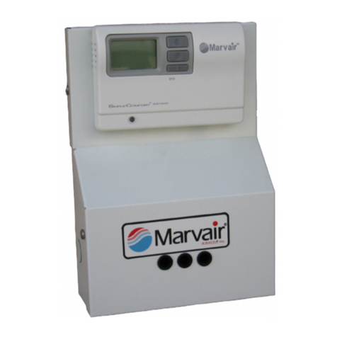
Airxcel Marvair MPC-10 Instruction Manual

1 Marvair MPC-10 PDS/Manual, 09/2020 New
General Description
The Marvair MPC-10 is an HVAC controller designed to control up to ten air
conditioners, that can be either single or dual compressor, for equipment enclosures.
In addition to the control of the air conditioners, the MPC-10 provides alarms
remotely, through BACnet or Modbus, and locally using a built-in Human Machine
Interface (HMI). The controller is factory programmed with standard industry set
points, but can be configured on site or remotely. Settings are retained indefinitely
in the event of a power loss.
➤ Control Up to Ten Air Conditioners in a Shelter
The MPC-10 offers the ability to stage cooling and heating operation for both
dual and single circuit PLC equipped units. This gives the controller a maximum
of 20 stages of cooling for dual circuit units, 10 stages of cooling for single
circuit units, and 10 stages of heating.
➤ Ease of Control and Configuration
The MPC-10 comes standard with a 7-inch color touchscreen HMI which provides
a user-friendly interface. From the main screen of the HMI the user can see room
conditions, HVAC status for each unit, and change cooling/heating set points.
The statuses that can be displayed for each unit are as follows: Cooling, Heating,
Blower, Fault, Standby, Shutdown, and T-Stat Off. If a fault occurs an alarm
window will pop-up that displays a description of the alarm, the time/date at
which it occurred, and the current status of the alarm. Along with the pop-up an
alarm button will appear which allows the user to minimize/maximize the alarm
window. The alarms will be maintained until the fault is fixed and the alarm is
cleared.
The initial setup of the MPC-10 will be done from the built-in HMI. During this
process the user will input the number of units, whether the units are dual or
singe circuit, and the desired communication protocol. Once the initial setup is
complete all other parameters can be changed, at any time, from the 2nd page of
the HMI (F2 Button) or remotely.
Marvair MPC-10 PDS/Manual, 09/2020 New
MANUAL/PRODUCT DATA SHEET
Controller for Up To 10 PLC Based HVAC Systems
Marvair Part # K/40028-100
Features and Benefits
Programmable Logic Board with
Lead/Lag Control
• Balanced Use of Conditioning Equipment
• Sequence the Operation of up to 10 PLC Based Units
• Ensures Maximum Efficiency
• Independent Economizer Control
• Remote Communication (BACnet/Modbus)
Alarms and Lockouts
• High Pressure Lockout (Both Circuits If Applicable)
• Low Pressure Lockout (Both Circuits If Applicable)
• Phase Alarm
• Communication Alarm
• Emergency Shutdown Alarm
• High Shelter Temperature Alarm
• Low Shelter Temperature Alarm

Marvair MPC-10 PDS/Manual, 09/2020 New 2
➤ Remote Communication Protocol
The Marvair MPC-10 comes standard with both BACnet
and Modbus TCP/IP communication protocols and can
be user selected in the initial setup menu. Using these
communication protocols allows the user to access and
change various data points.
Read Only Access
• Room Temperature • High Temperature Alarm
• Room Humidity • Low Temperature Alarm
• Lead Unit • Phase Fault (For Each Unit)
• High Pressure
Refrigeration Circuit A
(For Each Unit)
• Low Pressure Refrigeration
Circuit A
(For Each Unit)
• High Pressure
Refrigeration Circuit B
(For Each Unit)
• Low Pressure Refrigeration
Circuit B
(For Each Unit)
• High Temperature Cut-
Off (For Each Unit)
• Emergency Shutdown
(For Each Unit)
Read/Write Access
• Cooling Set Point • Heating Set Point
• Continuous Blower • Lead Swap
•
Cooling Stage Differential
•
Heating Stage Differential
• Low Temperature Alarm
Set Point
• High Temperature Alarm
Set Point
• Y Fan Purge Time • W Fan Purge Time
• Anti-Short Cycle Time • Lead Swap Period
• Thermostat Offset • AC Unit Shutdown
(For Each Unit)
➤ Thermostat
• Cooling Set Point: 35°F through 95°F
(1.7°C through 35°C) in 1° increments
• Heating Set Point: 35°F through 95°F
(1.7°C through 35°C) in 1° increments
➤ Differential
• Cooling Stage Differential: 1°F through 5°F
(1°C through 3°C) in 1° increments
• Heating Stage Differential: 1°F through 5°F
(1°C through 3°C) in 1° increments
➤ Incoming Power
• 24VDC
➤ Ambient Temperature During Operation
• Minimum: 30ºF (0ºC)
• Maximum: 122ºF (50ºC)
➤ Ease of Installation
The use of Siemens Profinet communication makes
wiring simple. All communication between the HVAC
units and the controller is handled over ethernet cables.
The MPC-10 has eleven ethernet ports located at the
bottom of the controller, one for each unit and one for
remote communication. The order in which the units are
connected does not matter.
➤ Lead/Lag Operation
User selectable changeover from 12 hours to 10 days
in 1-hour increments. If the lead unit loses power, the
next available unit automatically becomes the lead
unit with all the set points of the lead unit. Once a unit
is locked out or losses power it is removed from the
list of available units and will not be called for by the
controller. When the unit is repaired/regains power it
will be added back to the list of available units and can
be called for by the controller. Additionally, a lead swap
button can be found on the HMI allowing service techs
to easily check the operation of each unit.
➤ Alarms
Alarms can be viewed remotely via BACnet/Modbus,
through an on-screen alarm window, and each unit
contains a flash code on the PLC. There are two
classifications of alarms. Unit alarms are specific to the
unit. These alarms will start with the unit designator
followed by the alarm (E.g. Unit 3 Phase Fault). Shelter
alarms apply to the entire building. These alarms include
high/low temperature alarms.
Unit Alarms
• High Pressure Switch A – The refrigerant pressure on
side “A” has exceeded the set point pressure twice in
a cooling cycle. The air conditioner will shut down
and notification will be sent that there is a high-
pressure “A” alarm.
• Low Pressure Switch A – The refrigerant pressure on
side “A” has dropped below the set point pressure
twice in a cooling cycle. The air conditioner will shut
down and notification will be sent that there is a
low-pressure “A” alarm.
• High Pressure Switch B (If Applicable) – The refrigerant
pressure on side “B” has exceeded the set point
pressure twice in a cooling cycle. The air conditioner
will shut down and notification will be sent that
there is a high-pressure “B” alarm.
• Low Pressure Switch B (If Applicable) – The refrigerant
pressure on side “B” has dropped below the set point
pressure twice in a cooling cycle. The air conditioner
will shut down and notification will be sent that
there is a low-pressure “B” alarm.
• Phase – This is activated when the unit is out of
phase. If this alarm is activated the alarm window
on the HMI will pop-up and have a message reading
“Unit X Phase Fault”.
• Emergency Shutdown – This alarm is activated when
the unit is shut down by the user via remote access
or thru the HMI.
• High Temperature Cut-Off (If Applicable) – This is
activated when the heater in the unit exceeds the set
point. Once this occurs the heater will be unavailable
and an alarm will be visible on the HMI.
• Communication – This is activated when a unit loses
communication to the main controller. If this alarm is
activated the alarm window on the HMI will pop-up
and have a message reading “Unit X Communication
Fault”. In the event of this alarm the controller will
not call for the affected unit.
Shelter Alarms
• Low Building Temperature – Activated if the
temperature in the building drops to the selected
temperature. Factory default is 50°F but can be
changed from the parameters page of the HMI in 1°
increments between 30°F and 95°F. If this alarm is
activated the alarm window on the HMI will pop-
up and have a message reading “Low Temperature
Alarm”.
• High Building Temperature – Activated if the
temperature in the building reaches the selected
temperature. Factory default is 90°F but can be
changed from the parameters page of the HMI in 1°
increments between 30°F and 95°F. If this alarm is
activated the alarm window on the HMI will pop-
up and have a message reading “High Temperature
Alarm”.
specifications/features
Marvair MPC-10 PDS/Manual, 06/2020 New 2

3 Marvair MPC-10 PDS/Manual, 09/2020 New
important safety precautions
WARNING
ALWAYS TURN OFF POWER AT THE MAIN POWER SUPPLY BEFORE INSTALLING, CLEANING, OR
REMOVING THERMOSTAT.
• This controller is for 24 VDC applications only; do not use on voltages over 30 VDC
• Do not short across terminals of system control to test operation; this will damage your controller and may void
your warranty
• All wiring must conform to local and national electrical and building codes
• Use this controller only as described in this manual
toinstall mpc-10 telecom controller
WARNING ELECTRICAL SHOCK HAZARD
TURN OFF POWER AT THE MAIN SERVICE PANEL BY REMOVING THE FUSE OR SWITCHING THE
APPROPRIATE CIRCUIT BREAKER TO THE OFF POSITION BEFORE REMOVING THE EXISTING
THERMOSTAT.
IMPORTANT
Marvair MPC-10 installation must conform to local and national building and electrical codes and
ordinances.
Note: Mount the MPC-10 about five feet above the floor. Do not mount the MPC-10, in direct sunlight, behind a door,
or in an area affected by a vent or duct. The MPC-10 is designed for interior use only.
1. Turn off power to the heating and cooling system by removing the fuse or switching off the appropriate circuit
breaker.
2. Put controller against the wall where you plan to mount it (Be sure wires will feed through the wire opening in
the base of the MPC-10).
3. Mark the placement of the mounting holes.
4. Using a drill bit, drill holes in the places you have marked for mounting.
5. Use screws to mount MPC-10 to wall.
6. Feed wires through the bottom left cable gland.
7. Insert stripped, labeled wires in matching wire terminals. See Wiring Diagrams. CAUTION! Be sure exposed portion
of wires do not touch other wires.
8. Gently tug wire to be sure of proper connection. Double check that each wire is connected to the proper terminal.
9. Tighten the cable gland to make a water tight seal.
10.Close the cover on the MPC-10.
11.Plug in ethernet cables from each unit to the bottom of the MPC-10.
12.Turn on power to the system at the main service panel.
13.Test MPC-10 operation as described in “Testing the MPC-10”.
remote sensor installation
1. Remove cover from the remote sensor housing
2. Select an appropriate location for mounting the remote sensor
3. Mount remote sensor unit using hardware provided
4. Install 4 wires between remote sensor and MPC-10 (use shielded cable that is adequately grounded)
a. Wire 1 should run between an unused DC+ terminal in the controller and +V on the temperature/humidity
sensor
b. Wire 2 should run between an unused DC- terminal in the controller and GND on the temperature/humidity
sensor
c. Wire 3 should run between AI0.1 in the controller and RH on the temperature/humidity sensor
d. Wire 4 should run between AI0.0 in the controller and T on the temperature/humidity sensor

Marvair MPC-10 PDS/Manual, 09/2020 New 4
operatinG the mpc-10
There are a total of 8 physical buttons on the HMI, 3 of which are used (shown below). These buttons are reserved to
quickly get to screens that may be used frequently. The following section will go through each screen and explain how to
use them.
HMI Header
1. If the controller is equipped with Modbus communication then this button will be visible. By default, the
controller will be set up for remote communication, however to control the units using the HMI this button
should be pressed. Once pressed the button will then read "Modbus Control: Local" and the user will have
five minutes to make changes to the controller before it is reset to remote communication.
2. The logo can be pressed to take the user to a factory information screen.
3. The alarm indicator will only be visible if there is an unacknowledged fault. Pressing the alarm indicator
will bring up the alarm window were the user will be able to see all of the unacknowledged faults. For
more information see sections on Alarm Window and Alarm Indicators.
4. Here the date is displayed, to change the date simply press the date and enter in the new date on the
on-screen keyboard.
5. Here the time is displayed, to change the time simply press the time and enter in the new time on the
on-screen keyboard.
HMI Physical Buttons
1. The F1 button takes the user to the home screen
2. The F2 button takes the user to the parameter screen
3. The F8 button takes the user to the unit shutdown screen
HMI Main Screen

5 Marvair MPC-10 PDS/Manual, 09/2020 New
1. This button displays the current temperature, humidity, and mode of the controller. The controller can be
in auto (user sets up a range and the controller heats or cools depending on demand), Cooling (Controller
will only cool the space), Heating (Controller will only heat the space), and Off (Controller does not allow
for any cooling/heating). Once the button is pressed the cooling setpoint, heating setpoint, and T-Stat
Mode can be changed.
2. This area displays the status of each unit. The controller can be set up for any number of units between
1 and 10 and will only display the units selected (E.g. If the user selects 5 units then only units 1-5 will
be visible). The status that can be displayed for each unit are as follows: Cooling, Heating, Blower, Fault,
Standby, Shutdown, and T-Stat Off.
HMI Main Screen (with Set Points Shown)
1. Once the button on the main screen is pressed this section appears. From here the user can make changes
to the cooling/heating setpoint in 1° increments or change the mode of the controller. The controller has
a built-in offset of 5° for the cooling and heating setpoints (E.g. If the cooling setpoint is set to 72°F then
the heating setpoint cannot go above 67°F).

Marvair MPC-10 PDS/Manual, 09/2020 New 6
Parameters Screen
1. On this screen the user can change the parameters, within reason, of the controller. Below is a list of
parameters followed by what they control and the range at which it can be adjusted.
a. Cooling Stage Differential - Adjusts the offset at which the controller brings on subsequent stages of
cooling (Range: 1 thru 5)
b. Heating Stage Differential - Adjusts the offset at which the controller brings on subsequent stages of
heating (Range: 1 thru 5)
c. Low Temperature Alarm Set Point - At what temperature the low temperature alarm is triggered
(Range: 35 thru 95)
d. High Temperature Alarm Set Point - At what temperature the high temperature alarm is triggered
(Range: 35 thru 95)
e. Y Fan Purge Time - The length of time(sec.) the indoor blower(s) stay on after a call for cooling is
satisfied (Range: 90 thru 600)
f. W Fan Purge Time - The length of time (sec.) the indoor blower(s) stay on after a call for heating is
satisfied (Range: 90 thru 600)
g. Anti-Short Cycle - The length of time (min.) the compressor is disabled after shutting off (Range: 3
thru 10)
h. Lead Swap Period - The length of time (hrs.) between the controller automatically swapping the lead
unit (Range: 12 thru 240)
i. Thermostat Offset - Offset for the temperature sensor, to correct temperature readings if needed
(Range: -5 thru 5)
2. Continuous blower settings
a. Enable All – Indoor blower runs continuously for all units
b. Enable Lead – Indoor blower runs continuously for lead unit only
c. Disable All – Indoor blower only runs during cooling/heating operation or during purge times set
from the parameters page.
4. Manually change the lead unit. Each press will increment the lead unit once. The change will not take
affect for 5 seconds.

7 Marvair MPC-10 PDS/Manual, 09/2020 New
System Information Screen
1. This button takes the user to the controller setup screen
2. This button takes the user to the main/home screen
Controller Setup Screen
1. Input the number of circuits in the system (single or dual circuit units)
2. Input which communication protocol is required (None, BACnet, or Modbus)
3. Input the number of units the controller will have (Number between 1 and 10)
4. Input to change the company logo shown in the header (Marvair or ICE)
5. This button will return the user to the main/home screen

Marvair MPC-10 PDS/Manual, 09/2020 New 8
Unit Shutdown Screen
To access the screen, press the F8 button on the bottom of the HMI. This screen allows the user to shut down
any of the HVAC units. The status of the unit on the main screen will be displayed as shutdown until the
button is pressed again to resume functionality.
WARNING: When units are shutdown they will be unavailable to aid in heating or cooling the space.
Alarm Window
The alarm window will automatically pop up whenever there is a fault in any of the units tied to this
controller. For each alarm a description will be provided detailing what the alarm is and which unit it is for, a

9 Marvair MPC-10 PDS/Manual, 09/2020 New
time/date that the alarm occurred, and the current status of the alarm. To get rid of the alarm the user must
fix the problem and acknowledge the alarm using the acknowledge button in the bottom right. To hide this
screen the user can press the "X" in the top right-hand corner, to return to this screen press the alarm indicator
shown below in the Alarm Indicator section. The different Status are shown below:
1. I - Incoming, the alarm is currently active
2. O - Outgoing, the alarm occurred at the time specified but was later fixed
3. A - Acknowledged, the alarm has been acknowledged by the user
4. IA - Incoming & Acknowledged, the user has acknowledged the alarm however the alarm is still active
Alarm Indicator
The alarm indicator will appear in the header of the HMI when there is
an unacknowledged alarm. The number at the bottom of the indicator
represents the number of incoming unacknowledged alarms. If the alarm
indicator shows "0" then there is an outgoing alarm that has not been
acknowledged. In this scenario the user would need to acknowledge the
alarm to get rid of the alarm indicator. By pressing the alarm indicator,
you can open or close the alarm window.
testinG the mpc-10
IMPORTANT
Be sure that the crankcase heater (if used) has been energized for at least 24 hours before
starting the unit(s). Double-check all electrical connections before applying power. Air
conditioners with scroll compressors running on 3Ø power must be checked for proper rotation
during the initial start-up. Please refer to the Installation & Operation manual for determining
if the 3Ø compressors are rotating correctly. Incorrect rotation can damage the compressor and
may not be covered by the warranty.
Checking the Cooling Cycle
Procedure:
1. On the parameters page (F2) verify that the cooling stage differential is 1ºF and the anti-short cycle is 3
minutes (default values).
2. Make note of the temperature in the room and then press the thermostat button.
3. Increase the cooling setpoint above the room temperature and decrease the heating setpoint down to
35ºF.
4. Change the thermostat mode to auto.
5. Slowly decrease the cooling setpoint below the room temperature. When the setpoint temperature is 1
degree below the room temperature the first stage cooling will come on. The lead unit will display cooling
as the mode on the home screen. Continue decreasing the cooling setpoint until all stages are on (2
stages per dual circuit unit and 1 stage per single circuit unit).
6. To stop cooling, slowly increase the cooling set point to a temperature higher than the room temperature.
Note: The fan purge allows the indoor fan to run for 90 seconds (by default) after the compressor is off. This
operation provides a small improvement in system rated efficiency.
Checking the Heating Cycle
Procedure: (Applies only to air conditioners with resistance elements)
1. From the main screen, increase the heating set point to a setting higher than room temperature. The fan
will start immediately followed by the electric resistance heater 5 seconds later.
2. To test additional units, continue to increase the heating set point until all units are on, in heating mode.
3. To stop heating, slowly decrease the heating set point to a temperature lower than room temperature.

Marvair MPC-10 PDS/Manual, 09/2020 New 10
mpc-10 Dimensions
20 1
2
"
Front View
15 1
8
"
11
4
"
6"
RH Side View
7
8
"
1"
3
8
" TYP
Rear View
13
8
"
27
8
"
1" TYP
15
8
" TYP
Bottom View

11 Marvair MPC-10 PDS/Manual, 09/2020 New
mpc-10 WirinG DiaGram
P.O. Box 400 •Cordele, GA 31010
156 Seedling Drive •Cordele, GA 31015
Ph: 229-273-3636 •Fax: 229-273-5154
Please consult the Marvair®website at www.marvair.com for the latest product literature. Detailed dimensional data is available upon
request. A complete warranty statement can be found in each product’s Installation/Operation Manual, on our website or by contacting
Marvair at 229-273-3636. As part of the Marvair continuous improvement program, specifications are subject to change without notice.
11 Marvair PMC-10 PDS/Manual, 09/2020 New
Table of contents
Other Airxcel Controllers manuals
Popular Controllers manuals by other brands

DROPSA
DROPSA ADVANCED LUBRICATION CONTROLLER INSTRUCTION AND PRODUCT DATA SHEET

ABB
ABB ACS880-37 Hardware manual

Siemens
Siemens SIMATIC NET SCALANCE WLC711 Getting started

Extron electronics
Extron electronics Basic MediaLink Controllers MLC 52 IR user manual

Maxcess
Maxcess H6630EM user manual

Siemens
Siemens REV13 series instruction manual

nekos
nekos KATO 253 Manual for installation and use

Sebury
Sebury B6 Plus user manual

Zmotion
Zmotion ZMC304X306X Hardware manual

Federal Signal Corporation
Federal Signal Corporation UltraVoice Installation, operation and service manual

Chargery
Chargery BMS16T Series manual

Mitsubishi
Mitsubishi AL2 Series Programming manual