AiSight Aion User manual

User Manual
AiSight Aion

2
Gertraudenstraße 10-12, 10178 Berlin V1.0
Email: info@aisight.de
Phone: +49 (0) 30 40363399 2
Introduction 3
Definitions and Glossary 3
Proper Handling 5
Caution and Warnings 5
Risk Assessment 6
Datasheet 7
Package 9
Sensor Node Description 10
Sensor Orientation 11
Storage Conditions 11
Decommissioning 12
Installation of Aion 12
Mounting 12
Mounting Accessories 13
Powering 15
Connecting 16
Operating 21
Notes and Version Control 23

3
Gertraudenstraße 10-12, 10178 Berlin V1.0
Email: info@aisight.de
Phone: +49 (0) 30 40363399 3
1. Introduction
Aion measures vibration, geomagnetic, and temperature data of your machine. The sensor
picks up the vibration data of your machine which is then going through our machine learning
algorithm. As a result, we can detect anomalies and faults in your machine and prevent
bigger failures. Once a significant fault is detected you will get notified and you will be able
to repair the damage in time without needing to stop the full production.
2. Definitions and Glossary
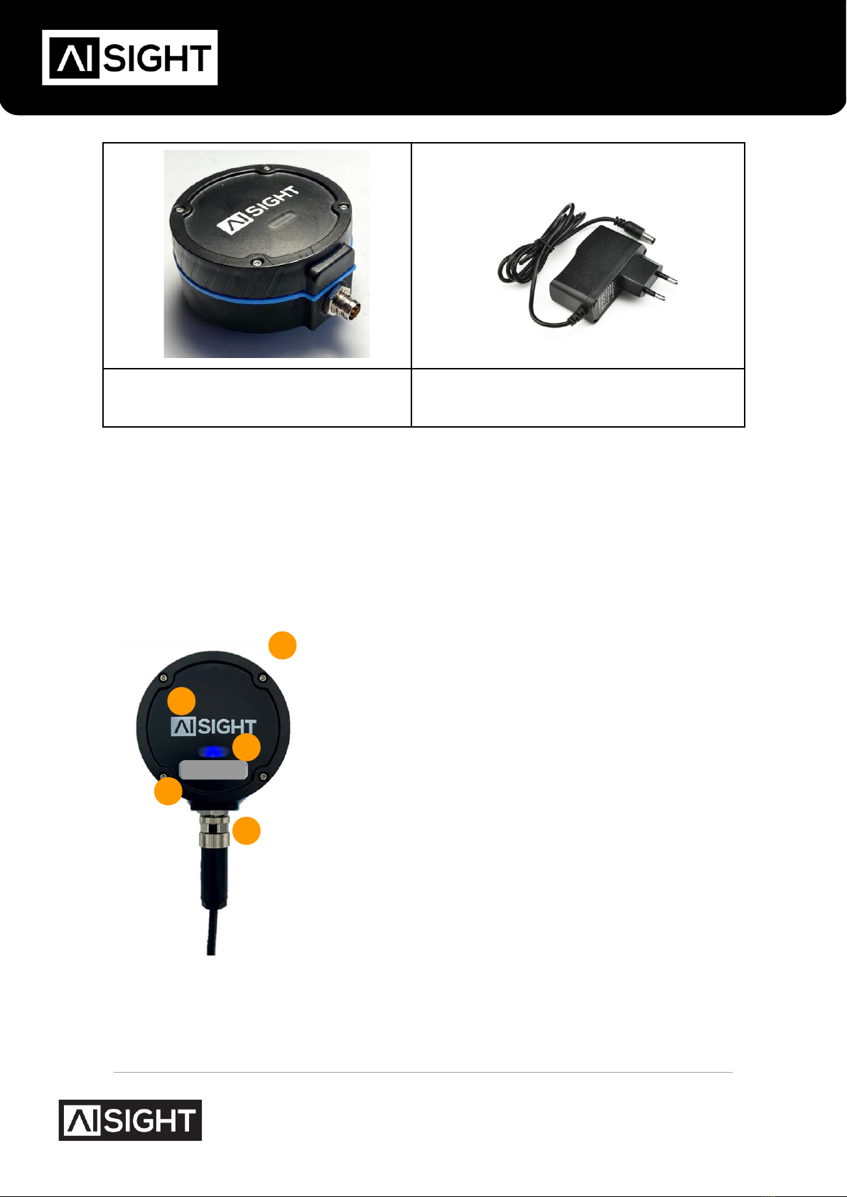
Package: The package received by the client is a recycled paper box that includes the
sensor node, power supply, and mounting interfaces.
Sensor Node: across this document, the words “Sensor Node” will be used to refer to
the AiSight Sensor Node (Aion).
Power Supply: The 90~240VAC to 24V power supply to power up the sensor with
24VDC.
Power Cable: The cable with M8 4 pins connector to power up the sensor directly from
24V from machine panels or other local DC power sources.
MAC Address: Unique identifier number for each sensor node, also known as serial
number.
Mounting Interface: the mounting interface is any mechanical and/or chemical
combination to attach the sensor node to the machine.
Provisioning Application (App): it is a smartphone application that connects with the
sensor node via BLE to input the WiFi credentials.
Bluetooth Low Energy (BLE): is a low power consumption wireless technology
standard used for exchanging data between fixed and mobile devices over short distances
using short-wavelength UHF radio waves.
WiFi Network: is a wireless technology standard used for exchanging data between
fixed and mobile devices over medium-range distances with higher data rates, also
providing access to the internet.
Dashboard: web application used to access the machine status, features, and anomalies.
User: end client of the Aion.
Cloud: where the user’s vibration, geomagnetic, and temperature data will be stored.

4
Gertraudenstraße 10-12, 10178 Berlin V1.0
Email: info@aisight.de
Phone: +49 (0) 30 40363399 4
This manual contains the requirements for the correct installation, provisioning, and
operation of Aion designed for the sole purpose of condition monitoring.
The Aion is designed for, and must only be handled and installed by trained personnel.
Not following this manual may cause malfunction of the sensor node, unprecise anomaly
detection, damage to the machines and to the environment.
Any abnormal behavior or defect on Aion must be informed immediately to AiSight, who
will provide maintenance or replacement of the sensor node.
The user is not authorized to open or to perform any maintenance actions on the sensor
node and power supply.

5
Gertraudenstraße 10-12, 10178 Berlin V1.0
Email: info@aisight.de
Phone: +49 (0) 30 40363399 5
3. Proper Handling
Proper handling of AiSight Aion Sensor Node is critical to prevent any damage.
The following hazard situations should be avoided:
●To drop the item
●Hit the item against sharp or hard surfaces
●Touch the pins of the connector of the Aion connector or its power supply with any
metal tools or conductive devices
●Use excessive force when mounting the unit
●In case of the use of magnet accessory:
●avoid impact (due to magnetic attraction) when mounting the sensor on the
desired surface.
●do not put any operator body parts between the magnet and metal surfaces
●In case of use of swivel mounting, force the mounting without the presence of a
thread
●Expose the item to temperatures above 90°C
●Expose the item to any reactive chemicals
●In the case of using the power cable instead of the power supply, only trained
electricians can handle the installation of the cable
The user’s Environmental, Health, and Safety (EHS) manager has to be consulted to
ensure a safe installation of the sensor. The technicians who are responsible for the
installation must follow all EHS guidelines, use the required Personal Protective Equipment
(PPE) and use the proper and indicated tools.
For adhesive mounting options, the cure time must be respected before the operation of
the machine restarts.
The power supply cable or the power cable alone must be securely tied to fixed parts of
the body of the machine, cable trays, or ducts. It's suggested to use cable ties, clips, and
clamps.
3.1. Caution and Warnings
!

6
Gertraudenstraße 10-12, 10178 Berlin V1.0
Email: info@aisight.de
Phone: +49 (0) 30 40363399 6
Caution indicates a hazard that could cause minor personal injury, or property damage if
ignored.
A warning indicates a hazard that could cause severe personal injury, death,
or substantial property damage if ignored
3.2. Risk Assessment
The risk assessment of the sensor is based on the CENELEC GUIDE 32 and it can be
shared. Please contact AiSight if you need any further information.
!

7
Gertraudenstraße 10-12, 10178 Berlin V1.0
Email: info@aisight.de
Phone: +49 (0) 30 40363399 7
4. Datasheet
Compliance and Safety
Compliant with
CE, FCC
Vibration Measurements
Type
3-axis digital accelerometer
Bandwidth
6kHz
Acceleration Range
Up to ±16g
Resolution/Sensitivity
<0.5 mg/LSB
Noise level
<110 μg/√Hz
Geomagnetic Measurements(2)
Type
3-axis digital geomagnetic sensor
Bandwidth
360Hz
Magnetic range
±1300μT (x,y-axis), ±2500μT (z-axis)
Resolution/Sensitivity
0.3μT
Temperature Measurements
Refresh Rate
104 Hz
Temperature Range
-40 to 105 °C
Sensitivity/Resolution
256 LSB/°C
Environmental
Sensor Node Temperature Range
–20 to 85 °C
Power Supply Temperature Range
-20 to 60 °C
Ingress Protection
IP67
Salt and Mist
Standards IEC 60068-2-11: 2000
Power
Input connector
IEC Type C
Input voltage
90 –264 VAC
Input frequency
47 –63 Hz
Output voltage
24V
Maximum output ripple
<200 mV pk-pk
Output power
>18W

8
Gertraudenstraße 10-12, 10178 Berlin V1.0
Email: info@aisight.de
Phone: +49 (0) 30 40363399 8
Power (continuation)
Interface connector 1
M8, 4 pins
Interface connector 2
BB-02XXMA-QL8MPP
External power supply certifications
CE, UL, TUV, TUV/GS, Energy Efficiency
Level VI; European CoC Tier 2
Emissions and Immunity approvals
EN55022 Class B, EN61000-3-2 Class
A, EN61000-3-3, EN55024, +
additional certifications depending on
the model
Safety approvals
IEC60950-1, EN60950-1, UL60950-1
Connectivity for Provisioning (Bluetooth)
Protocol
Bluetooth v4.2 BR/EDR and BLE
specification
Radio
NZIF receiver with –97 dBm sensitivity,
Class-1, class-2 and class-3
transmitter, AFH
Connectivity for Operation (WiFi)
Protocol
802.11 b/g/n (802.11n up to 150 Mbps)
Frequency range
2412 to 2484 MHz
Integrated antenna
Able to connect to routers/gateways up
to 30 meters.
User Interface
Web Based Dashboard
Custom made client solution
Physical(3)
Dimensions
72mm x 61mm x 26mm
Weight
130g
Mounting Accessories
M5 tapped hole, magnet, motor fins
adaptor, screw pad adaptor, food
contact safe cyanoacrylate or industrial-
grade epoxy
Connectivity
M8-4 connector

9
Gertraudenstraße 10-12, 10178 Berlin V1.0
Email: info@aisight.de
Phone: +49 (0) 30 40363399 9
5. Package
Once receiving the sensor node, the user must verify the conditions of the package itself
and all items inside the package. The package must include always:
●1x Aion (Figure 5.2)
According to customers needs, the package can also include any combination of the
following items:
●1x Cincon Power Supply (TRE25R240-1131G64 VI) (Figure 5.3)
●1x Sensor-Actuator power cable with a female M8 4-pin connector
●1x 10ml general-purpose silicone grease
●1x Motor fin adaptor
●1x Threaded adaptor
●1x SmCo Stainless Steel Magnet
Figure 5.1 - Aion Packaging

10
Gertraudenstraße 10-12, 10178 Berlin V1.0
Email: info@aisight.de
Phone: +49 (0) 30 40363399 10
Figure 5.2 - Aion
Figure 5.3 - Power Supply TRE25R240-
1131G64
The QR code is connected to a web address containing all the most updated information
and guidelines given from AiSight to their customers.
5.1. Sensor Node Description
1) Sensor node
2) AiSight Logo
3) Status LED
a) White: Sensor on
b) Blue: Waiting for provisioning
c) Yellow: Connected to the WiFi-only
d) Green: Connected to the WiFi and Cloud
e) Purple: Updating
f) Red: Problems with the WiFi connection
4) M8 male connector
5) Unique MAC Address (or serial number)
Figure 5.4 - Aion Sensor Description

11
Gertraudenstraße 10-12, 10178 Berlin V1.0
Email: info@aisight.de
Phone: +49 (0) 30 40363399 11
5.2. Sensor Orientation
The Aion is a three axial vibration and geomagnetic sensor. The axes for both
measurements are configured as shown in Figure 5.5. The “x” axis is aligned with the logo,
while the “y” is aligned with the M8 connector. The “z” axis covers the resulting dimension,
perpendicular to the body of the sensor.
Figure 5.5 - Sensor orientation
5.3. Storage Conditions
If the user decides to install the sensor node at a later date it is recommended that the
complete package must be stored in a safe place, away from direct sunlight, with
temperatures between 0° to 35° and relative humidity below 70%.
X
Z
Y

12
Gertraudenstraße 10-12, 10178 Berlin V1.0
Email: info@aisight.de
Phone: +49 (0) 30 40363399 12
5.4. Decommissioning
Even though the sensor node complies with the European Union Waste
Electrical and Electronic Equipment (WEEE) Directive, the user is not
permitted to discard the sensor node, power supply and removable
mounting. At the end or termination of the contract between the user and
AiSight, all the above mentioned items must be shipped back to the address
indicated on the contract.
AiSight is responsible for managing all electronic waste, together with its
partners.
The user is permitted to remove and discard any remaining of adhesive
parts (if included in the mounting options).
6. Installation of Aion
To successfully install Aion and directly read the data on the AiSight dashboard three
steps are needed:
1. Mounting: Mount Aion with the help of the provided mounting accessories
2. Powering: Plugging Aion to power
3. Connecting: Provision the sensor to wifi
4. Operating. Read data from AiSight Dashboard
All the steps to successfully perform the above steps are described in the document
“Service and Installation instructions”.
Please read the following steps to get familiar with the installation.
6.1. Mounting
The first step is to identify the ideal mounting position on the machine. As we are
measuring the vibration of the machine and we rely on very good transmission of the data it
is not recommended to attach the sensor anywhere on the machine.
Ideally, if a probable failure location is known, it is recommended to place the sensor as
close as possible to it. Otherwise, try to identify one of the mounting positions on the motor
such as presented in the Figure 6.1.

13
Gertraudenstraße 10-12, 10178 Berlin V1.0
Email: info@aisight.de
Phone: +49 (0) 30 40363399 13
It is advised to align the X or Y axes of Aion with the shaft of the machine.
Figure 6.1 - Ideal mounting points for rotating machines
6.1.1. Mounting Accessories
The Aion sensor can be equipped with various mounting accessories depending on the
application and the customer’s needs.
Some mounting accessories are listed in Table 6.1.
Accessory
Ideal Application
SmCo Stainless Steel Magnet
The monitored machine has a flat magnetic
surface.
AiSight Screw Pad
The monitored machine does not have a flat
magnetic surface or the threaded hole is in a better
monitoring position.

14
Gertraudenstraße 10-12, 10178 Berlin V1.0
Email: info@aisight.de
Phone: +49 (0) 30 40363399 14
AiSight Motor Fin adaptor
No flat surfaces nor threaded holes are available
closeby to an ideal monitoring position. The adaptor
can be either glued with the Loctite EA 3463 or
Loctite AA330.
AiSight Flat Pad
Non magnetic and non flat surface. The pad can be
either glued with the Loctite EA 3463 or Loctite
AA330.
Table 6.1: Mounting Accessories
In the case the mounting accessory has to be glued, AiSight suggests the cleaning of the
surface with a professional surface cleaner (such as Weicon Surface Cleaner) and a cloth.
Then, sand the surface to improve the gluing process and then clean the surface again from
sanding residuals.
Once the mounting accessory is successfully fixed in the desired position of the machine,
Aion sensor can be coupled to it and the User can go to step n. 2 of powering Aion.
For additional information regarding the mounting installation procedure, please refer to
the document “Service and Installation instructions” and watch the tutorials at the AiSight
Youtube Channel.

15
Gertraudenstraße 10-12, 10178 Berlin V1.0
Email: info@aisight.de
Phone: +49 (0) 30 40363399 15
6.2. Powering
Two options to power up the sensor can be used depending on how the customer prefers
and how the contract between the two parts was agreed:
●The first option is to use the custom AC power supply compatible with the
product, the TRE25R240 with 3m long cable and female M8 4 pin connector,
as shown in Figure 6.3.
Figure 6.2 - AiSight custom power supply with M8 connector
●use a 2-wire or 4-wire cable with M8 4-pin female connector to directly
connect the sensor node from existing machine panels or switchboards that
has DC connection from 8 to 48V (24V recommended). A cable with an
overmolded connector can be used or a cable with a field installable
connector, as shown in Figure 6.3. The pinout is also described below.
Figure 6.3 - Example of a cable with M8 female plug connector
Pin 1 [Brown cable] –VDD (Recommended 24V with 0.125A/3W
consumption)
Pin 2 [White cable] –DO NOT CONNECT
Pin 3 [Blue cable] –Ground connection

16
Gertraudenstraße 10-12, 10178 Berlin V1.0
Email: info@aisight.de
Phone: +49 (0) 30 40363399 16
Pin 4 [Black cable] - DO NOT CONNECT
Only authorized and technically trained personnel should handle and install the
power supplies and cables, specifically when access to panels and switchboards
are necessary.
!

17
Gertraudenstraße 10-12, 10178 Berlin V1.0
Email: info@aisight.de
Phone: +49 (0) 30 40363399 17
7. Connecting
Once Aion has a blue steady LED light, it is ready to be BLE provisioned using the Aisight
App available on the App store.
https://apps.apple.com/de/app/aisight-ble-provisioning/id1531196751
Figure 8.1. Sensor node connected to power and ready to be provisioned
The provisioning can be performed by the following steps:
1. Download and open the AiSight App https://apps.apple.com/de/app/aisight-ble-
provisioning/id1531196751
2. Turn on the Bluetooth on your device
3. Click on “Provision Device”. After a brief time, the Wi-Fi/BLE board will be identified
(Figure 8.2c). Each Aion has a unique device ID that is shown on the Aion sensor
4. Select the ID of the Aion node you want to provision
5. Selection the Wifi network you want to connect Aion to and insert the password
6. Finish. Once the LED turns green Aion is already sending data and monitor the
machine

18
Gertraudenstraße 10-12, 10178 Berlin V1.0
Email: info@aisight.de
Phone: +49 (0) 30 40363399 18

19
Gertraudenstraße 10-12, 10178 Berlin V1.0
Email: info@aisight.de
Phone: +49 (0) 30 40363399 19
(a) (b) (c)
Figure 8.2. (a) Initial screen and (b) list of available sensors and (c) Screen confirming the
connection of the sensor with the Wi-Fi.
By clicking on the OK button, the user can start the provisioning process for the next
sensor node in range. The sensor node should now change its colour to yellow as soon as
connected to the Wi-Fi and shortly after turn green confirming the connectivity with our
platform in the cloud, as shown in Figure 4.15. If the node stays with the yellow LED on, the
network requirements presented at the beginning of this document must be reviewed.
Other manuals for Aion
2
Table of contents
Popular Accessories manuals by other brands

Evenflo
Evenflo Pivot Xpand Stroller Market Basket instructions

Creative
Creative Crossover M Building instructions

System Sensor
System Sensor B200SR Installation and maintenance instructions

Modine Manufacturing
Modine Manufacturing ECO CGD Technical manual

Lucent
Lucent Flexent Modular Cell 4.0B installation manual

Knick
Knick Series SE 707-Memosens Instructions for use