Aiwa TN-106 User manual

TELEPHONE
TN-106
S/M Code No. 09-995-331-2O1
YTH
SERVICE MANUAL
DATA

2
SPECIFICATIONS
•
Design and specifications are subject to change without
notice.
REF. NO PART NO. KANRI DESCRIPTION
NO.
ACCESSORIES/PACKAGE LIST
1 8Z-PW6-902-010 IB,106YTH (C)
1 8Z-PW6-901-010 IB,106YTH (E)
2 88-PCD-627-010 CORD, ST9-2WA
3 87-301-162-410 SW+3.8-32

43
REF. NO PART NO. KANRI DESCRIPTION
NO.
REF. NO PART NO. KANRI DESCRIPTION
NO.
ELECTRICAL MAIN PARTS LIST
• Regarding connectors, they are not stocked as they are not the initial order items.
The connectors are available after they are supplied from connector manufacturers upon the order is received.
IC
87-A21-134-010 IC,W91340N
S4-650-020-000 IC,DBL5002
TRANSISTOR
84-LB2-699-080 TR,2SC945A/P
S8-004-300-000 TR,KSP43
S8-009-200-010 TR,KSP92
S8-090-130-080 TR,KTC9013H
DIODE
87-A40-586-080 DIODE,1N4004
87-A40-246-080 DIODE,IN4148 T-72
S0-102-701-210 ZENER,BZX55-C27
S0-100-361-220 ZENER,BZX55-C3V6
87-A40-587-080 ZENER,BZX55-C5V1
MAIN C.B
C1 87-A11-064-010 CAP,M/P 0.47-250 K MMCF0250K 4
C2 87-010-405-040 CAP,E 10-50
C6 87-010-247-040 CAP,E 100-25
C13 87-010-405-040 CAP,E 10-50
C15 87-010-405-040 CAP,E 10-50
C19 87-010-444-080 CAP,E 22-50
C20 87-015-695-010 CAP,E 1-50
FR1 88-PCD-613-080 RES,FUSE 10-1/2W J NFR25H 230
J1 88-PCD-615-010 JACK,MODULAR 2 P E5562-000111
SCR1 87-A91-039-010 VRIS,SAS-391KD07
SW1 88-PCD-614-010 SW,22L01-OA
SW2 87-A91-036-010 SW,SL 2-2-2 SKA-22D10-G4-NA
SW3 87-A91-037-010 SW,SL 1-1-3 SKA-13D07-G4-NA
X1 87-A70-167-010 VIB,CER 3.58MHZ CSA3.58MG
KEY C.B
REC/MIC C.B
TRANSISTOR ILLUSTRATION
ECB
2SC945 EBC
KSP43
KSP92
KTC9013H

12345678910 11 12 13 14
A
B
C
D
E
F
G
H
I
J
K
65
WIRING
MAIN C.B
(PATRS SIDE)
KEY C.B
(PATTERN SIDE)
REC/MIC C.B
(PATTERN SIDE)
43
21
1
1
14
4
8
5
1
18
10
13
9
ECB
ECB
ECBECB
ECBECB
RINGER
TEL. LINE
HIGH MIDDLE LOWPULSE TONE
BLK
YEL
GRN
RED
BLK
YEL
GRN
RED
MIC1
(MIC) SP2
(SPEAKER)
SP1
(SPEAKER)
1
13
3
6
9
2
5
8
0
1
4
7
STOREMEMOFLASHREDIAL
/PAUSE
BA
NOTE

87
SCHEMATIC DIAGRAM
J1

109
1-4
5
6
7
8
9
10
11
12
13
14
15-18
IC, W91340N
Pin No. Pin Name I/O Description
IC DESCRIPTION
Column-Row Inputs
H/P MUTE
VSS
XT
______
XT
___________
T/P MUTE
HKS
______
DP
DTMF
MODE
VDD
Column-Row Inputs
The keyboard inputs may be used with either a standard 5*4 keyboard or an
inexpensive single contact (Form A) keyboard. Electronic input from a µC can also be
used. A valid key is defined as a single row being connected to a single column.
The H/P MUTE is a conventional inverter output. During pulse dialing, flash break or
hold period, this output is active high; otherwise, it remains in low state.
Power input pins.
A built-in inverter provides oscillation with an inexpensive 3.579545MHz crystal or
ceramic resonator.
A built-in inverter provides oscillation with an inexpensive 3.579545MHz crystal or
ceramic resonator.
___________-
The T/P MUTE is a conventional CMOS N-channel open drain output. The output
transistor is switched on during dialing sequence and flash break time. Otherwise, it is
switched off.
Hook switch input.
________
HKS=VDD: On-hook state. Chip in sleeping mode, no operation.
________
HKS=VSS: Off-hook state. Chip is enabled for normal operation.
________
HKS pin is pulled to VDD by an internal resistor.
N-channel open drain dialing pulse output.
______
Flash key will cause DP to be active in either tone mode or pulse mode. The timing
diagram for pulse mode is shown in Figure 1 (a, b, c).
In pulse mode, this pin remains in low state at all times. In the tone mode, it will
output a dual or single tone. Detailed timing diagram for tone mode is shown in Figure
2 (a, b, c).
Pulling mode pin to VSS places the dialer in tone mode.
Pulling mode pin to VDD places the dialer in pulse mode with M/B ratio of 40:60 (10
ppS, except for W91342N/W91342AN=20 ppS.)
Floating mode pin places the dialer in pulse mode with M/B ratio of 33.3:66.7 (10 ppS,
except for W91342N/W91342AN=20 ppS.)
Power input pins.
The keyboard inputs may be used with either a standard 5*4 keyboard or an
inexpensive single contact (Form A) keyboard. Electronic input from a µC can also be
used. A valid key is defined as a single row being connected to a single column.
I
O
I
I
O
O
I
O
O
I
I
I
Output Frequency
Specified Actual Error %
R1 697 699 +0.28
R2 770 766 -0.52
R3 852 848 -0.47
R4 941 948 +0.74
C1 1209 1216 +0.57
C2 1336 1332 -0.30
C3 1477 1472 -0.34
WAVE FORM
1U1 Pin 1(VCC) VOLT/DIV: 5V
While the receiving bell is ringing TIME/DIV: 1S
2U1 Pin 3(LFTC1) VOLT/DIV: 5V
TIME/DIV: 1S
3U1 Pin 4(LFTC2) VOLT/DIV: 5V
TIME/DIV: 1S
4U1 Pin 6(HFTC1) VOLT/DIV: 5V
TIME/DIV: 1S
5U1 Pin 7(HFTC2) VOLT/DIV: 5V
TIME/DIV: 1S
6U1 Pin 8(O/P) VOLT/DIV: 5V
TIME/DIV: 1S
7U2 Pin 1-4(C1-C4) VOLT/DIV:2V
While the dial button is being pressed TIME/DIV:10mS
8U2 Pin %-*(R1-R4) VOLT/DIV: 2V
TIME/DIV: 10mS

11
9U2 Pin 7(XT) VOLT/DIV: 2V
______
Pin 8(XT) TIME/DIV: 500nS

12
MECHANICAL EXPLODED VIEW 1/1
1
2
3
4
5
7
8
9
10 11
12
13
14 14
5
P.C.B
P.C.B
P.C.B
15
16
6
B
B
A
A
A
C
17
SH,HS

13
REF. NO PART NO. KANRI DESCRIPTION
NO.
REF. NO PART NO. KANRI DESCRIPTION
NO.
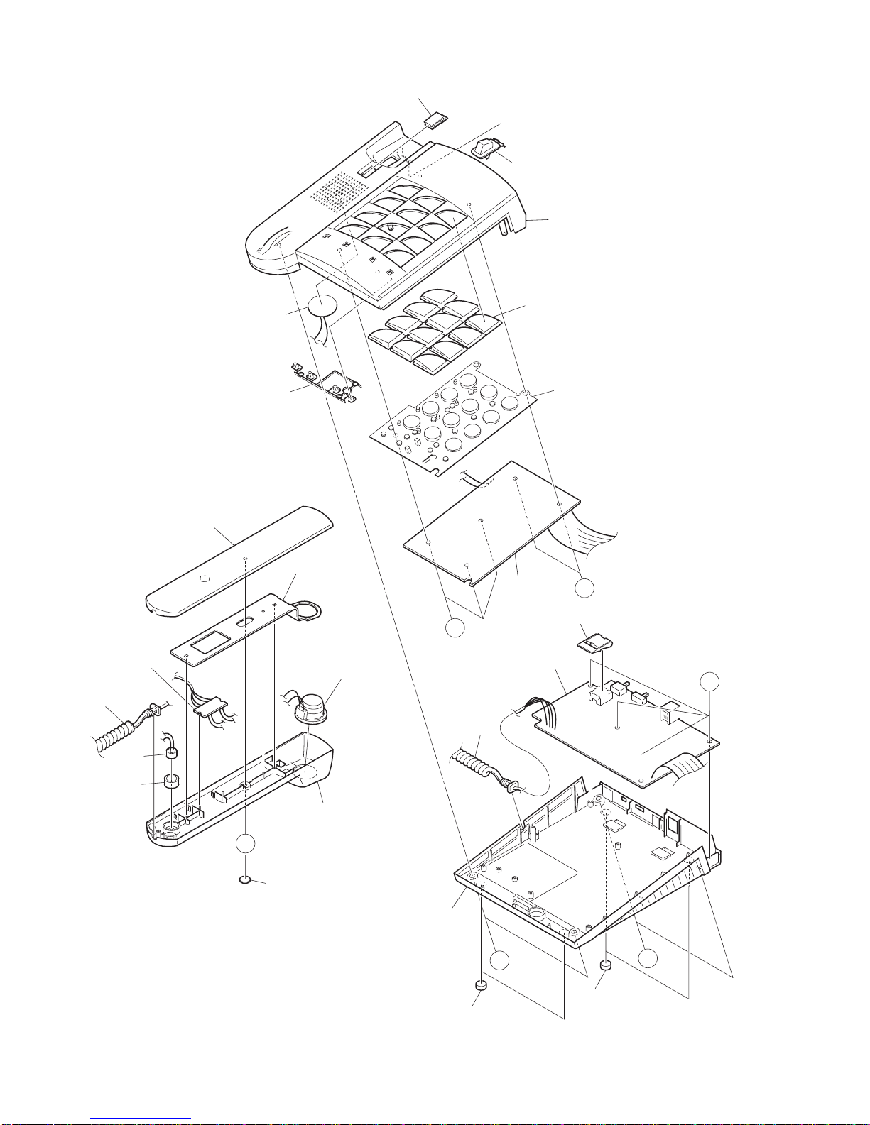
MECHANICAL PARTS LIST 1/1
Basic color symbol Color Basic color symbol Color Basic color symbol Color
B Black C Cream D Orange
G Green H Gray L Blue
LT Transparent Blue N Gold P Pink
R Red S Silver ST Titan Silver
T Brown V Violet W White
WT Transparent White Y Yellow YT Transparent Yellow
LM Metallic Blue LL Light Blue GT Transparent Green
LD Dark Blue DT Transparent Orange
COLOR NAME TABLE
1 8Z-PW6-024-010 CABI,REAR H/S G B/U<YTHG>
1 8Z-PW6-034-010 CABI,REAR H/S L B/U<YTHL>
1 88-PCD-050-010 CABI,REAR H/S WHT B/U<YTHW>
2 88-PCD-206-010 HLDR,SPKR H/S B/U
3 8Z-PW6-023-010 CABI,FR H/S G B/U<YTHG>
3 8Z-PW6-033-010 CABI,FR H/S L B/U<YTHL>
3 88-PCD-049-010 CABI,FR H/S WHT B/U<YTHW>
4 88-PCD-222-010 HLDR,MIC H/S
5 88-PCD-626-010 CORD,STI-4WB
6 88-PCD-608-010 VIB,PIEZO 2.9KHZ LF-35B-29FB
7 88-PCD-046-010 HANGER,H/S WHT B/U<YTHW>
7 8Z-PW6-026-010 HANGER,HOOK G B/U<YTHG>
7 8Z-PW6-036-010 HANGER,HOOK L B/U<YTHL>
8 8Z-PW6-021-010 CABI,TOP G B/U<YTHG>
8 8Z-PW6-031-010 CABI,TOP L B/U<YTHL>
8 8Z-PW6-010-010 CABI,TOP WHT B/U<YTHW>
9 8Z-PW6-007-010 BTN,DIAL B/U
10 8Z-PW6-025-010 BTN,FUNC G B/U<YTHG>
10 8Z-PW6-035-010 BTN,FUNC L B/U<YTHL>
10 8Z-PW6-012-010 BTN,FUNCTION WHT B/U<YTHW>
11 8Z-PW6-201-010 BTN,RUBBER B/U
12 8Z-PW6-027-010 BTN,HOOK G B/U<YTHG>
12 8Z-PW6-037-010 BTN,HOOK L B/U<YTHL>
12 88-PCD-047-010 BTN,HOOK WHT B/U<YTHW>
13 8Z-PW6-011-010 CABI,BOTTOM WHT B/U<YTHW>
13 8Z-PW6-022-010 CABI,BTM G B/U<YTHG>
13 8Z-PW6-032-010 CABI,BTM L B/U<YTHL>
14 88-PCD-202-010 FOOT,RUBBER
15 88-PCD-617-010 MIC,ECM CMT58H
16 88-PCD-619-010 SPKR,38 150OHM DTR170H-001-1
17 88-PCD-046-010 HANGER,H/S WHT B/U<YTHW>
17 8Z-PW6-026-010 HANGER,H/S G B/U<YTHG>
17 8Z-PW6-036-010 HANGER,H/S L B/U<YTHL>
A 87-751-073-410 TAPPING SCREW, VT2+2.6-6
B 87-751-096-410 VT2+3-10 GLD
C 87-751-095-410 VT2+3-8 W/O

920074 Printed in Singapore
2–11, IKENOHATA 1–CHOME, TAITO-KU, TOKYO 110-8710, JAPAN TEL:03 (3827) 3111
This manual suits for next models
1
Table of contents
Other Aiwa Telephone manuals