-10 -
Model No.: LCT-17HT
Version: 1.0
Note:
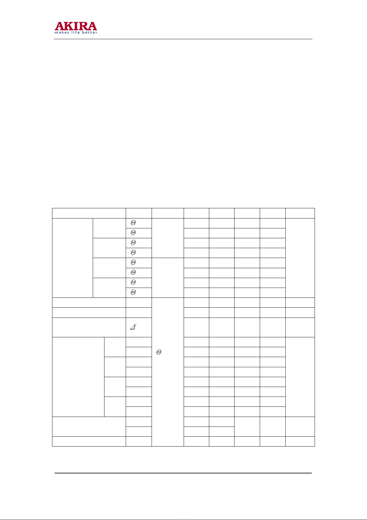
1. Viewing angle is the angle at which the contrast ratio is greater than 10. The viewing are determined
for the horizontal or 3, 9 o’clock direction and the vertical or 6, 12 o’clock direction with respect to
the optical axis which is normal to the LCD surface.
2. Contrast measurements shall be made at viewing angle of θ= 0° and at the center of the LCD surface.
Luminance shall be measured with all pixels in the view field set first to white, then to the dark
(black) state. (See FIGURE 1 shown in Appendix) Luminance Contrast Ratio (CR) is defined
mathematically.
CR = Luminance when displaying a white raster
Luminance when displaying a black raster
3. Center Luminance of white is defined as the LCD surface. Luminance shall be measured with all
pixels in the view field set first to white. This measurement shall be taken at the locations shown in
FIGURE 2 for a total of the measurements per display.
4. The White luminance uniformity on LCD surface is then expressed as : Y = Maximum
Luminance of five points / Minimum Luminance of five points (See FIGURE 2 shown in appendix).
5. The color chromaticity coordinates specified in Table 4. shall be calculated from the spectral data
measured with all pixels first in red, green, blue and white. Measurements shall be made at the center
of the panel.
6. The electro-optical response time measurements shall be made as FIGURE 3 shown in Appendix by
switching the “data” input signal ON and OFF. The times needed for the luminance to change from
10% to 90% is Td, and 90% to 10% is Tr.
7. Cross-Talk of one area of the LCD surface by another shall be measured by comparing the
luminance (YA) of a 25mm diameter area, with all display pixels set to a gray level, to the luminance
(YB) of that same area when any adjacent area is driven dark. (See FIGURE 4 shown in Appendix).