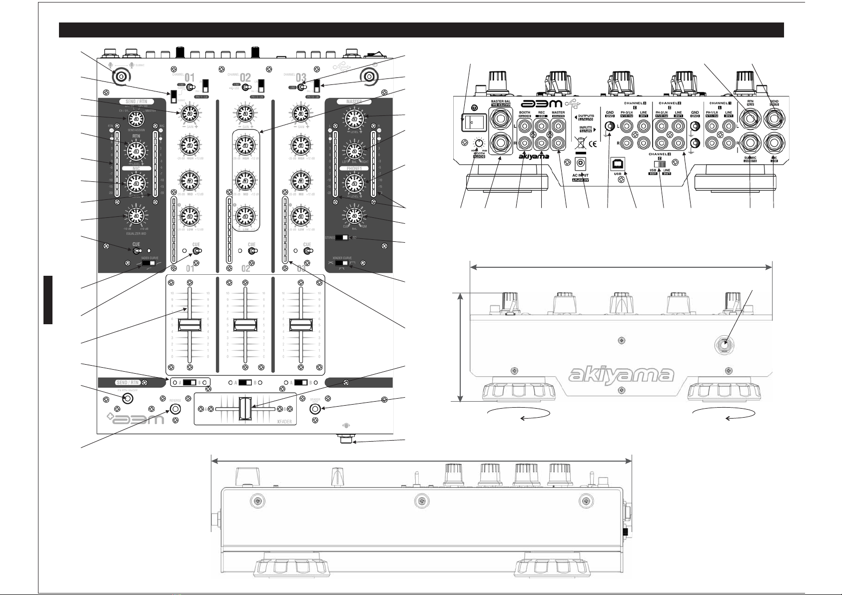
Akiyama A3M User manual

USER MANUAL
MANUAL DE USUARIO
WITH USB PLAYBACK/RECORD

1. Lea detenidamente este manual antes de utilizar su equipo.
2. Mantenga el manual a su disposición para su uso en el futuro.
3. Siga las advertencias que se le proporcionan en este manual.
4. Siga las instrucciones consignadas en este manual, un uso indebido podría dejar sin efecto la
garantía.
5. Agua y humedad. No utilice el equipo cerca del agua o en lugares muy húmedos (fregadero,
lavadora, etc.) para evitar riesgos de descarga eléctrica o fuego.
6.Transporte del equipo. Transporte el equipo con mucho cuidado. Los golpes o las vibraciones
fuertes pueden dañarlo mecánicamente.
7. Montaje en pared o techo. Siga las instrucciones del fabricante.
8. Fuentes de calor. Tenga cuidado de no colocar el equipo cerca de fuentes de calor (Ej. Radiadores,
estufas, mplificadores)
10. Protección del cable. Escoja una posición para el cable de corriente de modo que esté lo menos
expuesto a pisotones y demás agresiones. Especial atención con los dos extremos del cable de toma de
corriente, la clavija de enchufe a la red y la clavija de alimentación del equipo.
11. Limpieza. Desconecte el equipo antes de realizar alguna operación de limpieza del aparato. Utilice
un trapo suave y seco para limpiar. Asegúrese de que los cables están correctamente conectados antes
de volver a enchufar el aparato.
12. Control de seguridad. La diferencia de potencial entre la toma de corriente de la pared y cualquier
pieza metálica del equipo debe ser de al menos 100.000 ohmios.
13. Periodos largos de reposo del equipo. Desconecte el equipo de la red en caso de reposo prolongado.
14. Líquidos y objetos extraños. En caso de que algún fluido o pequeñas partículas sólidas sean
derramadas sobre el aparato y se introduzcan en los circuitos apague el aparato y llévelo a su
distribuidor.
15. Daños en el quipo que precisen reparación. El equipo deberá ser reparado o revisado por personal
cualificado en caso de:
A. El cable de toma de corriente o su conector han sido dañados.
B. Objetos o líquidos se han introducido en el equipo.
C. El aparato ha sido expuesto a la lluvia.
D. El equipo no parece funcionar o lo hace de modo poco usual.
E. E aparato ha caído al suelo o presenta deterioros en su caja exterior.
16. Mantenimiento. No abra el equipo para labores de mantenimiento pues en este aparato no hay
piezas que necesiten manutención. En caso de que abriendo el equipo sea éste dañado o lo sea la
persona que lo manipula la empresa no tomará ninguna responsabilidad por este servicio de
mantenimiento no autorizado.Además en éste caso la garantía perdería su vigencia.
17. Ventilación. El aparato está provisto de hendiduras de ventilación, es importante no cubrirlas o
bloquearlas. La ventilación del aparato podría verse comprometida resultando en un
sobrecalentamiento que podría dañar el equipo. Tenga siempre en cuenta que colocar el aparato en un
lugar sin ventilación puede producir un sobre calentamiento de éste.
18. Nunca utilice accesorios o modificaciones no autorizados por el fabricante. Ello puede afectar la
seguridad del aparato y el fabricante no tendrá ninguna responsabilidad en este caso.
19. Accesorios. No deposite o instale el equipo sobre superficies o estructuras inestables. El aparato
podría precipitarse y causar lesiones a las personas en las proximidades de éste. Cualquier montaje o
instalación del equipo deberá ser realizado siguiendo las instrucciones o recomendaciones dadas en
este manual o por el fabricante directamente.
20. Precaución durante tormentas. Durante una tormenta desconecte el equipo de la red para evitar que
los posibles picos de corriente dañen el equipo.
21. Durante cualquier manipulación del equipo, para mantener todas las cualidades de éste tanto en
prestaciones como en seguridad para el operante es necesario utilizar sólo recambios originales.
Consecuentemente asegúrese de que la empresa que realice el mantenimiento esté autorizada por el
fabricante o importador.
22. Comprobación de seguridad. Una vez realizada una reparación o servicio del equipo pida al
personal cualificado que realice una comprobación para asegurarse de que el equipo le es devuelto en
perfectas condiciones de uso.
9. Voltaje. Antes de conectar el aparato a la red asegúrese de que se trata del mismo voltaje y
frecuencia para las que el equipo está especificado. En caso contrario no conecte el equipo y
póngase en contacto con su distribuidor.
a
l
CAUTION
RISK OF ELECTRIC SHOCK
DO NOT OPEN
ATENCIÓN: para reducir el riesgo de electrocución, no
manipule el interior del equipo.
para realizar el mantenimiento del equipo póngase en contacto
con el personal cualificado
Esta señal indica la presencia de lugares donde
habiendo un elevado voltaje no presentan
aislamiento y por tanto constituye un claro
riesgo de electrocución.
Esta señal indica la presencia de componentes
del equipo que precisan de mantenimiento. Para
m s información sobre stos lea el manual.áé
ATENCIÓN
PARA EVITAR RIESGO DE ELECTROCUCIÓN ASEGÚRESE DE QUE EN CASO DE NO USAR UNA CONEXIÓN AC CON TOMA DE TIERRA LOS CONECTORES DE TOMA DE TIERRA DEL
ENCHUFE DEL MEZCLADOR NO QUEDEN EXPUESTOS.
1
ESPAÑOL

Antes de comenzar a utilizar su mezclador es muy importante que lea esta mínima introducción
escritaconelpropósitodeayudarleaobtenerelmáximopartidodesuequipo.
Ajustando el nivel de las señales de entrada: El potenciómetro etiquetado GAIN ajusta la
sensibilidad de la entrada de cada canal. Esto se realiza para ajustar el nivel de las señales de
entradaalnivel ptimodetrabajodelmezclador.
¿Por qu es importante ajustar correctamente el nivel de entrada? Primero deberemos entender el
significado e implicaciones del Rango Dinámico de la señal. El rango dinámico es el ratio o cociente
entre la señal más alta (sin llegar a distorsión) y la señal audible más baja. Se expresa en decibelios y
nos da una idea de la amplitud de la señal. Una medida equivalente es el ratio S/N (Signal/Noise o
Señal/Ruido).
El ni
Recuerde que si enviamos a la etapa de potencia una señal saturada del mezclador, aunque
atenuemos los controles de ganancia de entrada de la etapa la señal seguirá estando saturada.Y el
resultado de la amplificación no será satisfactorio pues estamos amplificando una señal ya
saturada.
Proteccióndeetapadepotenciaycajasacústicas
Respecto de la protección contra daños a su etapa de potencia no hay mucho que decir porque ésta
está diseñada de forma que sus distintos circuitos de protección la inmunizan de posibles
deterioros.Perosuscajasacústicasnodisponendeestasventajas…
¿Qué cajas pongo? Aunque parezca mentira no existe una regla precisa al respecto. Y, es que en
realidadnopuedeexistirtalregladado que todo dependerá del tipo de música que reproduzcamos.
Más en concreto, dependerá de su dinámica. ¿Qué es la dinámica de una señal? Anteriormente
hemos visto un gráfico Nivel vs. Tiempo de cómo se comporta la música o mejor dicho la señal
electroacústicaasociadaaésta.
Cuandomayor sea elrango dinámicomás deberemossobredimensionar la etapade potencia.¿Por
qué?Alser mayor el rango dinámicode la señal entrante (ésta presentagran diferencia de niveles a
lo largo del tiempo) la etapa puede llegar a saturación con facilidad, para evitar esta situación
debemos disponer de más potencia para poder amplificar eficientemente la señal entrante sin que
ésta sature la etapa (los LED “CLIP” de la etapa indican saturación). Por regla general podemos
considerar que la música rock y la música altamente comprimida necesitarán unas cajas acústicas
con una capacidad de potencia sólo algo inferior a la capacidad de la etapa de potencia, aunque
nosotros recomendamos que se aplique un factor de 1 5. Es decir, si nuestra etapa proporciona
200WRMS a 8Ω, la caja acústica deberá tener una capacidad de 200x1/1,5=133,4WRMS a 8Ω.
Para una óptima utilización del conjunto etapa-cajas el factor de sobredimensionado de la etapa
deberá ser de 2. Es decir, una etapa de 200 WRMS a 8Ω por canal alimentará a dos cajas de 8Ω con
capacidadpara100WRMS cada una.
Operacióndelaetapadepotencia:Saturaciónynivelesdeentrada
P
aturación.
Mezclador
Alimentadorexterno
UnaluzLEDconconexiónRCA
Manualdeinstrucciones
CONTENIDODELACAJADESUEQUIPO
ó
vel de la señal de audio deberá oscilar entre un
nivel lo más elevado posible respecto del ruido de
fondo y suficientemente menor que el nivel de
saturación. En el dibujo se ha delimitado el área o nivel
detrabajoóptimomediantedos
ue mantiene el
nivel de la señal suficientemente alejado del ruido de
fondo y permite que los picos de la señal no excedan el
límitedesaturación.
ara aprovechar al máximo la etapa deberemos ajustar los controles de nivel de entrada de modo
que los LED de saturación “CLIP” solo se iluminen ocasionalmente. Las etapas Akiyama AMP
tienen un nivel de entrada nominal de 4 dBu (es un nivel de señal de 1,23 VRMS que corresponde
al estándar de nivel de línea para uso profesional). Es decir, nuestras etapas trabajarán en óptimas
condiciones cuando la señal de salida de su mezclador hacia la etapa es de 4 dBu. La mayoría de
mezcladores profesionales tienen un nivel nominal de 4 dBu, así pues, para que la señal entrante
en la etapa sea la óptima simplemente asegúrese de no saturar la señal de salida del mezclador
(utilice los LEDs de nivel del mezclador). Lo adecuado es que los LED rojos (saturación) sólo se
enciendanocasionalmente.
¿Por qué debemos evitar la saturación? La señal saturada no sólo suena mal sino que puede
destruir nuestras cajas acústicas. No vamos a extendernos en este tema, simplemente utilice los
indicadoresLEDdelamesademezclasyetapadepotenciaparaevitarlas
é
líneasdiscontinuas.
El nivel de trabajo óptimo es aquél q
,
ESPAÑOL
2
Nivel mínimo audible
Pico (Transient)
Señal electroacústica
Tiempo
Nivel o amplitud
012345678
1
2
3
4
Ratio Nivel máximo vs. Nivel mínimo audible
Rango Dinámico
Rango Dinámico
15 minutos, ¡Léame!
SATURACION
SEÑAL
RANGO DINAMICO
HEADROOM
RATIO SEÑAL/RUIDO
!
RUIDO

DRAWINGS/DIBUJOS
3
17
280
101
374
ESPAÑOL
Desenroscando los apoyos
traseros podrá inclinar el
mezclador.
45
3
4
23
18
9
8
7
1
2
5
10
13
12
15
6
11
16
17
19
20
21
22
24
25
26
28
29
30
31 3233
34
35 43 4436 3738 40
39
14
41
42
27

4
SECCIÓN CANALES
SECCIÓN MASTER
SECCIÓN PREESCUCHA (CUE)
SECCIÓN VCA
SECCIÓN CROSSFADER
SECCIÓN ENVIO/RETORNO DE EFECTOS
Mediante la palanca de dos posiciones de cada canal decidimos
qué fuente reproductora est activa de las tres posibles
conectadasalcanal.
Se dispone de tres posibles selecciones función del canal:
Este control est ligado al control ( . Mediante la palanca de dos
posiciones de cada canal decidimos la fuente reproductora. En la
asignación derecha disponemos de un selector deslizante de dos
posiciones que nos permite seleccionar entre señal de L nea o
señal Phono.
En el canal uno, la selección izquierda de la palanca depende
del selector deslizante de dos posiciones que nos permite
seleccionar entre señal de Línea o Submic. Submic es el
micrófonoAuxiliar.
(
e recomienda mantener el
volumen de auriculares ( al mínimo antes de comenzar la
reproducción.
dos
pic metros de 10 leds cada uno. Miden el nivel de señal en un
rango de -20dB a +9 dB. Uno para cada canal, Izquierdo y
Derecho.
e recomienda mantener el volumen de auriculares al
mínimo antes de comenzar la reproducción.
I- E PGM la o las señales asignadas a la
salida Master mediante los ders de canal.
II-E la o las señales asignadas a
preescucha mediante los actuadores de palanca CUE de cada
canal.
(
(
1)
(1)
1)
15)
9)
24)
1
2
3
4
5
6
7
8
9
10
11
12
13
14
15
16
17
18
19
20
21
22
23
24
25
26
27
Phono
Mic
L
USB Línea
Control de ganancia :
Ecualizador de Canal:
Medidor de nivel de canal:
Conmutador de asignación de auriculares (CUE):
Atención
Fader de canal:
ATENCIÓN
Selector de Crossfader:
de nivel de Master:
Control de Balance:
Nivel de Señal de salida Master:
Selector Mono/Stereo:
Control de nivel Booth:
Control de nivel de auriculares.
Atención
Control panorámico de CUE:
Con or de auriculares :
Selector de curva de faders de canal:
elector de curva de Crossfader:
Control de Crossfader:
Control Reverse:
Control Crossfader ON/OFF:
Selector de fuente:
Control de nivel de retorno:
Medidor de nivel de :
Conmutador de asignación de auriculares (CUE):
Conmutador de ON/OFF de retorno:
Conmutadoresde asignacióndeentradas:
Conmutadores de asignación de entrada izquierda:
Conmutador Submic del canal 1:
(GAIN)
Control
ect
S
retorno
á
en
(giradiscos con cápsula MM)
on el mismo tipo de entrada)
o en el canal 2
Permite el ajuste de la
sensibilidad del canal de entrada en función de las distintas
fuentes. Para cada canal es posible realizar un ajuste óptimo
mediante la barra de LEDS .
Se dispone de un control
independiente para frecuencias altas (13KHz), medidas (1KHz) y
bajas (70Hz). Por favor advierta que cualquier banda de
frecuencia sobre elevada incrementará el nivel total y hará
decrecer el rango dinámico del equipo. Además, puede elevar el
nivel global de la señal hasta llegar a la saturación.
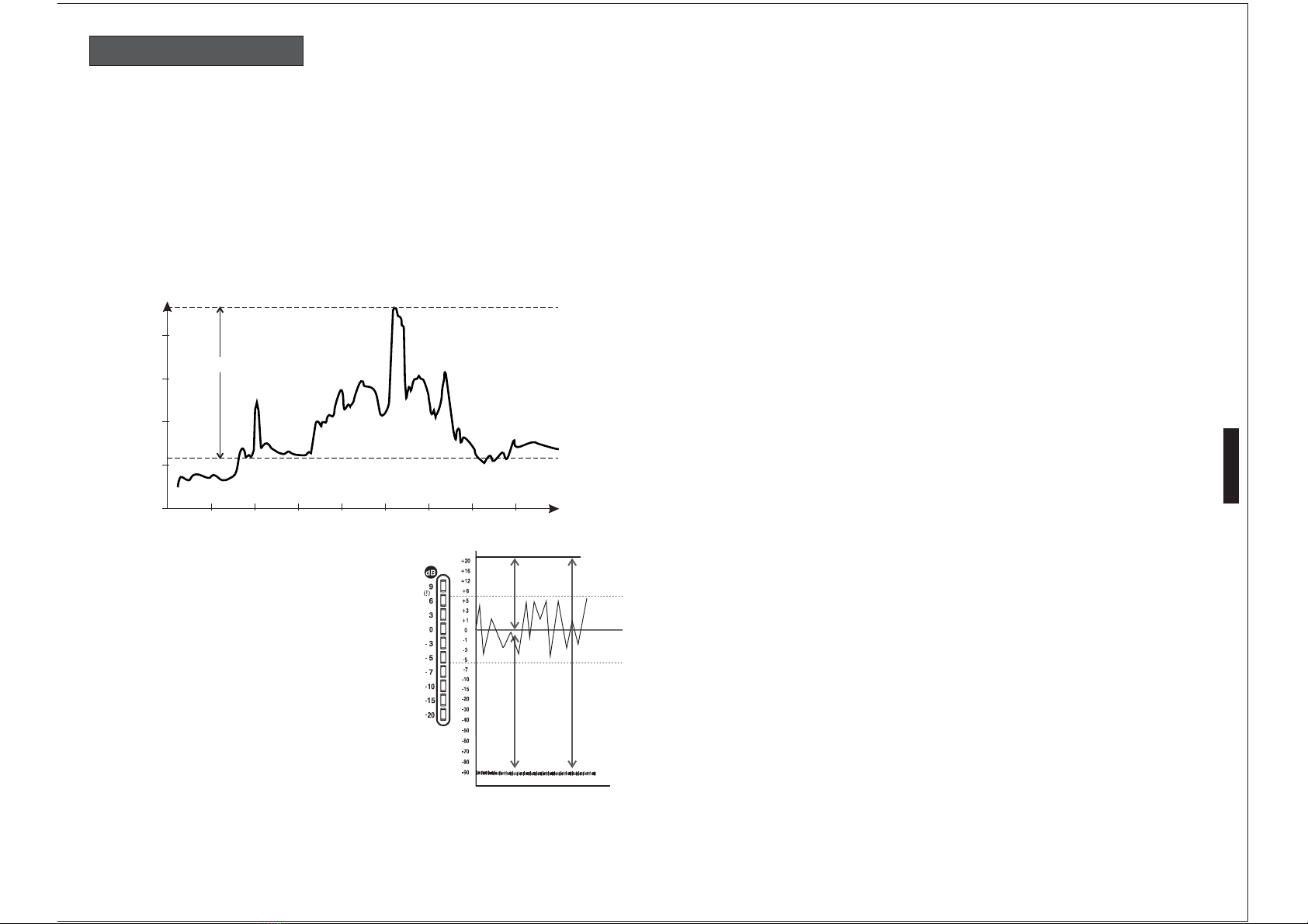
Nos indica el nivel de la señal en el
canal justo antes de la atenuación del fader. Para regular la
sensibilidad de entrada actúe sobre el control Gain de modo que
las luces verdes del medidor estén encendidas y las luces naranja
y rojas sólo se enciendan ocasionalmente.
Mediante estos conmutadores de palanca usted puede asignar
cualquiera de los canales de entrada para ser reproducidos a través
de los auriculares. Por favor advierta que sólo podrá escuchar la
fuente deseada si el conmutador de asignación de entradas
está conectado en su posición correspondiente y el equipo fuente
está reproduciendo. Observe que cuando esté activada se
iluminará un LED rojo. , s
Mediante estos controles, usted determina la
parte del nivel global al que un canal específico contribuye. Por
favor advierta que el nivel final de salida debe ser ajustado
mediante el Master y el Booth. Además el nivel de los canales
puede depender del Crossfader en caso de que el canal sea
direccionado al Crossfader.
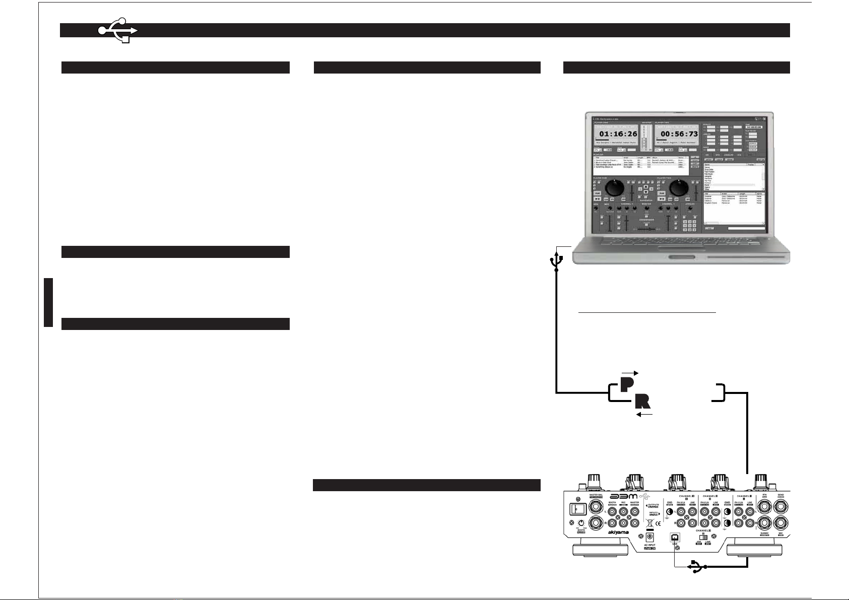
Para mayor operatividad y agilidad del equipo, el componente
mecánico donde se localiza la función de Crossfader y de Fader de
canal es reemplazable. Para reemplazar el Crossfader y/o el fader
de canal, desaloje los tornillos exteriores y retire la pieza;
desconecte el conector del cable y cambie la pieza. De la nueva
pieza conecte el conector del cable y atornille la nueva pieza del
equipo.
: para reemplazar el potenciómetro deberá primero
apagar el equipo y desenchufarlo de la red.
Nos permite enviar la señal del canal
a:
-A: Crossfader Izquierdo; LED (amarillo)
-B: Crossfader Derecho; LED (naranja)
Determina el nivel total de
señal de salida del mezclador.
Mediante el control Master
podemos enviar la señal al canal izquierdo o derecho de las dos
pistas estéreo.
Se dispone de
ó
Podemos transformar la señal de
salida, normalmente estéreo, en mono. En caso de que uno de los
dos canales (Izquierdo/Derecho) de salida Master se averíe este
control nos permite continuar la sesión, aunque en Mono.
Controla un amplificador externo
distinto al principal. Advierta que la señal no se muestra en el
medidor de nivel de señal de salida; consecuentemente, sea
prudente y no sobrecargue su amplificador.
Le permite controlar el
volumen en un auricular estéreo conectado al mezclador. Por
favor, asegúrese de que la impedancia del auricular sea como
mínimo de 32 Ohmios.Además, esté prevenido contra auriculares
de elevada impedancia que reducirán el nivel máximo de salida en
auricular. Se recomienda escoger un auricular con una
impedancia no superior a 200 Ohmios.
,s
Mediante esta función
podrá escuchar una mezcla entre las señales entrantes (señal
preseleccionada CUE) y la señal de salida Master (pre pot).
n posición : escuchamos
fa
n posición CUE: escuchamos
Conecte aquí sus auriculares. Se
trata de un conector Jack 6.3 TRS
Mediante este
conmutador de tres posiciones usted podrá determinar el modo en
que los fader de cada canal aumentan y disminuyen la señal en
función del recorrido que usted aplique al fader.
Mediante este
conmutador de tres posiciones usted podrá determinar el modo en
que el crossfader funde las señales (A) y (B) en función del
recorrido que usted aplique al fader.
Mediante este potenciómetro
deslizante podrá fundir las dos señales (A) y (B) asignadas a cada
uno de los lados del Crossfader mediante los selectores .
Conviene comentar que se dispone de tres curvas distintas de
fundido.
Mediante este botón podrá invertir la
polaridad del fundido del Crossfader.
Mediante este botón podrá
activar o desactivar el Crossfader. Con Crossfader activo el LED
rojo se ilumina. En algunos casos se preferirá no utilizar el
Crossfader, en estas condiciones se recomienda desactivarlo para
no quedarse sin sonido en caso de que el Crossfader este situado
donde no debe...
Mediante este conmutador rotativo podrá
escoger que fuente envía a efectos. Puede enviar
independientemente cualquier canal o la suma de estos
seleccionando Master.
Mediante este control podrá
determinar el nivel de la señal retornada por el módulo de efectos
externo.
Nos indica el nivel de la señal
retornada por el m dulo de efectos externo. Para regular la
sensibilidad de entrada actúe sobre el control de modo que las
luces verdes del medidor estén encendidas y las luces naranja y
rojas sólo se enciendan ocasionalmente.
Mediante esta función podrá enviar a pre-escucha (auriculares) la
señal retornada del m dulo de efectos. Así como la señal del
micrófono principal. Observe que cuando esté activada se
iluminará un LED rojo.
Mediante este
conmutador podrá enviar la señal de retorno (normalmente
efectos) al bus Master del mezclador. Al activarse se ilumina en
verde.Actúa como el habitual control “Effects ON/OFF”.
+ info pag.6-7
+ info pag.6-7
Balance
+ info pag.7
+ info pag.7
+ info pag.7
+ info pags.6/8
de
ínea (CD y Línea s
á
í
ó
ó
CONTROLES Y FUNCIONES
ESPAÑOL

ESPAÑOL
5
SECCIÓN MAIN MIC -MICRÓFONO PRINCIPAL-
SECCIÓN CONEXIONES SEÑALES DE ENTRADA
SECCIÓN CONEXIONES SEÑALES DE SALIDA
SECCIÓN DE SUMINISTRO EL TRICO
SECCIÓN ILUMINACIÓN
AJUSTE DE LA SENSIBILIDAD DE ENTRADA EN CANALES
()
()
(1) ( )
(1 )
()
(1)
El potenciómetro GAIN ajusta la sensibilidad de la entrada de cada canal. Esto se realiza para ajustar
el nivel de las señales de entrada al de trabajo del mezclador. El preamplificador de
entrada de cada canal nos permite variar el nivel de la señal.
Para ajustar la sensibilidad de entrada deberemos ajustar el nivel de GAIN tal que el Picómetro o
medidor de nivel de señal del canal correspondiente indique un valor estable próximo a 0 dB. Por
encima de este valor podemos saturar el equipo, aunque es tolerable ver ocasionalmente encenderse
los LEDs rojos. Esta operación deberá realizarse para cada uno de los canales del mezclador, pues las
fuentes de entrada pueden tener niveles considerablemente distintos.
Ade debemos tener en cuenta que el Picómetro nos da la lectura de nivel de la señal después del
ecualizador. Esto significa que debemos tener en cuenta que al incrementar algún nivel de frecuencia
mediante el ecualizador de canal podemos saturar el equipo. En este caso debemos volver a ajustar
el nivel de ganancia” Gain”.
Cuando tengamos dos canales enviados a Master simultáneamente sus señales se sumarán y en
Master podemos tener saturación. Deberemos asegurarnos que los medidores de nivel de Master
están correctamente ajustados y en caso de que indiquen saturación deberemos disminuir el nivel de
la señal.
IMPORTANTE: Recuerde que si enviamos a la etapa señal saturada del mezclador, aunque
atenuemos los controles de ganancia de entrada de la etapa la señal seguirá estando saturada. Y el
resultado de la amplificación no será satisfactorio pues estamos amplificando una señal ya saturada.
6
28
30
31
32
33
34
35
36
37
38
39
40
41
42
43
44
45
Control de nivel de Micrófono principal:
Ecualizador de Micrófono:
Medidor de nivel de Micrófono:
Conexiones de entrada a canales:
Conexión de entrada de Micrófono principal:
Conexión de entrada de Micrófono secundario -Submic- :
Conexión de retorno de efectos -RTN- :
Conexión de tierra para giradiscos:
Conexión de salida de Master Balanceado:
Conexión de salida de Master:
Conexión de salida de Booth:
Conexión de envío de efectos -SEND- :
Conexión de grabación -REC- :
Conmutador de puesta en marcha POWER:
Atención:
Conexión para el adaptador externo:
ConectorUSB:
Selector Línea/USB en CH-2 :
Conector RCA para luz LED:
Determina el nivel de la señal del micrófono
principal.
29 Es un control de tono (ecualizador) diseñado específicamente para
realzar las frecuencias en las que se circunscribe la voz humana. Dispone de un rango de actuación
+10dB a -10dB. Nos indica el nivel de la señal emitida a través de canal de
micrófono. Para regular el nivel de señal actúe sobre el control de modo que las luces verdes del
medidor estén encendidas y las luces naranja y rojas sólo se enciendan ocasionalmente.
El canal SEND/RETUN-MAIN MIC envía tanto la señal de retorno de efectos como la señal de
Micrófono principal a “Progam” o lo que es lo pre-fader .
Cada canal dispone de dos entradas mediante conectores
RCA. La entrada con la rúbrica Line es exclusivamente para señal de nivel de l nea, la entrada con la
rubrica Line/Phono puede acomodar ambos tipos de señal en función de la selección que realicemos
en el conmutador deslizante .
Se dispone de una entrada mediante conector
Jack 6.3 TS (Tip Sleeve) mono. Esta señal es conducida a los controles Main Mic.
Se dispone de una entrada
mediante conector Jack 6.3 TS (Tip Sleeve) mono. Esta señal es conducida al canal 1 mediante los
controles de selección de entrada y .
Se dispone de una entrada mediante conector Jack 6.3
TRS (Tip Ring Sleve) estéreo. Esta señal es conducida a los controles de retorno de efectos.
Se dispone de tres o cuatro (según modelo) conectores de
rosca donde debe fijarse las tomas de tierra de los giradiscos. Es importante no obviar esta conexión
pues su omisión producirá molestos ruidos.
Se dispone de una salida mediante conectores Jack
6.3 TRS (Tip Ring Sleve) estéreo. Esta conexión est concebida para conectar el mezclador a un
amplificador situado a cierta distancia (+ 3 m). El cable de conexión actúa como una antena que capta
todo tipo de radiaciones que en el caso de un cable largo pueden deteriorar la señal. El sistema de
balanceo electrónico de esta salida Master anula los posibles ruidos inducidos en el cable.
Se dispone de una salida mediante conectores RCA estéreo. Al
no disponer de un sistema de balanceo electrónico de la señal se recomienda utilizar esta salida cuando
el cable que conecta mezclador y amplificador no es largo (3m aprox.).
Se dispone de una salida mediante conectores RCA estéreo.
Controla un amplificador externo mediante el mando que en principio debería estar en la cabina
del Disk Jockey. Advierta que la señal no se muestra en el medidor de nivel de señal de salida;
consecuentemente, sea prudente y no sobrecargue su amplificador.
Se dispone de una salida mediante conector Jack 6.3
TRS (Tip Ring Sleve) estéreo. La señal que enviaremos a través de este conector dependerá de la
selección en el control .
Se dispone de una salida mediante conectores RCAestéreo.
El nivel de dicha salida es fijado de modo que es algo inferior al nivel de salida estándar del mezclador.
Es una salida dedicada exclusivamente a grabar las sesiones.
Una vez conectado el adaptador a la red AC.
Accionando el conmutador power switch el aparato será puesto en marcha. Mediante una segunda
acción sobre el conmutador el aparato se apagará. Varios LEDs se iluminarán cuando el aparato esté en
funcionamiento; por favor advierta que estos LEDs no se apagarán inmediatamente al desconectar el
equipo, debido a que el condensador debe descargarse antes.
Tenga siempre la precaución de enchufar primero el mezclador y a continuación el
amplificador para evitar que el ruido de conexión dañe sus altavoces; para apagar el equipo, apague
primero el amplificador y a continuación el mezclador.
Conecte aquí el cable del adaptador externo.
Conecte aquí el cable USB del ordenador.
En función de la posición del selector seleccionados Línea
o USB Input.
Se dispone de dos conectores RCA que alimentan una luz LED.
Son orientables y le permitirán iluminar el mezclador a su discreción.
nivel óptimo
más,
28
2
3
4
23
ÉC
mismo: Master
í
á
+ info pág 7
PANEL DE CONEXIONES
MANEJO DEL MEZCLADOR
IDIDID

6
ESPAÑOL
ENVIO/RETORNO DE EFECTOS
MICRÓFONOS
PREESCUCHA (CUE)
ECUALIZACI N
En primer lugar vamos a analizar los conectores SEND y
RETURNdenuestromezclador:
Ambas señales (Derecha e Izquierda) son conducidas por el
mismo cable. En función de las conexiones del de
efectos externo tendremos que utilizar un tipo de terminal
otr . El sistema de envio/retorno esta diseñado para funcionar
conmódulosdeefectose .
Veamos las conexiones de módulos de efectos que podemos
encontrarenelmercadoactualmente:
-ConexionesRCAe reo:
-ConexionesJack6.3 o:
-ConexionesJack6.3mono:
ATENCIÓN: nunca una las dos señales (Left, Right)
directamente,podriaprovocarde
Para ajustar el nivel de entrada de las señal de retorno
disponemosdelcontrol(24) ydelabarradeLEDs (25) que nos
permiten adaptar en nivel de entrada conforme a las
instrucciones dadas para optimizar el nivel de una señal
utilizando el control de nivel y la barra de LEDs. Es importante
que el nivel de entrada establecido sea el correcto para evitar
saturación.
Disponemosde dos entradas demicrófono, laprincipal MICy la
secundaria SUBMIC en distintos canales. La entrada SUBMIC
es asignable al canal 1 mientras que la entrada MIC dispone de
uncanalespec ficoparamicrófono.
Para conectar los micrófonos usamos conectores Jack 6.3 TS
(mono).Tal como el del dibujo.
e recomienda
mantener el volumen de auriculares al mínimo antes de
comenzarlareproducción.
Se dispone control (16) que nos permite fundir las señales
CUEyPROGRAM. Siendo la señal PROGRAMla señal Master
prefader, es decir ante
cos en función
delaposicióndelcontrol (16).
ATENCIÓN: Es importante entender que el amplificador
para cascos de este mezclador es suficientemente potente como
para provocarle un problema auditivo severo. Es por ello que le
rogamos utilice el nivel o volumen de los cascos con
moderación.
Se dispone de un potente ecualizador por canal tipo Sallen
Key/Butterworth de pendiente 18 dB/Octava con efecto Kill.
LosgráficosNivel/Frecuenciason:
!
!
HIGH
MID
módulo
ú
stéreo
sté
estére
sperfectosensumezclador.
í
Mediante estos conmutadores de palanca usted puede asignar
cualquiera de los canales de entrada para ser reproducidos a
través de los auriculares. Por favor advierta que sólo podrá
escuchar la fuente deseada si el conmutador de asignación de
entradas está conectado en su posición correspondiente y el
equipo fuente está reproduciendo. , s
del
s del fader de Master. En el dibujo
siguiente se explica que señal se escuchará en cas
Atención
Ó
a
Necesitaremos un adaptador con dos cables/conectores de Jack
6.3TRS a dos RCA
NecesitaremosdoscablesconconectoresJack6.3TRS
Necesitaremos un adaptador con dos cables/conectores de Jack
6.3TRS a dos JackTS.
El control de ecualización por canal etiquetado HIGH modifica
la señal de canal potenciando o decreciendo el nivel de la señal a
partirde un valor de frecuenciafijo, K Hz, enadelante hasta el
nivelaudiblemáximo.
El rango de intensidad operativo es de -26dB a +12dB con efecto
KILL..
De este modo podremos modificar la música reproducida dando
preponderancia o anulando aquellos instrumentos que resultan en
sonido de alta frecuencia como voces, guitarras eléctricas, charles
y otros.
13
MODULO DE EFECTOS ESTERO
T
R
S
+
+
+
+
SHIELD
SEND
RETURN
Jack 6.3 TS
T
S
SHIELD
T
S
+
SHIELD
T
S
SHIELD
T
S
SHIELD
T
R
S
+
+
+
+
SHIELD
T
S
SHIELD
T=CANAL DERECHO
R=CANAL IZQUIERDO
S=
SHIELD o GROUND
+
SHIELD
+
I D I D
Escucharemos Master
prefader en esteréo
Escucharemos CUE en
ester oé
I D
Escucharemos una
mezcla de ambas señales
T
T
R
R
S
S
+
+
+
+
SHIELD SHIELD
T
T
R
R
S
S
+
+
+
+
SHIELD SHIELD
SEND
RETURN
Jack 6.3 TRS
+
SHIELD
+
RCA
RCA
T=CANAL DERECHO
R=CANAL IZQUIERDO
S=
SHIELD o GROUND
+
SHIELD
+
RCA
RCA
SEND
RETURN
T
S
+
SHIELD
-70
+10
-60
-50
-40
-30
-20
-10
+0
20 20k50 100 200 500 1k 2k 5k 10k
Hz
dB
Minimum
Maximum
-70
+10
-60
-50
-40
-30
-20
-10
+0
20 20k50 100 200 500 1k 2k 5k 10k
Hz
dB
Maximum
Minimum
MODULO DE EFECTOS ESTEREO

El control de ecualización por canal etiquetado MID modifica
la señal de canal potenciando o decreciendo el nivel de la señal
alrededoraunvalordefrecuenciafijade Hz.
El rango de intensidad operativo es -26dB a +12dB con efecto
KILL.
De este modo podremos modificar la música reproducida dando
preponderancia o anulando aquellos instrumentos que resultan en
sonido de media frecuencia.
El ecualizador de media frecuencia es habitualmente considerado
como el más dinámico debido a que las frecuencias que definen un
sonido particular acostumbran a existir precisamente en el nivel
medio del espectro de frecuencias.
El control de ecualización por canal etiquetado LOW modifica
la señal de canal potenciando o decreciendo el nivel de la señal
en la zona de bajas frecuencias a partir de una frecuencia fija de
Hz. Tal como puede apreciarse en el gráfico.
El rango de intensidad operativo es de -26dB a +12dB con efecto
KILL. De este modo podremos modificar la música reproducida
dando preponderancia o anulando aquellos instrumentos que
resultan en sonido de baja frecuencia como la batería,
sintetizadores graves, el bajo de cuerda y en algunos casos las
voces si son suficientemente graves.
.
1K
70
LOW
CURVAS VCA
CAMBIAR POTENCIÓMETROS
ILUMINACIÓN POR LEDs
CURVAS DE CANALES
Podemos escoger entre tres modos o curvas de actuación de l
faders de canal respecto del desplazamiento del fader. En el
dibujo contiguo se representan dichas curvas donde podemos
vercomocambialaformaenqueelfa
CURVAS DE CROSSFADER
Curva SOFT
Curva MID.
Curva SHARP
. Corresponde a la posición del control (19) tal
como se indica en el dibujo. Es la curva apropiada para trabajar
con música Dance (entendemos por música Dance la música
basada en un
ha
ajustado correctamente el control Gain (4).
Corresponde a la posición del control (19) tal como
se indica en el dibujo. L
. Corresponde a la posición del control (19) tal
como se indica en el dibujo. Con un mínimo movimiento del
crossfader desde un u otro extremo de su recorrido, el canal
asignado al lado opuesto
ar scratch tipo "crabbing".
Dispondremos de un punto de corte muy definido en el que se
realiza una súbita conmutación de un canal a otro.
deractúa.
Para mayor operatividad y agilidad del equipo, todos los faders
delequi sporelusuario.
- Para reemplazar el Crossfader desaloje los tornillos exteriores
y retire la pieza; reemplace el fader co
se indica en el
dibujo. A continuación atornille el conjunto siguiendo el
procesoinverso.
: para reemplazar el potenciómetro deberá primero
apagar el equipo y desenchufarlo de la red.
Beat más o menos constante). Si disponemos el
crossfader totalmente a la izquierda escucharemos el canal
escogido en el banco izquierdo a máximo volumen. Si movemos
el crossfader de izquierda a derecha, gradualmente el canal
izquierdo irá decreciendo su presencia y el canal derecho irá
aumentando su presencia. Al llegar al extremo derecho tendremos
el canal derecho a volumen máximo. La traslación de un canal a
otro se realizar uniformemente. Con este tipo de curva
tendremos un buen control del volumen de los canales fundidos y
el nivel de señal de salida será constante (si previamente se
a curva de fundido adoptará la forma del
dibujo, el fundido de las señales izquierda y derecha es m
rápido que en el caso anterior.
aparecerá a máximo volumen. En esta
configuración podremos realiz
ATENCIÓN
El sistema de Control de Voltaje por Amplificador (VCA)
controla el nivel de faders de canal y crossfader de forma que l
os
posónfácilmentereemplazable
nectándolo tal como se
indica en el dibujo. A continuación atornille el conjunto
siguiendoelprocesoinverso.
- Para reemplazar un fader de canal desaloje los tornillos
exteriores de la placa común a los faders de canal y retire la
pieza; reemplace el fader conectándolo tal como
Se dispone de dos puntos de luz por LED. Para activarlos
sencillamente conecte el sistema LED en uno de los dos
conectores RCA que encontrará en la parte superior del
mezclador. Automáticamente se iluminarán. Podrá ajustar el
puntodeluzgirandoelsistemaLEDaderechaoizquierda.
Este sencillo sistema le permitirá iluminar el mezclador
mediante un sistema integrado en éste y que no interfiere
ergonómicamenteen la manipulación del mezclador.
El ángulo de apertura de iluminación del LED está restringido
para no molestar al usuario. Si, no obstante, desea menos luz,
levante la parte trasera del mezclador mediante los apoyos
giratorios.
a
señal audio no pasa por el potenciómetro, sólo es controlada por
éste. Esto significa que el deterioro mecánico de los
potenciómetros no afectará a la calidad de la señal. Podremos
variarlacurvadeactuacióndeéstosavoluntad.
á
ás
ESPAÑOL
7
-70
+10
-60
-50
-40
-30
-20
-10
+0
20 20k50 100 200 500 1k 2k 5k 10k
Hz
dB
Maximum
Minimum
Off
0dB
DESPLAZAMIENTO
NIVEL
Off
0dB
DESPLAZAMIENTO
NIVEL
Off
0dB
DESPLAZAMIENTO
NIVEL
Off
0dB
Off
0dB
Off
0dB
DESPLAZAMIENTO
NIVEL
NIVEL
NIVEL
DESPLAZAMIENTODESPLAZAMIENTO

8
ESPAÑOL
FUNCION ENVIO RETORNO (SEND - RETURN)
A- ENVIO/RETORNO A UN MODULO DE EFECTOS EXTERNO
B- “RETURN” COMO CANAL AUXILIAR
Primero es necesario realizar la conexión entre mezclador y módulo de efectos. Como las
posibles conexiones han sido examinadas en la página 6 en este apartado usaremos una sola de éstas. En
el dibujo vemos las conexiones adecuadas. A continuación se enuncia cronológicamente las acciones a
realizar.
Primero, utilizando el control (23), escogemos uno de los Canales o Master para ser enviado al módulo
de efectos. A3M permite enviar Ch1, Ch2, Ch3 y Master. A4M permite enviar Ch1, Ch2, Ch3, Ch4 y
Master.
La señal escogida es enviada al módulo de efectos a través del conector Send. El módulo de efectos
“colorea” la señal original y la devuelve al mezclador a través del conector Return.
Acontinuación debemos monitorizar la señal entrante, podemos monitorizar visual y acústicamente. La
barra de LEDs (25) representa el nivel de la señal entrante. Los auriculares nos proporcionan una pre-
escucha.
Barra de LEDs (25): Mide el nivel de la señal entrante. El nivel de esta señal es establecido por el
control de nivel de salida del módulo de efectos y por el control de retorno (24) del mezclador.Ajuste el
nivel de entrada siguiendo las instrucciones que encontrará en la página -15 minutos Léame!-. De este
modo evitamos saturación en la entrada del mezclador. Debemos tener en cuenta que al añadir la señal
Return a Master del mezclador el nivel global aumentará. Será necesario observar las barras de LEDs de
Master (12) para evitar saturación en la salida del mezclador.
Pre-escucha: Seleccione el control Cue (26). La señal entrante podrá ser escuchada en auriculares, se
comportara como una señal de canal con el control CUE activado. De este modo podremos determinar
el momento adecuado para activar el control FX ON/OFF.
Ahora que hemos establecido un nivel de entrada correcto de la señal Return y la pre-escuchamos con
auriculares podemos activar el control FX ON/OFF (27).
Effects ON/OFF: el botón (27) activa y desactiva el envío a Master de la señal Return. Mientras
monitorizamos la señal entrante el control (27) está en desactivado, OFF. Una vez hemos establecido el
nivel de entrada y estamos pre-escuchando la señal accionamos el control (27) para enviar a Master la
señal de retorno en el momento adecuado. El botón se iluminará en color verde.
Debemos tener en cuenta que la señal Return no está disponible en Crossfader.
Balance “Wet/Dry”: Llamamos “Wet” a la señal procesada por el módulo de efectos. Llamamos “Dry” a
la señal original enviada al módulo. Muchos de los últimos modelos de módulos de efectos disponen de
un control Wet/Dry incorporado. Si deseamos realizar la función “Wet/Dry” desde el mezclador
debemos actuar sobre los controles Return Level (24) y el fader del canal enviado a efectos.
Si no utilizamos un módulo de efectos la entrada Return puede ser utilizada como un canal estéreo extra
también llamado canal auxiliar. Convertiremos el modelo A3M en un mezclador de cuatro canales
estéreo y el modelo A4M en un mezclador de cinco canales estéreo. Debemos recordar que Return
dispone de monitorización visual y acústica.
Incluso podemos conectar la salida de un mezclador a la entrada Return de nuestro mezclador y mezclar
en tándem con otro Deejay.
correctamente
STEREO EFFECTS UNIT
Jack 6.3 TRS
B
A
APARATOS DE REPRODUCCIÓN
DE NIVEL LÍNEA
CD/MP3 PLAYER
USB PLAYER
SD PLAYER
MIXER MASTER
MD PLAYER
27
23
25
24
26
“RETURN” COMO CANAL AUXILIAR
ENVIO/RETORNO A UN MODULO DE EFECTOS EXTERNO

A- 43
.MP3 .WMA .WAV .AIFF.
B - Utilización del USB:
43
USB.
USB.
NOTA: ASEGÚRESE DE CONECTAR JUNTOS EL CHASIS
DELMEZCLADORYELDELCOMPUTADORATIERRA.
43
Apple
SYSTEM PREFERENCES
Sound”
OUTPUT
INPUT box
CODEC USB USBAUDIO DEVICE
Apple
SYSTEM PREFERENCES
Sound”
Sound Effects”
PLAYALERTS & SOUND EFFECTS”
SOUND
43
STARTMENU
CONTROLPANELS
SOUNDS &AUDIO DEVICES
AUDIOTAB
SOUND PLAYBACK
CODEC USB
AUDIO CODEC [2]
SOUND RECORDING
CODEC
AUDIO USB AUDIO CODEC [2]
USE ONLY DEFAULT DEVICES
CONTROL PANEL
CONTROL PANEL SOUNDS & AUDIO
DEVICES
SOUNDSTAB
SOUND SCHEME NO
SOUND
OK
USB
Los mezcladores A3M y A4M n un
, , , , o Es importante tener en
cuenta que podrá grabar y reproducir simultáneamente.
La conexión USB de los mezcladores A3M y A4M es
el
- PC Windows XP, o XP Professional con al menos un Puerto
- Mac OS X con al menos un Puerto
- o mayor
1. Encienda el computador y el mezclador
2. Utilice un cable USB para conectar el puerto del mezclador con
el puerto USB del computador.
3. Seleccione el icono
4. Seleccione “ ”
5. Seleccione el icono “
6. Seleccione “ box” para la pre-escucha, mediante el
mezclador, del audio reproducido por el ordenador o “ ”
para grabar la sesión, realizada con el mezclador, en el computador.
7. Seleccione el o el “ ”
8. Puede comenzar la reproducción utilizando los programas iTunes,
Quicktime o cualquier otro programa de audio disponible en su
ordenador. Si desea que los efectos de sonido disponibles en el
software de su ordenador no sean reproducidos en el mezclador
transfiera la señal del ordenador a los altavoces propios del ordenador:
1. Seleccione el icono
2. Seleccione “ ”
3. Seleccione el icono “
4. Seleccione “
5. Seleccione “ mediante el
menú del ordenador.
6. Seleccione los altavoces internos del ordenador
7. Mantenga el icono “ ” abierto para un acceso rápido a esta
área.
1. Encienda el computador y el mezclador
2. Utilice un cable USB para conectar el puerto del mezclador con
el puerto USB del computador. Windows reconocerá e instalará
automáticamente los “drivers” necesarios para poder comenzar la
reproducción. En caso de que el mezclador no reproduzca la señal de
audio del ordenador:
1. Seleccione “ ”
2. Seleccione “ ”
3. Seleccione “ ”
4. Seleccione “ ”
5. Seleccione “ ” para que el audio el ordenador
sea reproducido a través del mezclador y escoja un o
en caso de que mas de un aparato de audio este
conectado.
6. Seleccione “ ” para que señales de audio
externas puedan ser grabadas en el computador y escoja un
o en caso de que mas de un aparato
de audio esté conectado.
7. Asegúrese de que la opción “ ”
no está activa.
8.Aplique los parámetros escogidos
9. Mantenga el icono “ ” abierto para un acceso
rápido a esta área. Si desea que los efectos de sonido disponibles en el
software de su ordenador no sean reproducidos en el mezclador
transfiera la señal del ordenador a los altavoces propios del ordenador:
1. En el Seleccione “
”
2. Seleccione “ ”
3. En la ventana de menú “ ” seleccione “
”
4.Aplique los parámetros escogidos
5. Seleccione “ ”
El mezclador es compatible con la mayoría de los programas de
edición de audio. Podrá grabar desde el puerto USB (43)
simultáneamente en el ordenador independientemente de la asignación
de puerto USB. La señal de salida de grabación “ ” será
enviada al ordenador a través del los puerto 43). Aun cuando el
conmutador de asignación (44) no esté seleccionado podrá grabar
en el ordenador. Simultáneamente mientras
dispone de puerto USB ( )
conectable a puertos USB 1.0 o superiores permitiendo tanto la
sesión utilizando cualquier software de edición como utilizar dicho
programa para el (reproducción) con archivos de los
formatos
compatible con
cualquier programa de reproducción de audio & media “player”.
Utilice puerto ( ) para reproducir archivos de audio con el mismo
tipo de control sobre ellos que dispondría en un reproductor de CD o
giradiscos. O puede grabar las sesiones en vivo utilizando casi
cualquier programa audio & media “player” para luego grabarlo en un
CD u otro soporte. puerto USB puede reproducir y grabar al mismo
tiempo, esta característica se conoce como
USB 1.1
()
()
grabar
Playback
Full Duplex.
RECORD
USB (
El
AHORA PODRA COMENZAR LA REPRODUCCION DESDE
CUALQUIER PROGRAMADEAUDIO EN SU ORDENADOR.
NOTA: AL UTILIZAR UN SOFTWARE DE AUDIO DEBERA
AJUSTAR LAS PREFERENCIAS DE DICHO SOFTWARE.
NOTA: AL AÑADIR AL SISTEMA EL MEZCLADOR MANIPULE
EL CONTROL DE VOLUMEN DEL SOFTWARE DE SU
ORDENADOR PARA QUE LA REPRODUCCION SE EFECTUE
DENTRO DE LOS NIVELES OPTIMOS DEL MEZCLADOR. EL
CONTROL DE VOLUMEN LO ENCONTRARA EN “AUDIO
SETTINGS”.
ESPAÑOL
9
TUTORIAL USB
REQUERIMIENTOS DEL SISTEMA
SISTEMAPARAMAC
SISTEMA PARA PC CONEXIÓN
GRABAR CON USB
INTRODUCCIÓN
Utilizando un laptop para reproducción y mezcla mediante
cualquier programa disponible en el mercado conectaremos laptop
a mezclador utilizando el conector USB del mezclador. Podremos
.reproducir y grabar la sesión al mismo tiempo
PC/MAC con PLAYBACK & REC SOFTWARE
USB
USB
SISTEMA FULL DUPLEX
LAYBACK
ECORD
PR

1. Read Instructions All the safety and operating instructions should be read before this product is
operated.
2. Retain Instructions. The safety and operating instructions should be retained for future reference.
3. Heed Warnings. All warnings on the appliance and in the operating instructions should be adhered
to.
4. Follow Instructions. All operating and use instructions should be followed.
5. Water and Moisture. The appliance should not be used near water - for example, near a bathtub,
washbowl, kitchen sink, laundry tub, in a wet basement, or near a swimming pool, and the like.
6. Carts and Stands . The appliance should be used only with a cart or stand that is recommended by
the manufacturer.
An appliance and cart combination should be moved with care. Quick stops, excessive force, and
uneven surfaces may cause the appliance and cart combination to overturn.
7. Wall or Ceiling Mounting. The product should be mounted to a wall or ceiling only as
recommended by the manufacturer.
8. Heat. The appliance should be situated away from heat sources such as radiators, heat registers,
stoves, or other appliances (including amplifiers) that produce heat.
10. Grounding or Polarization This product may be equipped with a polarized alternation-current
line plug (a plug having one blade wider than the other). This plug will fit into the power outlet
only one way. This is a safety feature. If you are unable to insert the plug fully into the outlet, try
reversing the plug. If the plug should still fail to fit, contact your electrician to replace your
obsolete outlet. Do not defeat the safety purpose of the polarized plug.
11. Power-Cord Protection. Power-supply cords should be routed so that they are not likely to be
walked on or pinched by items placed upon or against them, paying particular attention to the
cord in correspondence of plugs, convenience receptacles, and the point where they exit from the
appliance.
12. Cleaning - The appliance should be cleaned only as recommended by the manufacturer. Clean
by wiping with a cloth slightly damp with water.Avoid getting water inside the appliance.
13. For AC line powered units - Before returning repaired unit to user, use an ohm-meter to measure
from both AC plug blades to all exposed metallic parts. The resistance should be more than
100,000 ohms.
14. Non-use Periods. The power cord of the appliance should be unplugged from the outlet when left
unused for a long period of time.
15. Object and Liquid Entry. Care should be taken so that objects do not fall and liquids are not spilled
into the enclosure through openings.
16. Damage Requiring Service. The appliance should be serviced by qualified service personnel
when:
A: The power-supply cord or the plug has been damaged; or
B: Objects have fallen, or liquid has been spilled into the appliance; or
C: The appliance has been exposed to rain; or
D:The appliance does not appear to operate normally or exhibits a marked change in
performance; or
E: The appliance has been dropped, or the enclosure damaged.
17. Servicing. The user should not attempt any service to the appliance beyond that described in the
operating instructions.All other servicing should be referred to qualified service personnel.
18. Ventilation Slots and openings in the cabinet are provided for ventilation and to ensure reliable
operation of the product and to protect it from overheating, and these openings must not be
blocked or covered. The openings should never be blocked by placing the product on a bed, sofa,
rug, or other similar surface. This product should not be placed in a built-in installation such as a
bookcase or rack unless proper ventilation is the manufacturer's instructions have been adhered
to.
19. Attachments do not use attachments not recommended by the product manufacturer as they may
cause hazards.
20. Accessories Do not place this product on an unstable cart, stand, tripod, bracket, or table. The
product may fall, causing serious injury to a child or adult, and serious damage to the product. Use
only with a cart, stand, tripod, bracket, or table recommended by the manufacturer, or sold with
the product. Any mounting of the product should follow the manufacturer's instructions, and
should use a mounting accessory recommended by the manufacturer.
21. Lightning For added protection for this product during a lightning storm, or when it is left
unattended and unused for long periods of time, unplug it from the wall outlet and disconnect the
antenna or cable system. This will prevent damage to the product due to lightning and power-line
surges.
22. Replacement Parts When replacement parts are required, be sure the service technician has used
replacement parts specified by the manufacturer or have the same characteristics as the original
part. Unauthorized substitutions may result in fire, electric shock, or other hazards.
23. Safety Check Upon completion of any service or repairs to this product, ask the service
technician to perform safety checks to determine that the product is in proper operating condition.
9. Power Sources This product should be operated only from the type of power source indicated on
the rating label. If you are not sure of the type of power supply to your home, consult your
product dealer or local power company. For products intended to operate from battery power, or
other sources, refer the operating instructions.
CAUTION
RISK OF ELECTRIC SHOCK
DO NOT OPEN
CAUTION: To reduce the risk of electric shock, do not
remove any cover. No user-serviceable parts inside. Refer
servicing to qualified service personnel only.
The lightning flash with arrowhead symbol within the
equilateral triangle is intended to alert the use to the
presence of un-insulated “dangerous voltage” within
The exclamation point within the equilateral triangle is
intended to alert the user to the presence of important
operation and maintenance (servicing) instructions in
the literature accompanying this appliance.
WARNING
TO PREVENT FIRE OR SHOCK HAZARD. DO NOT USE THIS PLUG WITH AN EXTENSION CORD, RECEPTACLE OR OTHER OUTLET UNLESS THE BLADES CAN BE FULLY INSERTED TO PRESENT BLADE TO
PREVENT FIRE OR SHOCK HAZARD. DO NOTEXPOSE THISAPPLIANCETO RAIN OR MOISTURE. TO PRVENT ELECTRICALSHOCK, MATCH WIDE BLADE PLUG TOWIDE SLOT FULLY INSERT.
ENGLISH
1

Beforeunwrappingandstartingthemixerthereareafewthinksyoushouldknow…
Setting input levels: Gain pot adjusts the input sensibility or so to speak the level of the input
signalinsidethemixer. It is paramount to set the right input level on every channel.
Whyissoimportantsettingthecorrectinputlevel?
First, we have to understand the concept of Dynamic Range of an audio signal. The Dynamic
Range of an audio signal is defined as the ratio between the maximum level before distortion and
the minimum audible level. It is measured in decibels and gives us an idea of the amplitude of the
signal.
We want the audio signal to fluctuate away from the
maximum level (distortion begins) and away from the
minimum level (or background level), where some
noise is present due the nature of the ICs used in the
electronic circuit (all ICs induce noise into the audio
signal).
At the draw, we depict this “safe” level within two
discontinuelines.
We have to setthe level of input signal so thatthe signal
peaks do not reach saturation levels and the lower
amplitude parts of the signal are not too near the
backgroundnoiselevel.
We have to acknowledge that a professional audio system is a serial bounded group of
professional audio devices and that saturation or other signal deterioration present in one device
willappearsomewayoranotherattheserialboundedfollowingdevices.
If we deliver saturated signal from the mixer to the power amplifier we will not be able to get rid of
this saturation whatsoever. The power amplifier will amplify all what is given and if noise is given
(saturationatmixer),itwillbeamplified.Naturally,thatisbad.
Power amplifiers and loudspeakers: Current professional power amplifiers are quite reasonably
protected against signal deterioration and excessive levels and shortcuts. Loudspeakers are not
that well protected, hence a rule or some must be devised to use the correct speakers with a given
poweramplifier.
Well, that rule is not a straightforward statement but more of an understanding of the principles
and nature of the audio signal. The nature of the audio signal reefer to the type of music you are
playing and more specifically of its Dynamic Range. The bigger the Dynamic Range the bigger
the power amplifier needed. If the Dynamic Range of a give audio signal is big, the difference
between the minimum level and maximum level of this audio signal will be big as well. Therefore,
we will need an oversized power amplifier with enough power to amplify the maximum levels
without reaching the saturation level at the power amplifier (normally, power amplifiers have red
LEDstoletyouknowwhentheystartsaturating).
As a vague rule we can say that Rock and highly compress music require a power amplifier
deliveringapower value slightly bigger thanthe rated maximum powerof the speakers.However,
we recommend the power amplifier rated power be 1.5 times bigger than the rated maximum
power of the speakers. Example: if the power amplifier rated power is 200W RMS at 8 , the rated
maximumpowerofthespeakersshouldbe200x1/1,5=133,4WRMS at 8 .
Usingthepoweramplifier:Saturationandinputlevels.
Inordertomakethemostofyourpoweramplifieryoumustwatchtwothings:
1-SetthevolumecontrolsinawaythatthesaturationLEDlightsuponlyoccasionally(peaks).
2- Feed the power amplifier with an audio signal of the appropriate level. What is the appropriate
level? Professional PowerAmplifiers are set for an input level of 4 dBu. Do not panic, it is easy to
get to it. 4 dBu is just a fixed measure of the audio signal that professional audio community uses
as reference level, it can be expressed also in Volts 4dBu equals 1.23 Volt RMS. So to speak, the
Power Amplifier will work at its best if feed with a signal of a level near the 4 dBu or 1.23 Volt
RMS. How do we set this level? Easy, using the mixer appropriately. Incidentally, the nominal
levelfor a professional audiomixer is also4dBu. Therefore, if weset the masteroutput levelof the
mixer carefully monitoring the output level meters (normally LED bars), we will ensure that the
level of the audio signal fed to the PowerAmplifier is near 4dBu because the nominal level of the
mixeris4dBuandwesetcorrectlytheoutputlevelorthemixer.
Whyweshouldavoidsaturation?
Obvious reasons aside there is a more “material” reason. Saturated signal can damage your
speakers.Although some speakers have overload protection, a highly saturated signal can deliver
D.C.andthisphenomenoncaneasilyshatteryourspeakers.
Ω
Ω
ACCESSORIES
(1) Operating Instruction 1 pc
(2) Switching Adaptor 1 pc
(3) LED Searchlight 1 pc
ENGLISH
2
15 min, Readme!
Minimum audible level
Pic (Transient)
Electroacoustic Signal
Time
Level or amplitude
012345678
1
2
3
4
Ratio: Max. Level vs. Minimum audible level
Dynamic Range
Dynamic range
SATURA IONT
SIGNAL
DYNAMIC RANGE
HEADROOM
RATIO SIGNAL/NOISE
!
NOISE

DRAWINGS
3
45
3
4
23
18
9
8
7
1
2
5
10
13
12
15
6
11
16
17
19
20
21
22
24
25
26
28
29
30
31 32
33
34
35 43 4436 37
38
40
39
14
41
42
27
17
280
101
374
ENGLISH
Unscrewing the feet you will
be able to tilt forward the
mixer.

4
CHANNELS SECTION
MASTER SECTION
MONITORING SECTION (CUE)
VCA SECTION
CROSSFADER SECTION
SEND/RETURN SECTION:
Input Selectors
line or cd
phono
mic
Input sensibility control GAIN:
Channel Equalizer:
Balance :
Level meter:
Mono/Stereo Selector:
Booth level control:
Headphones level control:
Caution!
Return Level control
Return signal Monitoring
By means of the 2 position levers at each
channel choose the source to be assigned to the channel.
Accordingtothetypeofsignalwecanchoosebetween:
: This is a line lever signal. We can found it in CD
Players, MD Players, Cassette Players and other domestic
devices.
: We find this type of signal in Turntable cartridges.
Previous to be processed in the mixer is equalized by a RIAAfilter
included in the mixer.
: For microphone only.
And at Ch-2 we can select USB by means of control and control
.
GAIN sets input sensibility of each channel. By means of this
control we adjust input level to mixer optimum level. To set input
level turn GAIN pot until let BAR of respective channel
depicts around 0dB. Over this value we are close to saturation. This
task will have to be done for each of the channels because
differents inputs sources may have differents levels.
3 band equalizer is provided for each
channel. These 3 bands are set at High 13KHz, Mid 1KHz, Low
70Hz. Notice that when increasing any tone level we increase the
overall level of the signal and we can reach saturation. Is advisable
to watch carefully the output lever meters to avoid this situation.
Led bar displays signal
level relative to an optimal working level .
Will allow us to monitor input level. Level on Led bar is
independent from channel fader but will depend on GAIN and
Equalizer settings.
Red Leds light indicates saturation. Yellow Leds light indicates
near saturation. Green Led light indicates safe zone. Proper
setting is when red leds lights only in musical peaks for a short
lapse of time.
Set channel volume to master mix
¨0¨ position no signal is routed to Master bus. In “10” position,
100% of channel signal is routed to Master bus.
To be in-field replaceable,
this part is front-detachable. For replacement, switch off the unit
and unscrew the outer screws of the plate and remove the part;
detach the connector and replace the part. Plug in the connector
and screw the new part to the main body again.
The signal's stereo balance can be
controlled by means of control Balance Master
. This signal is displayed on the level meter.
The level meter shows the stereo
output level of Master output. Two ten segment LED bars are
available with -20/+9 dB range.
We can transform output signal,
normally stereo, in mono.
Controls
. Please note that the level of
this output will not in any case be displayed on the level meter;
consequently, please check carefully for your amplifier not being
overloaded.
With a stereo headphone
connected, you may control the headphones volume. Please check
your headphones impedance for a minimum of 32 Ohms and be
aware of high-impedance headphones reducing the maximum
output power of this output, so that you should choose a
headphone with less than 200 Ohms of impedance.
Set level carefully, output signal is powerful enough to
damage your ears. We recommend start setting from control
turned fully counter clockwise.
right
I- Control turn to PGM we heard the master mix pre Master
fader. Master mix will depend upon Channels faders setting.
II- Control turn to we heard the Channels with CUE toggle
activated.
When the control is in between the to extreme positions we heard a
blend of both PGM and CUE signals.
Adjust the mix volume of the sources selected to
left (A) and right (B) side. We can adjust crossfader curve shape by
means of control .
When is active a
LED lights up.
Switches ON/OFF the crossfader. For
those not using the crossfader, selecting OFF will make things
easier as signal by passes it. When Crossfader is active a Red LED
lights up.
Sets the level of returned signal
throught the Return connector. Monitoring of incomming signal is
done with the ten LED segment bar
ten LED segment bar depict
the level of Retun signal. To set properly the Return signal level act
upon control .
Red Leds light indicates saturation. Yellow Leds light indicates
near saturation. Green Led light indicates safe zone. Proper
setting is when acting upon control red leds lights only in
musical peaks for a short lapse of time.
When is active a LED lights up.
(1)
(44)
(1)
(1)
(6)
(19)
()
(24)
(25)
Please be aware of
the final output level to be adjusted by the Master and Booth
controls. Furthermore, the level of the channels can depend on the
setting of the Crossfader if these channels are assigned to it by
means of the Crossfader assign control.
:
Secondary Input selectors:
Channel 1 Submic selector:
Channel level meter:
Channel CUE assign toggles (CUE):
Attention:
Channel Fader:
Attention
Crossfaderassign:
Master level control:
control
Master
Cue Panoramic control:
Headphones connector :
Channel Faders curve selector:
Crossfader curve selector:
Crossfader:
Reverse Control :
Crossfader ON/OFF:
Source Selector:
:
:
Return CUE:
Return ON/OFF :
This control depends upon
control selection. Using the 2 position slide switch on each
channel we can choose between a Line and a Phono level input
signal.
At Channel 1 when Selector
is set to the left we can choose between 2 input signals, Line
and Submic that is the secondary Microphone input.
10 segment
(named nominal level)
Level setting:
Switching the toggles
we activate CUE on each respective channel. Meaning that the
signal of the channel will be available for headphones monitoring.
before starting monitoring keep the headphones level
at minimum. The mixer is fitted with a powerful output amplifier
that can damage your hearing.
s . While at
6
: Before performing this operation switch off your
mixer and unplugg it.
Foreachchannel we can send itssignal to:
-A: Left side of Crossfader (Yellow LED)
-B: Right side of Crossfader (Orange LED)
Sets the overall output level.
sending to left or
right modification
a secondary amplifier,
normally placed at the control room
By means of this function, you can
preview your forthcoming mix by crossfading between the
preselected headphones signal on the left side of the control and
the Master output signal (pre pot) on the side of the control.
:
CUE:
Plug your headphones at the Jack
6.3TRS.
Sliding this 3 position
control you can choose between three different curves for the
Fader action. From to the slope of the curve
increases.
Sliding this 3 position control
you can choose between three different fading curves between A
and B sources. From to the slope of the curve
increases.
Pressing this control you will switch
Crossfader left to Right and viceversa. Reverse
Yellow
This rotary switch allows to choose any
Channel or Master to Send signal.
25 .
This
RETURN Level setting:
Sends the return signal to headphones for
monitoring. As well as the Main Mic signal. Red LED will light
when function activated.
This control enables the return signal to
Master bus. So to speak is like an Return ON/OFF or Effects
ON/OFF. Return ON/OFF Green
+ info pag 7
SOFT SHARP
+ info pag 7
SOFT SHARP
+ info pag 7
+ info pag 6/8
CONTROLS AND FUNCTIONS
ENGLISH
2
7
10
1
3
4
5
6
8
9
11
12
13
15
16
14
17
19
18
20
21
22
23
25
26
27
24

5
MAIN MIC SECTION POWER SUPPLY SECTION
MIXER ILLUMINATION
SETTING INPUT/OUTPUT LEVELS
ten LED segment bar depicts the level of the Mic signal. To set
properly the signal level act upon control .
Red Leds light indicates saturation. Yellow Leds light indicates near saturation. Green Led light
indicates safe zone. Proper setting is when acting upon control red leds lights only in musical
peaks for a short lapse of time.
Intended for recording purposes. REC signal level is inferior to
mixer standard level to assure proper recording.
Before switching on, set Master fader at “0” position.
Follow this rule:
- When starting the session, the amplifier is last to switch on.
- When finishing the session, the amplifier is first to switch off.
Gain pot adjusts the input sensibility or so to speak the level of the input signal inside the mixer. The
input preamp (Gain) allows us voltaje level adjustment. It is paramount to set the right input level on
every channel.
Adjust the input level using the pot, set it using the LED bar as monitoring reference. Level
will be correct when LED bar red LEDs only light ocasionally in short time intervals. This operation
will have to be done independently on each channel because different audio sources can have a
different output level.
Also, be aware that the LED will depict the signal level after equalizer, therefore if we increase any
of the three tone controls we will have to check the LED bar for unwanted distortion due tone control
increase.
Same thing has to be done to adjust output level for Master. When more than one channel is at Master
mix both signals will add and the overall level will increase. This fact will be monitored through the
Master LED bars and the same channel setting procedure will have to be made using Master
fader as level control.
IMPORTANT: We have to acknowledge that a professional audio system is a serial bounded group of
professional audio devices and that saturation or other signal deterioration present in one device will
appear someway or another at the serial bounded following devices. Hence, distorted signal at mixer
output will be distorted all the way to loudspeakers.
)
(28)
()
(1) ( )
(1 )
(1)
Balanced Master output:
output
Two Balanced signals
are typically used to connect to the amplfier system for professional use. Specially when cable lines
are long and therefore can caught unwanted noise.
Connect to the amplifier system. Normally RCAoutput are used at
domestic setups or cable lines are short.
Gain
Microphone level:
Microphone equalizer:
Microphone level meter:
Channels Input connections:
Main Microphone Input:
Submic Input:
Return connection:
Turntable earth connections:
Un
Booth :
Send connection :
REC (recording) connection :
POWER switch:
Attention:
ExternalAC adapter connection:
USB connector :
CH-2 Line/USB selector:
RCA connectors for LED lights:
Sets the microphone level.
The Microphone equalizer is especifically designed for human voice
tone control.The control has a range of +10dB/-10dB.
This
Level setting:
Each channel is fitted with 2 RCA connector inputs. Line inputs
are for line level signal (CD Player, MD Player, MP3 Player analogue output, Cassette, etc.). Inputs
labeled Line/Phono can be fed with both types of signal according to the position of control .
A Jack 6.3 TS (Sleeve) mono is placed at rear panel for this signal.
Main Mic controls at front panel will act upon this signal.
A Jack 6.3 TS (Sleeve) mono is placed at rear panel for this signal. This signal is
directed to channel 1 by means of the input controls and .
A Jack 6.3 TRS (Tip, Ring, Sleeve) stereo is placed at rear panel for this
signal. controls at front panel will act upon this signal.
Three earth connector are available at rear panel. Fix the turntable
earth wire at these screws. If this operation is not done properly the audio signal will be parasite with
humming noise.
Jack 6.3 TS (Sleeve) are placed at rear panel.
This is a second Master output normally used type for monitoring at the DJ cabin
(when available). Its level is control by . As we dont have a monitoring system for this signal it is
important that you watch closely the amplifier connected to it to avoid saturation.
AJack 6.3 TRS (Tip, Ring, Sleeve) stereo is placed at rear panel for this signal.
controls at front panel will act upon this signal.
Plug the AC adapter to the mixer and then to the Mains net. Press the ON
switch and a some LEDs will light, another press and the mixer will be OFF as well as the LEDs. Be
advised that when switching off the LED will not light off immediately due time needed for capacitors
to unload.
Plug theAC adapter to the mixer at this connection.
Plug the USB cable from Computer to mixer .
Upon selector position select Liner or USB Input.
Two RCA connectors are available at top of front panel, plug
the LED lights provided with the mixer for instant lighting. Turn the LED lights at your will to get the
best angle.
(6)
(12)
(28
2
3
4
INPUTS SECTION
OUTPUTS SECTION
Return Level
Send Assign
+ info at page 7
CONNECTIONS PANEL
HANDLINGTHE MIXER
ENGLISH
34
35
36
37
38
39
40
28
29
30
31
32
33
41
42
43
44
45

SEND/RETURN
MICROPHONES
HEADPHONE MONITORING (CUE)
EQUALIZATION OR TONE CONTROL
First we will have a look at the differnt connectors for Send and
Returnfunctions.
Now we will review different audio devices according totheir
connections:
-RCAstereo connections:
- Jack6.3stereoconnections:
- Jack6.3monoconnections:
Jack 6.3 TS are the chice of connectors for the microphones.
FollowingaschematicofaJack6.3TS:
High equalizing control increases and decreases high frequency
band signals. Range is from -26 dB to + 12 dB. Typical high
frequency signals are voices, electric guitars, charles and
others.
Mid equalizing control increases and decreases mid frequency
band signals. Range is from -26 dB to + 12 dB. Mid range equalizer
is regarded as the most dynamic of all because the defining
frequencies of an audio signal do usually occur in the mid range
frequencies.
!ATTENTION: never attempt to tie up both signals Left and
Right,thiscandamageyourmixer.
To set a proper entry level for Return signal we use control
e
correctlevelasseeatintroductorypage.
Acting upon the lever switches you activate and deactivate the
channel Cue function, which enables hearing the signal through
the headphones. Before performing a Cue check the channel is
feedwithaplaybackdeviceandthatisON.
Control 16 fades between CUE and PROGRAM signals. Program
signal is the signal present at Master bus, so to speak the signal
available at Master fader. Following draw depicts signal
distribution at headphones.
ATTENTION: Set headphones at minimum before
performing a Cue, the powerful headphone amplifier could
damageyourhearingisimproperuse.
We have a really accurate equalizer at AM mixers. A Sallen
Key/Butterworth, 18dB/Oct slope and KILL Effect. This is a
accurately crafted equalizer with a magnificent frequency
response as it will be seen at the following graphics. Bear in
mind that these graphics are directly taken from the analyzer
apparatus therefore some minor deviations from perfect
responsecanoccur.
High labelled tone control modifies signal level around a fix
frequency13KHz.
Mid labelled tone control modifies signal level around a fix
frequency 1 KHz.
!
HIGH
MID
Bothsignals, left and right,will be driventhroug thesame cable.
Different external audio devices have different connections and
we will have to adapt to them. However, bear in mind the the
mixer has been designed to be connected to stereo external
devices.
Two microphone inputs are at hand, MAIN MIC and SUBMIC.
Main Mic has a specific channel plus voice equalization.
Submicisselectedatchannelone.
(24)
for level setting and through monitoring LED (25) we adjust th
We will need an adaptor for Jack 6.3 TRS to two RCA
connectors.
Two Jack6.3TRS cables will be needed.
We will need an adaptor for Jack 6.3 TRS to two Jack TS
connectors.
6
MODULO DE EFECTOS ESTERO
T
R
S
+
+
+
+
SHIELD
SEND
RETURN
Jack 6.3 TS
S
SHIELD
T
S
+
SHIELD
T
S
SHIELD
T
S
SHIELD
T
R
S
+
+
+
+
SHIELD
T
S
SHIELD
CANAL DERECHO
CANAL IZQUIERDO
SHIELD o GROUND
+
SHIELD
+
T
T
R
R
S
S
+
+
+
+
SHIELD SHIELD
T
T
R
R
S
S
+
+
+
+
SHIELD SHIELD
SEND
RETURN
Jack 6.3 TRS
+
SHIELD
+
RCA
RCA
T=CANAL DERECHO
R=CANAL IZQUIERDO
S=
SHIELD oGROUND
+
SHIELD
+
RCA
RCA
SEND
RETURN
T
S
+
SHIELD
I D I D
We listen Master
Prefader in Stereo
We listen in S eCUE ter o
I D
We listen a blend of both
signals
-70
+10
-60
-50
-40
-30
-20
-10
+0
20 20k50 100 200 500 1k 2k 5k 10k
Hz
dB
Minimum
Maximum
-70
+10
-60
-50
-40
-30
-20
-10
+0
20 20k50 100 200 500 1k 2k 5k 10k
Hz
dB
Maximum
Minimum
ENGLISH
MODULO DE EFECTOS ESTEREO

LOW
Low labelled tone control modifies signal level around a fix
frequencyof70Hz.
We can modify the level in a range from +12dB to -26dB.
+12dB to -26dB
CHANNELVCACURVES
Three different settings -SOFT, MID, SHARP- are available and
equal for all channels. These settings stand for a voltage versus
fader movement response. At the following draw you will be able
to see the curves that represent these three settings.
VCACURVES
curve or setting: Set control as seen at draw.
Two points of light are available. Simply plug the LED part at the
front panel RCA input connector. Turning the LED part
horizontally you can direct the light beam at will.
This simple system will allow you to light the mixer using a
function already present at the mixer and in a way that the light do
not interfere with the proper handling of the unit.
The light beam of the LED is deliberately narrow to avoid blinding
the performer. However, if the LED light glares on you raise the
end of the mixer unscrewing the two rear feet to elongate them.You
will raise the rearmost part of the mixer and thus the light beam
lowered.
Bass equalizing control increases and decreases low level
frequency signals. Range is from . Typical low
frequency signals are drums, sintetizers, bass and sometimes
vocals.
CROSSFADER
Beatmix curve: Crossfading curve will be as depicted in draw.
This setting is used to mix dance music (beat based rhythms).
With crossfader on the left we hear channel selected to left bank at
full volume. Moving crossfader from left to right, left selected
channel volume decreases and right selected channel volume
increases. The swift from left channel to right channel is uniform.
This curve setting gives us good volume control of crossfaded
channels and constant output signal (provided that channel gain
controls are properly settled).
The fading betweeen A and B sides is more sudden allowing for
faster fadings.
Scratch curve: Crossfader curve will be as depicted in draw. With
crosffader knob in left or right end, short stroke movements will
allow us to swift from one channel to the other abruptly.
“Crabbing” type scratch is intended in this setting.
All Faders are user replaceable. Replacement is swift and trouble
free.
For Crossfader replacement. Follow these instructions:
First turn off the mixer and unplug it.
I. Unscrew corner screws of module
II. Remove module, unplugging connector
III. Unscrew crossfader, replace it and follow instructions
inversely.
For Channel Faders replacement. Follow these instructions:
First turn off the mixer and unplug it.
I. Unscrewthe four corner screws of metal board.
II. Remove metal board, unplugging fader connectors
III. Unscrew crossfader, replace it and follow instructions
inversely.
VCA FADER AND CROSSFADER CONTROL
SOFT
MID
SHARP
REPLACING FADERS
LED LIGHTING
19
()
(19)
(19)
()
4
A3Mcase.
VCAstands for Voltaje ControlledAmplifier. Main issue here is
that the electroacoustical signal do not go through the faders but
instead, its level is controlled by the faders through an amplifier
I.C. Hence, the signal is not so directly afected by the
mechanical worn off the faders as in a normal system. Briefly,
yourfaderswilllastlonger.
7
-70
+10
-60
-50
-40
-30
-20
-10
+0
20 20k50 100 200 500 1k 2k 5k 10k
Hz
dB
Maximum
Minimum
Off
FADER POSITION
0dB
LEVEL
Off
0dB
FADER POSITION
LEVEL
Off
0dB
FADER POSITION
LEVEL
Off
0dB
Off
0dB
Off
0dB
FADER POSITION
LEVEL
LEVEL
LEVEL
FADER POSITIONFADER POSITION
ENGLISH

8
SEND - RETURN FUNCTION
OPERATING AN EXTERNAL EFFECTS UNIT
RETURN INPUT AS AN AUXILIARY CHANNEL
First we have to do the connection between mixer and effects unit. Since a lot of problems
occur due wrong connection we recomend the user to read carefully the manuals.
First, using control 2 , we choose a channel or Master to be Send to the external effects processor.
A3M allows for Ch1, Ch2, Ch3, Master andA4M allows for Ch1, Ch2, Ch3, Ch4, Master.
Once a channel is selected is routed to the effects unit at once, providing some audio source is on
playback at such channel. The effects unit “colours” the original sound and returns it through the
Return connector of the mixer.
Next thing to do is monitor the incoming “coloured” or processed signal. We have two means of
monitoring or previewing this signal. A visual monitor (LED bar 25) to assess the level and an
Acoustical mean by listening through the headphones.
Level meter 25 : Measures the level of the incoming signal. The level of this signal will be
determined by the effects processor Output control and by the mixer Return control 2 Set the
control Return Level 2 as described at introductory page - 15 Min Read Me -. Hence, saturation is
avoided at input stage. Bear in mind that when you add the return signal to the Master, the overall level
will increase and you will have to be keeping an eye at the Master Output Lever meters 2 for
possible main output distortion.
Acoustical monitoring: Select Cue toggle 2 ., a red LED lights up. The incoming signal is at
headphones. It will appear at CUE side of balance control if you lower Return control 2 , therefore if
you just whant to pre-listen the incoming signal you turn the balance knob to CUE.
Now that you have set an appropriate level to the incoming signal and that you are listening it through
your headphones it is time to send it to the master bus.
Effects ON/OFF: knob 2 activate and deactivate the incoming signal to Master bus. While we
previewed and pre-listened to the incoming or return signal we had the control 2 at OFF. Once we
set it all up with the monitoring we activate the control 2 to send the incoming signal to Master.
Then the incoming signal is heard.
Bear in mind that the incoming or Return signal will be send to Master, you cannot use the crossfader
for it.
Wet/Dry balance: Most late models of effects processor have their own Wet/Dry balance. You can use
it and pre-listen the result before launching the processed signal to the mixer. Or even you can play
with it during the session.
However, you can also balance the two signals with the mixer alone. This is done by acting upon the
Return Level control 2 and the fader of the selected channel by means of control 2 .
If no external processor is used Return input remains idle. It can be use as an extra stereo channel with
its own LED bar for level monitoring its own fader (Return Level) and Cue function.
This configuration will allow you to link two mixers and play a “duetto” with your buddies.
correct
(3)
()
(4)
(4)
(1 )
(6)
(4)
(7)
(7)
(7)
(4) (3)
B
A
LINE LEVEL PLAYBACK
DEVICES
CD/MP3 PLAYER
USB PLAYER
SD PLAYER
MIXER MASTER
MD PLAYER
STEREO EFFECTS UNIT
Jack 6.3 TRS
27
23
25
24
26
RETURN INPUT AS AN AUXILIARY CHANNEL
OPERATING AN EXTERNAL EFFECTS UNIT
ENGLISH

A - AM mixers a 43
43
B - USB OPERATION:
AM mixers
43
NOTE: PLEASE CHECK THAT THE MIXER CHASSIS &
COMPUTER CHASSIS ARE CONNECTED TOGETHER IN
THE GROUNDING
The feature USB PORT ( ) to connect the mixer to
any Mac or PC USB (1.0 or greater) ports allowing the DJ to either
record a session onto any wave form editing software program or add
computer based DJing or audio programs, .MP3, .WMA, .WAV, or
.AIFF formatted music into the mix. The USB PORT ( ) input receive
audio playback signals from a computer.
The USB is compatible with any audio software program
& media player. You can utilize the USB PORT ( ) to play files
stored on your computer through the mixer with the same control
features as you would playing through a CD player or turntable. Or
you can record a live session onto almost any audio software program
to burn on a CD at a later time. Each port can record & play at the same
time.
- PC Windows XP, or XP Professional with at least one USB port
- Mac OS X with at least one USB port
- USB 1.1 or greater
USB PORT 43 USB
USB
APPLE
SYSTEM PREFERENCES.
SOUND
OUTPUT
INPUT
USB CODEC USBAUDIO DEVICE.
APPLE
SYSTEM PREFERENCES.
SOUND
SOUND EFFECTS.
PLAYALERTS & SOUND EFFECTS THROUGH
INTERNALSPEAKERS.
SOUND
USB PORT 43 USB
USB
START
CONTROLPANELS.
SOUNDS &AUDIO DEVICES.
AUDIO
SOUND PLAYBACK
USB AUDIO CODEC USB AUDIO CODEC [2]
SOUND RECORDING
USB AUDIO CODEC
USBAUDIO CODEC [2]
USE ONLY DEFAULT DEVICES
APPLY
CONTROL PANEL
CONTROL PANELS SOUNDS & AUDIO
DEVICES.
SOUNDS
SOUND SCHEME NO
SOUND.
APPLY
OK.
NOTE: WHEN USING AUDIO SOFTWARE YOU MUST
ADJUST THE PREFERENCES OF THE SOFTWARE
PROGRAM.
NOTE: WHEN ADDING THE USB MIXER TO YOUR SOUND
DEVICE THE COMPUTER'S DEFAULT HAS THE VOLUME
LEVELS SET AT HALF. ENTER YOUR AUDIO SETTINGS &
ADJUSTTHE VOLUMEACCORDING TOYOUR NEEDS.
USB PORT 43
USB
USB ASSIGN SWITCH 44
1. Turn on your computer & yourAM Mixer.
2. Connect the ( ) on your mixer to the port on your
computer via cable.
3. Select the icon.
4. Select
5. Select the icon.
6. Select box to monitor the computer through the mixer or
box to record onto the computer through the mixer.
7. Select or
8. You can begin playing audio from iTunes, Quicktime, or any other
media player available on your system. To eliminate your computer's
sound effects from running through the mixer transfer the computer's
signal to the internal speakers:
1. Select the icon.
2. Select
3. Select icon.
4. Select
5. Select scroll
down menu.
6. Select
7. Keep open to access this area often.
1. Turn on your computer & yourAM Mixer.
2. Connect the ( ) on your mixer to the port on your
computer via cable. Windows will recognize & automatically
install the necessary drivers & you can begin playing audio from any
other media. If sound is not playing through the mixer:
1. Select menu.
2. Select
3. Select
4. Select tab.
5. Select for computer sounds through the
mixer & choose or
if more than one device is connected.
6. Select for external sounds recorded
through the mixer into the computer & choose
or if more than one device is connected.
7. Be sure the is not checked.
8. the settings.
9. Keep the open to access this area often. To
eliminate your computer's sound effects from running through the
mixer transfer the computer's signal to the internal speakers:
1. In the select
2. Select tab.
3. In the scroll down menu for select
4. the settings.
5. Select
You can begin playing audio from any other media player available on
your system.
This mixer is compatible with most wave editing software programs.
You may record from the ( ) simultaneously onto the
computer regardless of the assignment. The signal coming from
outputs will be sent to the computer via
( ). When the ( ) is not selected you may
still record onto the computer.
RECORD USB PORT
43
the
9
USB TUTORIAL
SYSTEMREQUIREMENTS
SYSTEMFOR MAC
SYSTEMFOR PC CONNECTION
RECORDINGVIA USB
INTRODUCTION
PC/MAC with PLAYBACK & REC SOFTWARE
USB
USB
When using a laptop for Playback and mixing using any of
the programs available at the market we can deliver the
signal IN/OUT to the mixer USB connection. In this
scenario we can
.
Playback and Record the session at the
same time
SIMULTANEOUSLY BY FULL DUPLEX
LAYBACK
ECORD
PR
ENGLISH

HOOK UP DIAGRAMS/GRAFICO DE CONEXIONES
ESPAÑOL ENGLISH
PowerAmplifier with balancedInputs
Etapade potencia conentradas balanceadas
Power Amplifier with RCA
Inputconnectors
Amplificador de potencia
conentradas RCA
Earthconnection wire forturntables
Conexióna tierra paragiradiscos
To secondary amplifier
A amplificador secundario
To recording unit
A unidad de grabación
Jackconnector for Mic
Conector jack para
Micrófono
Earth connection for turntables
Conexión a tierra para giradiscos
Professional Turntable
DJ-1200
20
This manual suits for next models
2
Table of contents
Languages:
Other Akiyama Dj Equipment manuals