AKO 80080 User manual

2.1.2.-
2.1.3.-Configuration by IP
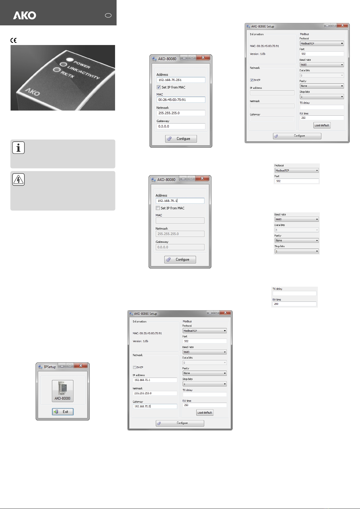
2.2.1.-Fixed IP
Configuration by temporal IP from MAC
Before setting a fixed IP or a DHCP, you have to set a temporary and
available IP in the same range that your computer in order to
configure the device. Insert the IP in the address field, check the
checkbox set IP from MAC and, enter the MAC address shown on
the permanent side label attached to the device, the format of which
is 00:26:45:XX:XX:XX. Do the same with the Netmask and the
Gateway if necessary, and press Configuration
If you know the IP assigned by the router write it in the address field
and press configuration button.
2.2.-
You have to choose between: Fixed IP or IP by DHCP.
Insert the fixed IP in the IP address field, do the same with the
Netmask and the Gateway
Configuration
Instructions
GB
8008H002 Ed.03
358008002 REV.02 2016
AKO-80080
AKO ELECTROMECÁNICA , S.A.L.
Avda. Roquetes, 30-38
08812 • Sant Pere de Ribes.
Barcelona • Spain.
Tel.: +34 902 333 145
Fax: +34 938 934 054
www.ako.com
We reserve the right to supply materials that might vary slightly to those described
in our Technical Sheets. Updated information is available on our website.
Warnings
This document provides the instructions for use
and describes the operation of the AKO-80080
device. If misplaced, the manual may be
downloaded from the AKO web site:
www.ako.com
Disconnect the device from the power supply
source before undertaking any maintenance,
modification of connections, repairs, etc. If you
suspect an operational fault in the unit or in its
protection system, remove the unit from service.
The design of the unit makes it easy to replace in
the event of a fault.
1.-Description
The AKO-80080 device is a serial physical environment to
Ethernet communications converter that uses TCP/IP
communication packages.
Please connect the device to the Ethernet network to setup it
properly.
2.-Communication
2.1.-Ethernet addressing
As the unit is connected to the master communication system
by means of an IP connection, the addressing parameters
must be configured. The configuration modes include the
assignmen
To configure the IP address configuration in any of the
available formats, run the IPSetup.exe executable supplied
with the unit.
Run IPSetup and select the AKO-80080 converter.
The device comes with DHCP activated as default parameter.
(If you know the IP you can skip the next step and go directly
to 2.1.3 Configuration by IP).
t of a fixed IP or configuration of a DHCP name. We
recommend the use of a fixed IP.
We recommend using a fixed IP address, as this will be used
by AKOnet to retrieve the data
2.1.1.-Ethernet address assignment
2.2.2.-
2.2.3.-Choose Protocol and Port
2.2.4.-Other Fields
2.2.5.-Tx Delay Rx Time
2.2.6.-Save changes
IP by DHCP
Check the DHCP checkbox and leave the other fields in blank.
Set always ModbusTCP as protocol and 502 as port.
When you choose the Modbus Tcp the other fields get
automatically the right values: 9600, 8,None & 1, as you can
see in the picture.
Set always TX delay in blank and RX as 250.
ŸTx Delay: additional delay of the RS serial bus
ŸRx Time: maximum bus waiting time
Once any change has been made to the aforementioned
sections, the information must be saved using the
“Configure” button.

3.- Technical features
4.- Connections
Power circuit
Mechanical features
Network interface
Serial interface
Single-phase
Earth connection terminal. . . . . . . . . . . . . . . . . . . . . . . . . . . . . . . . . . . . . . . . . . . . .
Frequency . . . . . . . . . . . . . . . . . . . . . . . . . . . . . . . . . . . . . . . . . . . . . . . . . . . . . 47 - 63 Hz
Maximum consumption . . . . . . . . . . . . . . . . . . . . . . . . . . . . . . . . . . . . . . . . . . . . . . . 9 VA
Working temperature . . . . . . . . . . . . . . . . . . . . . . . . . . . . . . . . . . . . . . . . . . . . -10 - 60 ºC
Humidity (no condensation) . . . . . . . . . . . . . . . . . . . . . . . . . . . . . . . . . . . . . . . . . 5 - 95 %
Case material . . . . . . . . . . . . . . . . . . . . . . . . . . . . . . . . UL94 - V0 self-extinguishing plastic
Unit protection degree . . . . . . . . . . . . . . . . . . . . . . . . . . . . . . . . . . . . . . . . . . . . . . . . IP20
Dimensions (mm) . . . . . . . . . . . . . . . . . . . . . . . . . . . . . . 35,4 x 73 x 84,68 mm (2 modules)
Weight . . . . . . . . . . . . . . . . . . . . . . . . . . . . . . . . . . . . . . . . . . . . . . . . . . . . . . . . . . 120 g
Maximum operating height . . . . . . . . . . . . . . . . . . . . . . . . . . . . . . . . . . . . . . . . . . 2000 m
Type . . . . . . . . . . . . . . . . . . . . . . . . . . . . . . . Ethernet 10BaseT / 100BaseTX self-detecting
Connector. . . . . . . . . . . . . . . . . . . . . . . . . . . . . . . . . . . . . . . . . . . . . . . . . . . . . . . . . RJ45
Network Protocols - Accesses . . . . . . . . . . . . . . . . . . . . . . . TCP / UDP / Modbus/TCP - HTTP
Type . . . . . . . . . . . . . . . . . . . . . . . . . . . . RS-485 three-wires (A+ /S GND /B-) (RX/GND/TX)
Transmission speed (configurable) . . . . . . . . 1.2, 2.4, 4.8, 9.6,19.200, 34.8, 57.6, 115.2 bps
Data bits . . . . . . . . . . . . . . . . . . . . . . . . . . . . . . . . . . . . . . . . . . . . . . . . . . . . . . . . . . . 7, 8
Parity . . . . . . . . . . . . . . . . . . . . . . . . . . . . . . . . . . . . . . . . . . . . . . . . . No parity, odd, even
Stop bit . . . . . . . . . . . . . . . . . . . . . . . . . . . . . . . . . . . . . . . . . . . . . . . . . . . . . . . . . . 1 or 2
(A1 – A2). . . . . . . . . . . . . . . . . . . . . . . . . . . . . . . . . . . . . . . . . . 196 - 253 V~
Borne
LED symbols
Standards
Safety
Flashing power LED Powered unit and CPU activity
Flashing RX/TX. . . . . . . . . . . . . . . . . . . . . . . . . RS-485 frame delivery and reception activity
LINK/ACTIVITY . . . . . . . . . . . . . . . . . . . . . . . . . . . . . . Flashing: Activity in the Ethernet bus
. . . . . . . . . . . . . . . . . . . . . . . . . . . . . . . . . . . . . . . . . . . . . . . . Green: Speed 10/100 Mb/s
IEC 60664, VDE 0110, UL 94, EN61010-1, EN55011, EN 61000-4-2, EN 61000-
4-3, 61000-4-11, EN 61000-6-4, EN 61000-6-2, EN 61000-6-1, EN 61000-6-3,
EN 61000-4-5, CE
Installation category: Category III / EN61010 double-insulated electric shock
protection class II. The unit must be connected to a power circuit protected with
type gl fuses, in compliance with IEC 269, or type M, with values from 0.5 to 1A.
It must be fitted with a circuit breaker switch or equivalent device in order to be
able to disconnect the unit from the power supply. The power supply cable must
2
have a minimum cross-section of 1 mm .
If the unit is not operated according to the manufacturer's specifications, its
guaranteed degree of protection may be compromised.
................................
KEEP THIS DATA SHEET SAFE
FOR FUTURE REFERENCE
A
A
S
S
A1
A1
B
B
A2
A2
Tr+
Tr+
GND
GND
Tr-
Tr-
AKO-80080
Converter
AKO-80080
Converter
196-253 V~
47-63 Hz
196-253 V~
47-63 Hz
ESC ?
SET
ESC ?
SET
CAMRegis
CAMCtrl
AKOControl
with communication
AKOControl
with communication
1000 m
Maximum of 25 computers
AKO-5012
LAN
AKOControl
with communication
CAMAlarm
PROPlus
Tr+
GND
Tr-
Tr+
GND
Tr-
Tr+
GND
Tr-
Tr+
GND
Tr-
Tr+
GND
Tr-
Tr+
GND
Tr-
Tr+
GND
Tr-
Ethernet
TCP/IP
Switch
The AKO-5012 web server supports up to 10 AKO-80080 converters and the AKO-5014 web server supports up to 2.
Terminating resistors are not required.
This manual suits for next models
1
Other AKO Media Converter manuals