MANTENIMIENTO:
Limpie la superficie del controlador con un paño suave, agua y jabón. No utilice detergentes abrasivos, gasolina, alcohol o
disolventes.
Los parámetros sólo deben ser programados o modificados por personal que
conozca el funcionamiento y las posibilidades del equipo donde se aplica.
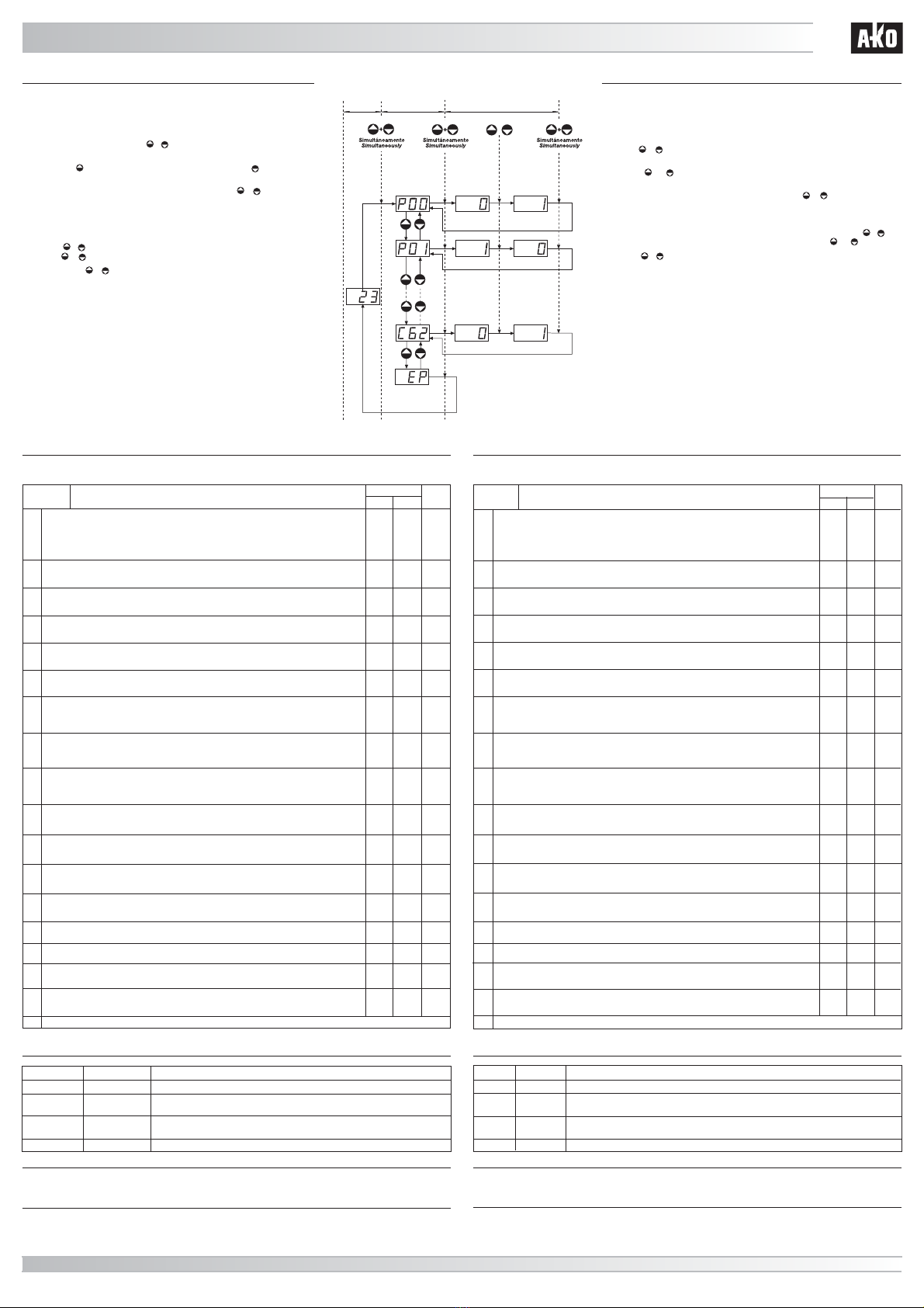
Programación de parámetros:
Nivel 1:
- Pulse simultáneamente las teclas + durante 10 segundos. El led PR se
iluminará de forma intermitente y en el display aparecerá el primer parámetro “P00”.
- Pulse la tecla para acceder al parámetro siguiente y la tecla para retroceder
al parámetro anterior.
- Situándonos en el último parámetro EP, pulsando las teclas + simultánemente,
el controlador volverá a la situación de indicación de temperatura y el led PR dejará
de iluminarse de forma intermitente.
Nivel 2:
- Para ver el valor actual de cualquier parámetro, sitúese en el que se desea y pulse
las teclas + simultáneamente. Una vez visualizado, si quiere modificarlo pulse
las teclas ó .
- Pulse las teclas + simultáneamente para fijar el nuevo valor. Al realizar esta
operación la programación volverà al nivel 1 (parámetros).
NOTA: Si no se pulsa tecla alguna durante 30 segundos en cualquiera de los pasos
anteriores, el controlador volverá automáticamente a la situación de indicación de
temperatura, sin modificar el valor de los parámetros.
Parameters should only be programmed or chenged by personnel familiar with
the operation of the apparatus and its possibilities where applied.
Programming parameters:
Level 1:
- Hold the + keys down simultaneously for 10 seconds. The PR led will flash and
the first parameter, “P00”, will be shown on the display.
- Press the or key to change to the next parameter or previous parameter,
respectively.
- When the final parameter EP is on the display, press the + keys simultaneously,
the controller will return to the temperature display and the PR led will stop flashing.
Level 2:
- To see the current value of any parameter, find the one you want and press the + keys
simultaneously. When it is on display, you can change it with the or keys.
- Press the + keys simultaneously to set the new value. When you do this, the
programming will return to level 1 (parameters).
NOTE: If no key is pressed for 30 seconds during any of these steps, the controller
automatically returns to temperature display, none of the parameter values being
changed.
351472100 REV. 05 2005 D.L.: B-3.050-2002 Nos reservamos el derecho de suministrar materiales que pudieran diferir levemente de los descritos en nuestras hojas técnicas.
www.ako.com
HOJA TÉCNICA 1472H100 Edición 06 (02 de 02)
AKO Electromecànica, S.A.L. Av. Roquetes, 30-38 08812 S. PERE DE RIBES (Barcelona)(
Spain)
El uso del equipo no respetando las instrucciones del fabricante, puede alterar los requisitos de seguridad del mismo.
VISUALIZACIÓN
ESTADO DESCRIPCIÓN
MENSAJES DE FUNCIONAMIENTO:
AH Intermitente con
la temperatura Temperatura por encima del valor de los limitadores máximos del punto de ajuste de
C21 y C22.
AL Intermitente con
la temperatura Temperatura por debajo del valor de los limitadores mínimos del punto de ajuste de
C31 y C32.
E1 Fijo Sonda en corto circuito, circuito abierto, >614ºC ó <-60.6ºC
EE Fijo Fallo de memoria.
ADVERTENCIAS:
P00 Modo de funcionamiento
Selección 0 = Actuación ON-OFF
Ver modos de funcionamiento.
Posibilidad de programar puntos de ajuste independientes para cada relé.
Selección 1 = zona neutra.
Ver modos de funcionamiento.
DESCRIPCIÓN RANGO
MIN.
0
MAX.
DEF.
10
P01 Funcionamiento (frío/calor) del relé 1
Selección 0 = Frío
Selección 1 = Calor
P02 Funcionamiento (frío/calor) del relé 2
Selección 0 = Frío
Selección 1 = Calor
011
P07 Resolución para la visualización de la temperatura
0=0,1 ºC entre –50,0 y +99,9 ºC, resto de escala 1 ºC
1 = 1 ºC en toda la escala. 010
P3 Volver a parámetros iniciales
1 = sí, configura todos los parámetros del equipo con los valores de la columna DEF de estas
instrucciones y sale inmediatamente de programación. -
C0 Calibración de la sonda (offset).
Incremento / decremento de temperatura que se añade a la temperatura detectada por el
termostato para ajustar la sonda al valor real. -20ºC 20ºC 0ºC
-650ºC +650ºC 2ºC
-650ºC +650ºC 2ºC
C11 Diferencial R1
Incremento o decremento de temperatura por encima o por debajo de la temperatura indicada por el
PUNTO DE AJUSTE 1 (SP1) para que actúe el relé 1.
Ver funcionamiento relé 1 en actuación ON-OFF.
C12 Diferencial R2
Incremento o decremento de temperatura por encima o por debajo de la temperatura indicada por el
PUNTO DE AJUSTE 2 (SP2) para que actúe el relé 2.
Ver funcionamiento relé 2 en actuación ON-OFF.
1ºC 325ºC 2ºC
C15 Valor zona neutra
Incremento y decremento de temperatura por encima o por debajo de la temperatura programada
en el PUNTO DE AJUSTE 1 (SP1) para que actúen los relés R1 y R2.
Ver funcionamiento Zona Neutra.
xxxºC 600ºC 600ºC
C21 Limitador máximo del PUNTO DE AJUSTE (Set Point) R1
No se podrá fijar un SET POINT del relé 1 por encima de este valor, apareciendo la indicación de
alarma AH si la temperatura es superior al valor de C21 y C22.
xxxºC 600ºC 600ºC
C22 Limitador máximo del PUNTO DE AJUSTE (Set Point) R2
No se podrá fijar un SET POINT del relé 2 por encima de este valor, apareciendo la indicación de
alarma AH si la temperatura es superior al valor de C21 y C22.
-50ºC xxxºC -50ºC
C31 Limitador mínimo del PUNTO DE AJUSTE (Set Point) R1
No se podrá fijar un SET POINT del relé 1 por debajo de este valor, apareciendo la indicación de
alarma AL si la temperatura es inferior al valor de C31 y C32.
-50ºC xxxºC -50ºC
C32 Limitador mínimo del PUNTO DE AJUSTE (Set Point) R2
No se podrá fijar un SET POINT del relé 2 por debajo de este valor, apareciendo la indicación de
alarma AL si la temperatura es inferior al valor de C31 y C32.
0 min. 99 min. 0 min.
C51 Retardo accionamiento relé R1
Retardo a la conexión del relé 1 desde que la temperatura manda activarlo.
0 min. 99 min. 0 min.
C52 Retardo accionamiento relé R2
Retardo a la conexión del relé 2 desde que la temperatura manda activarlo.
010
C61 Estado de R1 con sonda averiada
0 = off
1 = on
010
C62
EP
Estado de R2 con sonda averiada
0 = off
1 = on
Salida de programación
011
1-
VALOR
Para programar los PUNTOS DE AJUSTE (Set Point) ver AJUSTES DE LA TEMPERATURA.
Los valores de la columna DEF. vienen programados de fábrica.
DESCRIPCIÓN DE LOS PARÁMETROS:
PROGRAMACIÓN:
INDICACIÓN
TEMPERATURA
TEMPERATURE
INDICATION
NIVEL 2
VALORES
LEVEL 2 VALUES
NIVEL 1
PARÁMETROS
LEVEL 1 PARAMETERS
VISUALIZAR
VALOR
DISPLAY VALUES
VARIAR VALOR
CHANGE VALUES
ACEPTAR EL
NUEVO
ENTER NEW
VALUES
VALOR ACTUAL
CURRENT VALUE
NUEVO VALOR
NEW VALUE
10 Seg./ 10 Sec.
SALIDA PROGRAMACIÓN
PROGRAMMING EXIT
PROGRAMMING:
Using this unit without heeding the manufacturer’s instructions may change its safety requirements.
DISPLAY STATE DESCRIPTION
OPERATING MESSAGES:
AH Flashing with
temperature
Temperature above the maximum limit values set in C21 and C22.
AL Flashing with
temperature
Temperature below the minimum limit values set in C31 and C32.
E1 Steady Probe short circuited, circuit open >614ºC or <-60.6ºC
EE Steady Memory failure
MAINTENANCE:
WARNINGS:
Clean the surface of the controller with a smooth cloth, soap and water. Do not use abrasive detergents, petrol, alcohol or
solvents.
P00 Operating mode
Selection 0= ON-OFF Switching.
See operating modes.
Set points can be programmed separately for each relay.
Selection 1 = neutral zone.
See operating modes.
DESCRIPTION RANGE
MIN.
0
MAX. VALUE
10
P01 Operation (cold/heat) of relay 1
Selection 0 = Cold
Selection 1 = Heat
P02 Operation (cold/heat) of relay 2
Selection 0 = Cold
Selection 1 = Heat
011
011
DEF.
For Set Point programming, see TEMPERATURE SET POINT.
The figures in the DEF column are the factory settings.
DESCRIPTION OF PARAMETERS:
P07 Resolution for temperature display.
0=0,1ºC between -50,0 and +99,9ºC rest of the range 1ºC
1= 1ºC for the complete range.
010
P3 Return to original parameters
1 sets all parameters in the device to the values in the DEF. VALUE column of this table, then
exits programming immediately.
-
C0 Probe calibration (offset)
Increases or decreases the correction to the temperature detected by the thermostat in order to
adjust the probe to real temperature.
-20ºC 20ºC 0ºC
-650ºC +650ºC 2ºC
-650ºC +650ºC 2ºC
C11 R1 Differential
Increases or decreases the temperature from that indicated by SET POINT 1 (SP1) for R1 to be
switched on.
See relay 1 operating in ON-OFF switching mode.
C12 R2 Differential
Increase or decreases the temperature from that indicated by SET POINT 2 (SP2) for R2 to be
switched on.
See relay 2 operating in ON-OFF switching mode.
1ºC 325ºC 2ºC
C15 Neutral zone value
Increases/decreases the temperature above or below SET POINT 1 for relays R1 and R2 to
act.
See Neutral Zone operating.
xxxºC 600ºC 600ºC
C22 Maximum limit for R2 SET POINT
Relay 2’s SET POINT cannot be established above this figure, the alarm AH being produced if the
temperature is above the value of C21 and C22.
-50ºC xxxºC -50ºC
C31 Minimum limit for R1 SET POINT
Relay 1’s SET POINT cannot be established below this figure, the alarm AL being produced if the
temperature is less than the value of C31 and C32.
-50ºC xxxºC -50ºC
C32 Minimum limit for R2 SET POINT
Relay 2’s SET POINT cannot be established below this figure, the alarm AL being produced if the
temperature is less than the value of C31 and C32.
0 min. 99 min. 0 min.
C51 Relay R1 Triggering Delay
Delay for R1 being triggered after the temperature commands its activation.
0 min. 99 min. 0 min.
C52 Relay R2 Triggering Delay
Delay for R2 being triggered after the temperature commands its activation.
010
C61 R1 status when the probe has failed
0=off
1=on
010
C62
EP
R2 status when the probe has failed
0=off
1=on
Exit Programming
1-
xxxºC 600ºC 600ºC
C21 Maximum limit for R1 SET POINT
Relay 1’s SET POINT cannot be established above this figure, the alarm AH being produced if the
temperature is above the value of C21 and C22.
PARÁMETRO PARAMETER


