manuals.online logo
Brands
  1. Home
  2. •
  3. Brands
  4. •
  5. AKO
  6. •
  7. Thermostat
  8. •
  9. AKO AKO-14712 User manual

AKO AKO-14712 User manual

230 V⬃,±10% 7.8 mA ⬃
12 V ⬃, ±20% 96 mA ⬃
AKO-14716 For panel 8A,cos  =1(SPDT)
AKO-14712 For panel 8A,cos  =1(SPDT)
AKO-14716 Panelable 8A,cos  =1(SPDT) 230 V ⬃, ±10% 7.8 mA ⬃
AKO-14712 Panelable 8A,cos  =1(SPDT) 12 V ⬃, ±20% 96 mA ⬃
INSTALACIÓN:
Termostato:
El termostato debe ser instalado en un sitio protegido de las vibraciones, del agua y de los gases corrosivos, y donde la
temperatura ambiente no supere los valores reflejados en los datos técnicos.
Para que el equipo tenga un grado de protección IP65 deberá instalarse correctamente la junta entre el aparato y el perí-
metro del hueco del panel donde deba montarse.
Sonda:
Para que la lectura sea correcta, la sonda se ha de instalar en un sitio sin influencias térmicas ajenas a la temperatura que
se desea medir o controlar.
Conexionado:
Ver esquema en la etiqueta de características de los aparatos.
Los cables para el conexionado de los contactos de los relés deberan tener una
sección de entre 1 mm2y 2,5 mm2.
La sonda y su cable correspondiente NUNCA deben instalarse en una con-
ducción junto con cables de potencia, control o alimentación.
El circuito de alimentación debe estar provisto de un interruptor para su des-
conexión de mínimo 2A, 230V, situado cerca del aparato. Los cables entrarán
por la parte posterior y serán del tipo H05VV-F 2x0.5 mm2o H05V-K 1x0.5mm2.
Anclaje:
Para la fijación del aparato situar los anclajes 1sobre las guias 2en la posición
de la figura. Desplazar el anclaje en el sentido de la flecha. Presionando la pes-
taña 3puede desplazarse el anclaje en sentido contrario a la flecha.
INSTALLATION:
Thermostat:
The thermostat must be installed in a place protected from vibrations, water and corrosive gases, and where the ambient
temperature does not surpass the values specified in the technical data.
For the equipment for panel to be suitable having IP65 protection the gasket should be installed properly between the appa-
ratus and the perimeter of the panel cut-out where it is to be fitted.
Probe:
To give a correct reading, the probe has to be installed in a place without heat influences other than the temperature that is
to be measured or controlled.
Connection:
See diagram in the unit rating plate.
Section of connecting wires for relays contacts must be between 1 mm2and 2,5 mm2.
The probe and its lead should NEVER be installed in a conduct next to power,
control or power supply wiring systems.
The power supply circuit should be connected with a switch for disconnection of
minimum 2A, 230V, located near the unit. The connection cables should be
H05VV-F 2x0,5mm2or H05V-K 1x0,5mm2type, to posterior part of the unit.
Fastening of models for panel:
To fix the unit, place the fasteners 1via the sliders 2as shown in the figure. Move
the fasteners in the direction of the arrow. Press tab 3to move the fasteners in the
opposite direction of the arrow.
-Pulse la tecla durante 5 segundos. Se visualizará el valor del AJUSTE (Set
Point) actual y se iluminará el LED PR de forma intermitente.
-Pulse las teclas ó para seleccionar el AJUSTE (Set Point) al valor dese-
ado.
-Pulse las teclas + simultáneamente para fijar el nuevo valor. Al realizar
esta operación, el display volverá a la situación de indicación de temperatu-
ra y el LED PR dejará de iluminarse de forma intermitente.
NOTA: Si no se pulsa tecla alguna durante 30 segundos en cualquiera de los
pasos anteriores, el controlador volverá automáticamente a la situación de
indicación de temperatura, sin modificar el valor del AJUSTE (Set Point).
Funciones:
En programación, sube el valor que se está visualizando.
Pulsando durante 5 segundos se visualiza la temperatura del PUNTO
DE AJUSTE (Set Point).
En programación, baja el valor que se está visualizando.
Pulsanso simultáneamente durante 10 segundos se entra en el menú
de programación.
Pulsando simultáneamente se fija el nuevo valor.
LEDS indicadores:
LED PR permanente: Fase de programación de parámetros.
LED PR intermitente: Fase de programación del PUNTO DE AJUSTE (Set Point).
LED 1 permanente: Relé activado (ON).
LED 1 intermitente: Por temperatura detectada en la sonda debería estar
activado el relé, pero no lo está debido algún parámetro
programado.
www.ako.es
HOJA TÉCNICA 1471H200 Edición 03 (01 de 02)
ETermostatos digitales hasta 150ºC
con 1 sonda PTC y 1 relé SPDT:
AKO-14712, AKO-14716
GB Digital thermostats up to 150°C
for 1 PTC probe and 1 SPDT relay:
AKO-14712, AKO-14716
DESCRIPCIÓN GENERAL:
Termostatos electrónicos panelables, adecuados para visualizar, controlar y regular generadores de frío o de calor.
DATOS TÉCNICOS:
Rango de temperatura: ........................................................................................................................................-50ºC a 150ºC
Entrada sonda PTC: ........................................................................................................................................Ref. AKO-1558X
Precisión del controlador:....................................................................................................................................................±1ºC
Tolerancia de la sonda a 25ºC: ......................................................................................................................................±1.25ºC
Temp. ambiente de trabajo: ......................................................................................................................................5ºC a 50ºC
Temp. ambiente de almacenaje: ............................................................................................................................-30ºC a 70ºC
VERSIONES:
-de montaje independiente
-de característica de funcionamiento automático Acción Tipo 1.B
-para utilización en situación limpia
-soporte lógico (software) clase A
Clasificación dispositivo de control:
máx.
18 mm 32
1
61,5 70,5
28,5
HUECO PANEL
PANEL CUT-OUT
44
LED PR
PR
LED 1 1
TECLA SUBIR
UP KEY
TECLA BAJAR
DOWN KEY
2
FUNCIONES DEL FRONTAL
+
+
AJUSTE DE LA TEMPERATURA:
El valor de fábrica, de AJUSTE DE TEMPERATURA (Set Point) por defecto es
de 0°C.
5 seg.
5 Sec
.
AJUSTE
ACTUAL
CURRENT
SET POINT
INDICACIÓN
TEMPERATURA
CURRENT
TEMPERATURE
NUEVO
AJUSTE
NEW
SET POINT
ACEPTAR EL
NUEVO
ACCEPT
THE NEW
VARIAR AJUSTE
CHANGE
SET POINT
VISUALIZAR
AJUSTE
DISPLAY
SET POINT
FRÍO
COLD
CALOR
HEAT
RELÉ ON
RELAY ON RELÉ ON
RELAY ON
Diferencial
Differential Diferencial
Differential
RELÉ OFF
RELAY OFF RELÉ OFF
RELAY OFF
-T +T
PUNTO DE AJUSTE
SET POINT PUNTO DE AJUSTE
SET POINT
GENERAL DESCRIPTION:
Electronic thermostats (for panel and for surface), suitable for displaying, controlling and adjusting cold or heat generators..
VERSIONS:
MODEL FASTENING RELAY POWER SUPPLY, 50/60 Hz
-with independent mounting
-with characteristic of automatic operation action, Type 1.B
-to be used in clean situation
-logical medium (software) class A
Control device classification:
FRONT PANEL FUNCTIONS:
In programming, it increases the displayed value.
Press for 5 seconds to displays the Set Point temperature.
In programming it reduces the displayed value.
Held down simultaneously for 10 seconds brings up the programming
menu.
Held down simultaneously enters the new value.
+
+
Indicator LEDS:
LED PR constant: Parameters programming phase.
LED PR flashing: SET POINT programming phase.
LED 1 constant : Shows relay is ON.
LED 1 flashing : Means relay should be ON according to the temperature detected by the probe, but is not, owing to a
programming condition.
Functions:
TEMPERATURE ADJUSTMENT:
The factory SET POINT value for temperature is 0ºC.
-Press the key for 5 seconds. The current SET POINT value will be displayed
and LED PR will flash.
-Press the or keys to adjust the SET POINT to the required value.
-Press the + keys simultaneously to set the new value. The display will
revert to temperature indication status and the LED PR stop flashing.
NOTE: If no key is pressed for 30 seconds in either of the previous steps the con-
troller will automatically revert to the temperature indication status without
modifying the SET POINT value.
MODELO ANCLAJE RELÉ ALIMENTACIÓN, 50/60 Hz
TECHNICAL DATA:
Temperature range: ..............................................................................................................................................-50ºC to 150ºC
PTC probe input: ..............................................................................................................................................Ref. AKO-1558X
Controller accuracy:..............................................................................................................................................................±1ºC
Probe tolerance at 25 °C: ................................................................................................................................................±1.25ºC
Working ambient temperature: ..................................................................................................................................5ºC to 50ºC
Storage ambient temperature:................................................................................................................................-30ºC to 70ºC
351471200 REV. 02 2002 D.L.: B-3.051-2002 Nos reservamos el derecho de suministrar materiales que pudieran diferir levemente de los descritos en nuestras hojas técnicas.
www.ako.es
HOJA TÉCNICA 1471H200 Edición 03 (02 de 02)
AKO Electromecànica, S.A.L. Av. Roquetes, 30-38 08812 S. PERE DE RIBES (Barcelona)(
Spain)
Los parámetros sólo deben ser programados o modificados por per-
sonal que conozca el funcionamiento y las posibilidades del equipo
donde se aplica.
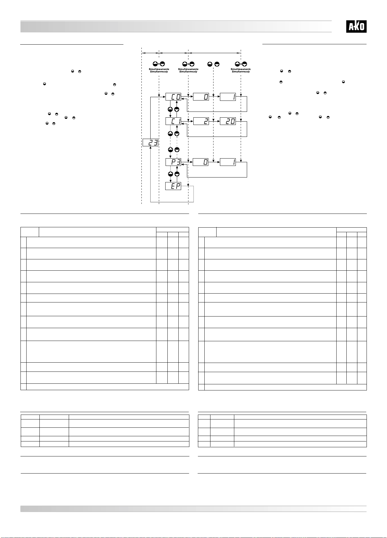
Programación de parámetros:
Nivel 1:
- Pulse simultáneamente las teclas + durante 10 segundos. El LED
PR se iluminará de forma permanente y en el display aparecerá el primer
parámetro “C0”.
- Pulse la tecla para acceder al parámetro siguiente y la tecla para
retroceder al parámetro anterior.
-Situándonos en el último parámetro EP, pulsando las teclas + simul-
táneamente, el controlador volverá a la situación de indicación de tempe-
ratura y el LED PR dejará de iluminarse de forma permanente.
Nivel 2:
-Para ver el valor actual de cualquier parámetro, sitúese en el que se desea
y pulse las teclas + simultáneamente. Una vez visualizado, si quie-
re modificarlo pulse las teclas ó .
- Pulse las teclas + simultáneamente para fijar el nuevo valor. Al rea-
lizar esta operación la programación volverá al nivel 1 (parámetros).
NOTA: Si no se pulsa tecla alguna durante 30 segundos en cualquiera de
los pasos anteriores, el controlador volverá automáticamente a la situación
de indicación de tempereatura, sin modificar el valor de los parámetros.
PROGRAMACIÓN:
INDICACIÓN
TEMPERATURA
TEMPERATURE
DISPLAY
NIVEL 2
VALORES
LEVEL 2
VALUES
NIVEL 1
PARÁMETROS
LEVEL 1
PARAMETERS
VISUALIZAR
VALOR
DISPLAY VALUE
ACEPTAR EL
NUEVO
ACCEPT
THE NEW
VARIAR VALOR
CHANGE VALUE
VALOR ACTUAL
CURRENT VALUE
NUEVO VALOR
NEW VALUE
10 Seg./ 10 Sec.
SALIDA
PROGRAMACIÓN
EXIT PROGRAMMING
C2 Limitador máximo del PUNTO DE AJUSTE (Set point)
No se podrá fijar un SET POINT por encima de este valor, apareciendo la indicación de alarma AH si la
temperatura es superior a C2. xxºC 150ºC 150ºC
C3 Limitador mínimo del PUNTO DE AJUSTE (Set point)
No se podrá fijar un SET POINT por debajo de este valor, apareciendo la indicación de alarma AL si la
temperatura es inferior a C3. -50ºC xxºC
-50ºC
C4 Tipo de retardo para protección de arranque
0 = (off/on): Retardo a la conexión del relé desde su última desactivación.
1 = (on): Retardo a la conexión del relé desde que la temperatura manda activarlo.
C5 Tiempo de retardo de la protección
Valor numérico de la opción elegida en el parámetro C4. 0 min. 99 min.
0 min.
C6 Estado del relé con sonda averiada
0 = off
1 = on
2 = Secuéncia de funcionamiento (OFF/ON), según lo programado en C7 y C8. 0
C7 Tiempo relé conectado (ON) en caso de fallo de la sonda
Periodo en que el controlador permanece con el relé conectado (Ej. marcha compresor).
Programando C7 = 0 et C8 ≠0, el relé estará siempre desconectado (OFF). 0 min. 99 min.
10 min.
C8 Tiempo relé desconectado (OFF) en caso de fallo de sonda
Periodo en que el controlador permanece con el relé desconectado (Ej. paro compresor).
Programando C8 = 0 et C7 ≠0, el relé estará siempre conectado (ON). 0 min. 99 min.
5 min.
P0 Tipo de funcionamiento (frío/calor)
Selección del funcionamiento del termostato para aplicaciones del frío o del calor.
Selección 0 = Frío
Diferencial por encima del PUNTO DE AJUSTE (Set point).
Selección 1 = Calor
Diferencial por debajo del PUNTO DE AJUSTE (Set point).
011
P1 Retardo de todas las funciones
Retardo de todas las funciones cuando el aparato recibe alimentación eléctrica. 0 min. 0 min. 99 min.
P3 Volver a los parámetros iniciales
1 = sí, configura todos los parámetros del equipo con los valores de la columna DEF de estas ins-
trucciones y sale inmediatamente de programación. —
NOTA: Cuando se modifican los parámetros de tiempo, los nuevos valores, los aplicará una vez finalizado el ciclo que esta-
ba realizando. Para que lo haga inmediatamente, desconectar y volver a conectar el controlador.
Salida de programación
EP
MANTENIMIENTO:
Limpie la superficie del controlador con un paño suave, agua y jabón. No utilice detergentes abrasivos, gasolina, alcohol
o disolventes.
ADVERTENCIAS:
El uso del equipo no respetando las instrucciones del fabricante, puede alterar los requisitos de seguridad del mismo.
Para el funcionamiento correcto del aparato solamente deberán utilizarse sondas del tipo PTC de las suministradas por
AKO.
Entre 0ºC y 150ºC, si se prolonga la sondacon cable de mínimo 0,5 mm2y hasta 100m la desviación será de 1ºC.
MENSAJES DE FUNCIONAMIENTO:
DESCRIPCIÓN
ESTADO
VISUALIZACIÓN
001
2
0
—1
Intermitente con la
temperatura
Intermitente con la
temperatura
Fijo
Fijo
EE
E1
AL
AH Temperatura por encima del valor del limitador máximo del Punto de Ajuste de C2 o bien
entre 150ºC < temp. < 159ºC.
Temperatura por debajo del valor del limitador mínimo del Punto de Ajuste de C3 o bien
entre - 55ºC < temp. < - 50ºC.
Sonda en cortocircuito, circuito abierto, > 160ºC ou < - 55ºC.
Fallo de memoria
DESCRIPCIÓN DE LOS PARÁMETROS:
PARÁMETRO
C0 Calibración de la sonda (Offset)
Incremento / Decremento de temperatura que se añade a la temperatura detectada por el termostato
para ajustar la sonda al valor real.
DESCRIPCIÓN MIN.
–20ºC
Para programar el PUNTO DE AJUSTE (Set Point) ver AJUSTE DE LA TEMPERATURA.
Los valores de la columna DEF. vienen programados de fábrica.
MAX.
DEF.
+20ºC
0ºC
C1 Diferencial (Hystéresis).
Incremento de temperatura por encima o por debajo de la temperatura indicada por el PUNTO DE
AJUSTE (Set Point) para que actúe el relé. 1ºC 20ºC
2ºC
VALOR
The parameters may only be programmed or modified by staff that are
fully acquainted with how the machine operates and the characteristics
of the unit where it is to be applied.
Programming parameters:
Level 1:
- Press the + keys simultaneously for 10 seconds. LED PR will light
and the first parameter “C0” will appear on the display.
- Press the key to access the next parameter and the key to go back
to the previous one.
- In the last parameter, EPpressing the + keys simultaneously the con-
troller will revert to temperature indication status and the LED PR stop ligh-
ting.
Level 2:
- To display the current value of any parameter, go to the required parame-
ter and press the + keys simultaneously. Once it is on screen, press
the or keys to modify it.Press the + keys simultaneously to set
the new value. The programming will revert to level 1 (parameters).
NOTE: If no key is pressed for 30 seconds in either of the previous steps the
controller will automatically revert to the temperature indication status
without modifying the parameter value.
PROGRAMMING:
C2 Maximum SET POINT limiter
The SET POINT cannot be set above this value, with the AH temperature alarm activated if the tempera-
ture is above C2. xxºC 150ºC 150ºC
C3 Minimum SET POINT limiter
The SET POINT cannot be set below this value, with the AL temperature alarm activated if the tempera-
ture is below C3. -50ºC xxºC
-50ºC
C4 Type of delay for starting
0=(off/on): Delays relay connection as of last deactivation.
1=(on): Delays relay connection once the temperature has it activated. 001
C5 Protection delay time
Number value of the option selected in parameter C4
99 min.
0 min.
0 min.
C7 Time relay is ON in case of probe failure
Period for which the controller relay stays ON, (e.g. compressor on).
With C7=0 and C8≠0 programmed, the relay will always be OFF. 0 min.
99 min.
10 min.
C8 Time relay is OFF in case of probe failure
Period for which the controller relay stays OFF (e.g. compressor off).
With C8=0 and C7≠0 programmed, the relay will always be ON. 0 min.
99 min.
5 min.
P0 Type of operation (cold/heat)
Selects thermostat operation for cold or heat applications
Selection 0=Cold
Differential above the SET POINT
Selection 1=Heat
Differential below the SET POINT
011
P1 Delay all functions
Delays all functions when the apparatus is powered up. 0 min.
99 min.
0 min
P3 Revert to initial parameters
1=yes, configures all the parameters of the unit with the values of the DEF column of these instructions
and exit from programming. —1
—
NOTE: When time parameters are modified, the new values will be applied once the cycle in progress has concluded. If you
wish it to be done immediately, switch the controller off and on again.
Exit programming
EP
MAINTENANCE:
Clean the surface of the controller with a soft cloth and soap and water. Do not use abrasive detergents, petrol, alcohol or
solvents.
WARNINGS:
The use of the unit different to the manufacturer’s instructions voids the safety qualification.
Use only PTC type AKO supplied probes for the device to work properly.
Between 0ºC and 150ºC, when probe is extended with minimum 0.5 mm2up to 100m cable, deviation will be of 1ºC.
OPERATING MESSAGES:
C6 Relay status in case of probe failure
0=off
1=on
2=Operating sequence (OFF/ON) as programmed in C7 and C8.
0 2
0
DESCRIPTION
DISPLAY
STATE
E1
EE
Flashing with
temperature
Flashing with
temperature
Steady
Steady
Temperature above the maximum limiter values set in C2 or else between 150°C < temp. < 159°C.
Temperature below the minium limiter values set in C3 or else between -55°C < temp. < -50°C.
Probe short circuited, circuit open, > 160°C or < -55°C
Memory failure
AH
AL
DESCRIPTION OF THE PARAMETERS:
PARAMETER
DESCRIPTION MIN.
See TEMPERATURE ADJUSTMENT (Set Point) for programming it.
The values of the DEF column are factory-set.
MAX.
DEF.
C1 Differential (Hysteresis)
Temperature increase above or below the temperature indicated by the SET POINT for operation relay. 1ºC 20ºC
2ºC
VALUE
C0 Probe calibration (Offset)
Temperature Increase / Decrease added to the temperature detected by the thermostat to adjust the
probe to the real value. –20ºC +20ºC
0ºC

This manual suits for next models

1

Other AKO Thermostat manuals

AKO AKO-D14120 User manual

AKO

AKO AKO-D14120 User manual

AKO AKO-D1461 Series User manual

AKO

AKO AKO-D1461 Series User manual

AKO 1530 User manual

AKO

AKO 1530 User manual

AKO 14721 User manual

AKO

AKO 14721 User manual

AKO 14723 User manual

AKO

AKO 14723 User manual

AKO 226.0120 Series User guide

AKO

AKO 226.0120 Series User guide

AKO AKO-15646 User manual

AKO

AKO AKO-15646 User manual

Popular Thermostat manuals by other brands

Lennox ComfortSense L7742U owner's manual

Lennox

Lennox ComfortSense L7742U owner's manual

White Rodgers 1F84-51 Installation and operation instructions

White Rodgers

White Rodgers 1F84-51 Installation and operation instructions

DELTA DORE TYBOX 51 manual

DELTA DORE

DELTA DORE TYBOX 51 manual

Honeywell RTH8500WF quick start guide

Honeywell

Honeywell RTH8500WF quick start guide

Zehnder Rittling ComfoControl Ease Installer manual

Zehnder Rittling

Zehnder Rittling ComfoControl Ease Installer manual

LSB ATA11U03 User operating instructions

LSB

LSB ATA11U03 User operating instructions

PALLADIOM QS Room Thermostat Configuration instructions

PALLADIOM

PALLADIOM QS Room Thermostat Configuration instructions

Fri-Jado FK400T instructions

Fri-Jado

Fri-Jado FK400T instructions

Siemens RDG400KN manual

Siemens

Siemens RDG400KN manual

Neomitis RTANEOA Installation and operating instructions

Neomitis

Neomitis RTANEOA Installation and operating instructions

Specified Controls SC-T32-TS installation manual

Specified Controls

Specified Controls SC-T32-TS installation manual

EcoNet UETST800SYS user guide

EcoNet

EcoNet UETST800SYS user guide

Honeywell Lyric installation guide

Honeywell

Honeywell Lyric installation guide

Gabarron TA3 Installation instructions and user guide

Gabarron

Gabarron TA3 Installation instructions and user guide

DOTECH TX3H-00 operating instructions

DOTECH

DOTECH TX3H-00 operating instructions

White Rodgers 90 SERIES 1F95-391 operating instructions

White Rodgers

White Rodgers 90 SERIES 1F95-391 operating instructions

Heatmiser DS-SB installation manual

Heatmiser

Heatmiser DS-SB installation manual

Daikin EKRTWA Operation manual

Daikin

Daikin EKRTWA Operation manual

manuals.online logo
manuals.online logoBrands
  • About & Mission
  • Contact us
  • Privacy Policy
  • Terms and Conditions

Copyright 2025 Manuals.Online. All Rights Reserved.