Akron SABERMASTER 1577 Assembly instructions

The following is intended to provide the basic instructions for installation, operating and maintenance of the
Electric Ladder Pipe & SaberMaster Nozzle.
TOOLS REQUIRED FOR INSTALLATION OF ELECTRIC LADDER PIPE
• Utility knife • Medium flat screwdriver
• Medium Phillips screwdriver • Small flat screwdriver
• Small Phillips screwdriver • 1⁄2inch hex head wrench
• Electrician’s pliers (multipurpose, • 3⁄16 Allen Wrench
stripping and crimping)
PRODUCT RATINGS FOR ELECTRIC LADDER PIPE
Maximum motor current draw:
12 volt versions 14.0 amps for elevation motor
3.0 amps for nozzle pattern motor
24 volt versions 7.5 amps for elevation motor
1.5 amps for nozzle pattern motor
Normal operating current (depending on operating conditions—pressure, flow, etc.):
12 volt versions 3 - 10 amps for elevation motor
0.7 amps for nozzle pattern motor
24 volt versions 2 - 5 amps for elevation motor
0.4 amps for nozzle pattern motor
Minimum Voltage:
All 12 volt motors: 11.5 volts
All 24 volt motors: 23 volts
Mass: 30 lbs. (13.6 kg)
Maximum Flow: 1000 GPM
Maximum Pressure: 200 PSI
Noise Emission: 93 Db @ 1m with maximum flow
117299 & 119210
STYLE 1494 ELECTRIC LADDER PIPE
& STYLE 1577 SABERMASTER™ NOZZLE
INSTALLATION, OPERATING AND MAINTENANCE INSTRUCTIONS
( Versions Available)

PRODUCT RATINGS FOR SABERMASTER NOZZLE
Standard Flow: Fog 1250 gpm at 80 psi
2" Smooth Bore - 840 gpm at 50 psi, 1188 gpm at 80 psi
Optional Flow: Fog 1000 gpm at 80 psi
1 15/1 " Smooth Bore - 789 gpm at 50 psi, 998 gpm at 80 psi
Maximum Pressure: 200 psi/14 bar
Minimum Voltage at motor: 12 Volt Motor: 10 Volts at 15 amps
24 Volt Motor: 20 Volts at 7.5 amps
Maximum Motor Current Draw: 10 amps
Normal Operating Current Draw: 5 amps
PRODUCT WARNINGS FOR ELECTRIC LADDER PIPE
WARNING: Aim the Electric Ladder Pipe in a safe direction before pumping water through it.
WARNING: Ensure the ladder being used has adequate structural strength to support the reaction force
generated during operation.
WARNING: Although the logic box includes a water resistant coating it is important to keep water out of
the controllers and logic box. Prolonged exposure to water will cause damage. When the
cover of the controllers or logic box is removed, check that the O-Ring under the cover is
intact and free of dirt and debris.
WARNING: The Electric Ladder Pipe uses current limiting for both the monitor and nozzle stops. Use
only appropriate Akron Brass®nozzles.
WARNING: Do not use the electric controls when the override crank is being used or is in position for
use.
WARNING: Make the connection of the vehicle and auxiliary battery the final step.
WARNING: If any tags or bands are worn or damaged and cannot be easily read, they should be
replaced.
WARNING: Disconnect power and disable flow before maintenance.
WARNING: Keep all personnel out of the Danger Zone (in front of the outlet of the monitor - See
Dimensional Specifications Figure 1) when the water source is attached. Dangerous flow
velocities can cause serious injury.
WARNING: The Electric Ladder Pipe monitor contains moving parts. Keep hands, fingers and
objects away from pinch points (Figure 1).
WARNING: Not designed for explosive environments.
PRODUCT WARNINGS FOR SABERMASTER NOZZLE
WARNING: Akron Brass Monitors and Nozzles are matched to a custom engineered electrical control pack-
age. Caution must be observed if the SaberMaster is used on a non-Akron Brass style monitor.
In order to prevent mechanical and electrical damage to the SaberMaster nozzle, the control
package being used must have current sense protection that matches the load requirements for
the SaberMaster. The monitor’s electrical control package must set the current limit trip point for
the nozzle to 10 amps.
WARNING: The SaberMaster Style 1577 nozzle can produce large reaction forces. The supporting struc-
ture must be strong enough to safely withstand a reaction force of up to 00 lbs.
WARNING: Charge slowly to facilitate a controlled water pressure build-up during start up. Rapid charging
can cause water hammer.
WARNING: At pressures below that indicated, the nozzle will have reduced flow and reach. Be sure you
have enough flow and pressure for the situation (see IFSTA and NFPA manuals for guidelines).
WARNING: Do not use on electrical fires. May result in electrocution.
WARNING: Ensure the nozzle is aimed in a direction that is safe, prior to charging.
WARNING: Do not use the nozzle as a forcible entry tool. Doing so may damage it or make it inoperable.
WARNING: Ensure the thread on the nozzle swivel is matched to the thread on the monitor connection.
▲
!
▲
!
▲
!
▲
!
▲
!
▲
!
Page 2
WARNING
▲
!
▲
!
▲
!
▲
!
▲
!
▲
!
▲
!
▲
!
▲
!
▲
!
▲
!
▲
!
▲
!
▲
!

Mismatched threads may allow the nozzle to suddenly come off under pressure possibly caus-
ing property damage and/or serious bodily injury.
PRODUCT CAUTIONS FOR SABERMASTER NOZZLE
CAUTION: If any tags or bands on the nozzle are worn or damaged and cannot be easily read, they should
be replaced.
CAUTION: For use with fresh water or standard fire fighting foams only. Not recommended for use with salt
water. After use with foam or salt water, flush with fresh water.
CAUTION: For fire fighting use only.
CAUTION: Do not over tighten the nozzle onto the monitor connection.
CAUTION: The nozzle is configured for optimum performance. Do not alter in any manner.
CAUTION: Your nozzle should be inspected prior and after each use, to ensure it is in good operating condi-
tions. Periodically, an unanticipated incident may occur where the nozzle is used in a manner that
is inconsistent with standard operating practices and those listed in IFSTA. A partial list of potential
misuses follows:
• Operating above maximum rated pressure and flow.
• Not draining, and allowing water to freeze inside the nozzle.
• Dropping the nozzle from a height where damage is incurred.
• Prolonged exposure to temperatures above +130 degrees F, or below -25 degrees F.
• Operating in a corrosive environment.
• Other misuse that might be unique to your specific fire fighting environment.
There are many “tell tale” signs that indicate nozzle repair is in order, such as:
• Controls that are either inoperable or difficult to operate.
• Excessive wear.
• Poor discharge performance.
• Water leaks.
If any of the above situations are encountered, the nozzle should be taken out of service and
repaired, plus tested by qualified nozzle technicians, prior to placing back in service.
GENERAL INSTRUCTIONS FOR ELECTRIC LADDER PIPE
•Review the instructions, Wiring Schematic (Figure 2), Electrical Component Layout (Figure 3) before installing
this unit. This unit operates on 12 volt DC or 24 volt DC depending on the unit chosen. All electrical current
flows through the wires, the monitor does not act as a ground. The wires from the control boxes can be cut to
the length of the application plus 10 inches (see STEP 2). Do not extend the wires from the logic box to the
monitor.
•The auxiliary battery is used to operate the Electric Ladder Pipe. Do not extend the auxiliary battery wires.
This will ensure that the proper voltage and current are maintained at the monitor for it to operate properly.
The auxiliary battery is automatically recharged by the truck electrical system through the positive terminal
(auxiliary battery) and ground terminal on the circuit board (TB2) of the logic box (Figure 2). The vehicle bat-
tery terminal in the logic box must have power (turned on) whenever the truck is running so that the auxiliary
battery can be recharged properly. If possible, connect the positive wire (vehicle battery) from the logic box
directly to the main vehicle battery or main master switch. A diode in the logic box will prevent the auxiliary
battery from feeding current back into the main truck electrical system.
NOTE: This monitor is not designed for continuous use. A minimum of 11.5 volts must be held at the auxil-
iary battery to operate the monitor properly. If continuous use of the elevation motor exceeds 1 hour, the
auxiliary battery may drop under the minimum voltage requirement. Therefore, it is imperative that the vehicle
battery terminal in the logic box be wired hot.
•Not recommended for use in salt water applications.
•For firefighting by trained firefighters only.
•For use with water or standard fire fighting foams only. After use with foam, flush with fresh water.
•Do not use the Electric Ladder Pipe nozzle as a forcible entry tool.
Page 3
▲
!
▲
!
▲
!
▲
!
▲
!
▲
!

•Drain the Electric Ladder Pipe monitor and nozzle after use to prevent “freeze damage”.
•Ensure that the thread in the nozzle swivel matches the thread on the Ladder Pipe outlet. Do not overtighten
the nozzle onto the Ladder Pipe.
•The Electric Ladder Pipe monitor, nozzle, logic box, control boxes, auxiliary battery, are made for optimal
performance. Do not alter in any manner.
•Do not install shutoffs on the outlet of the Ladder Pipe.
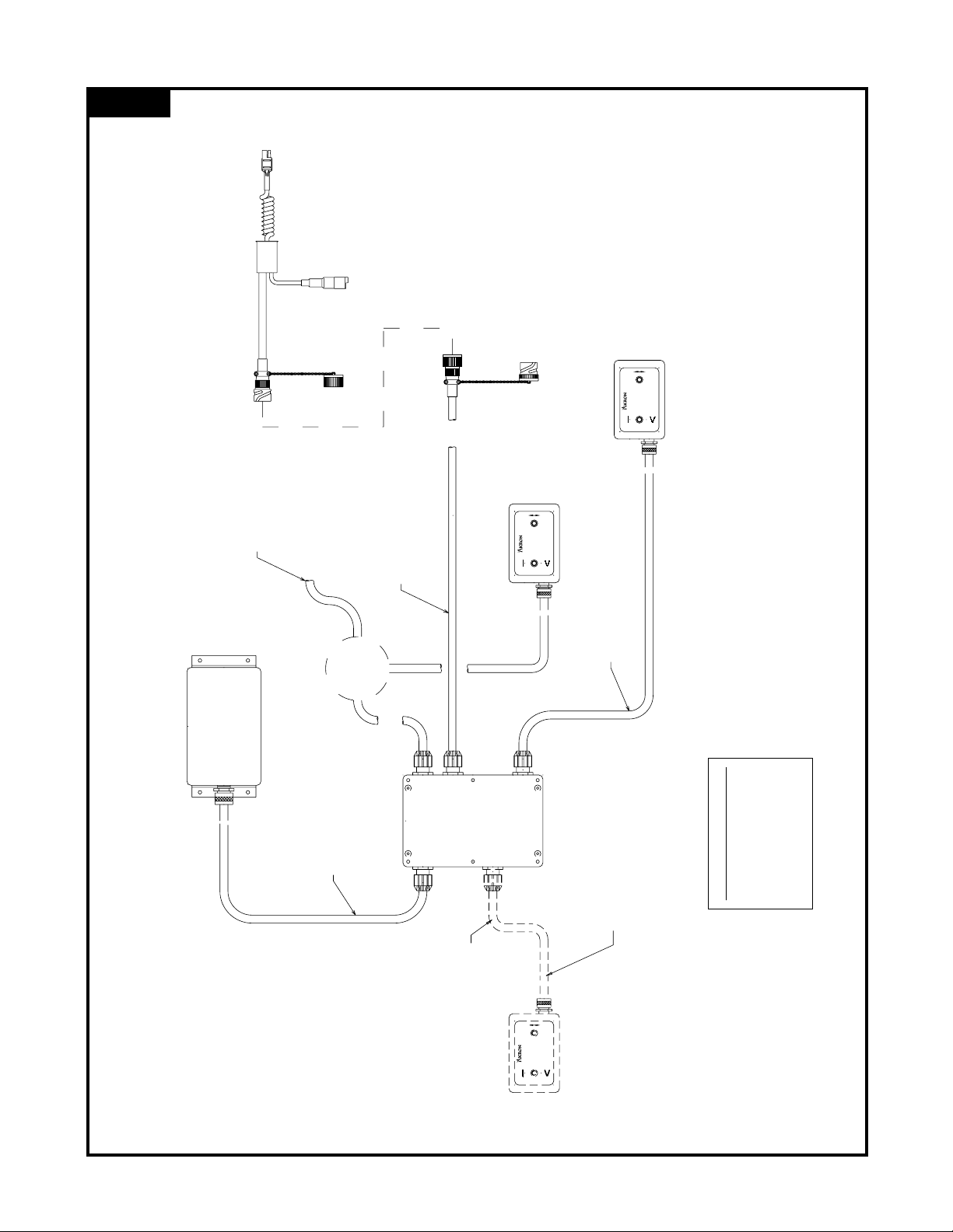
•Mount the logic box, control boxes and auxiliary battery out of Danger Zone (Figure 3).
ELECTRICAL INSTALLATION INSTRUCTIONS FOR ELECTRIC LADDER PIPE
A. CONTROL BOX WIRING AND ATTACHMENT
The Electric Ladder Pipe optional upper and lower controls use the same control box. The following steps
will prepare either one or both control boxes for attachment to the logic box.
STEP 1 If the control box includes an attached cable skip to STEP 6.
STEP 2 Determine the length of #20-7 cable needed, add 10 inches, then cut. For example, if a five
foot length of cable is needed, add 10 inches and cut the cable 5 foot 10 inches long.
STEP 3 Remove the cable grip nut and washer from the control box and put it on the cable with the
threads facing the box. On the same end of the cable remove 4 inches of the outer casing of
the cable and strip back 3/8 inch from each of the 7 wires.
STEP 4 Take the 7 ring terminals from the plastic bag and crimp them on the 7 wires. Remove the four
control box cover screws and set the control box cover
aside. Thread the 7 wires through the cable grip attached to
the control box and attach them to the proper terminals.
Tighten the cable grip nut and washer on the cable to the
cable grip on the control box to secure the cable. Reattach
control box cover and secure with the four screws.
STEP 5 Remove the cable grip nut from the plastic bag and put it on
the other end of the cable with the threads facing out.
Remove 6 inches of the outer cover and strip back 3/8 inch
from each of the 7 wires.
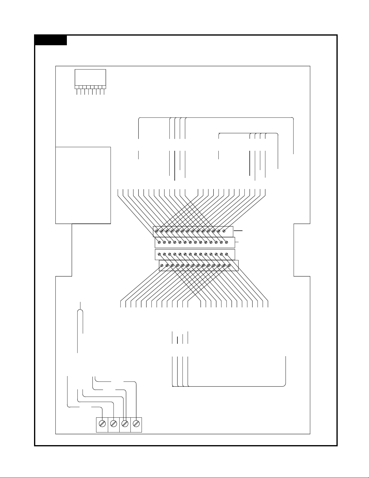
STEP 6 Remove the 6 logic box cover screws and set the logic box cover aside. Thread the 7 wires
through the upper or lower control hole in the logic box (see component layout, Figure 5).
Thread the cable grip washer and cable grip nut with the threads facing the box on the cable.
Pull enough cable through the cable grip to ensure a good fit. Tighten the cable grip nut and
attach the individual wires to the proper terminals (see wiring diagram Figure 6). Reattach the
logic box cover and secure with the 6 screws.
NOTE: The lower control and upper control wires must be attached to the correct terminals for
the lower control to override the upper control. The one attached to the Master terminal will
have the overriding capabilities.
B. LOGIC BOX / MONITOR WIRING HARNESS ATTACHMENT
These instructions are to attach the logic box / monitor wiring harness to the logic box.
STEP 7 Disconnect the logic box wiring harness from the monitor wiring harness (Figure 3). Remove the
cable grip nut from the logic box and put it on the wiring harness (#16-4) cable with the threads
facing out. Thread the wires through the appropriate cable grip hole on the logic box (Figure 3).
Pull enough cable through the cable grip to ensure a good fit. Tighten the cable grip nut and
attach the individual wires to the proper terminals (Figure 2).
NOTE: Do not extend the wiring harness. To ensure proper voltage, attach the supplied wiring
harness directly to logic box.
C. AUXILIARY BATTERY ATTACHMENT
The battery connections should be the last connection made.
Page 4
STRAIGHT
FOG
LOWER
RAISE
WHT
WHITE
WHT
BRN
BLUE
GREEN
YELLOW

Page 5
135135flflMAXIMUMMAXIMUM
13 1/3213 1/32
36 7/836 7/8
10 31/3210 31/32
Figure 1 DIMENSIONAL
SPECIFICATIONS
WARNING
▲
!
WARNING
▲
!
Note: View in unlocked position
Adjustable to any round aerial ladder rung up to 17⁄8”dia.
Rung spacing should not exceed 16”on centers for 21⁄2”
and 3”swivel, 147⁄16”on centers for 31⁄2”swivel.
Danger Zone
Elevation Stops

Page 6
TO MONITOR
20-5 CABLE
16-4 CABLE 20-5 CABLE
+12/24 VOLT
+12/24 VOLT
+12/24 VOLT
TO CONTROL BOX
TO CONTROL BOX
GROUND
GROUND
IND LIGHT
IND LIGHT
MASTER
SLAVE
WHT
TAN
YEL
GRN
BLU
WHT
RIGHT MOTOR
UP MOTOR
SLAVE
MASTER
8
1
28
27
26
25
24
23
22
21
20
19
18
17
16
14
13
12
11
10
9
8
7
6
5
4
3
2
1
15
28
27
26
25
24
23
22
21
20
19
18
17
16
15
14
13
12
11
10
9
8
7
6
5
4
3
2
1
BLK
RED
GRN
WHT
FOG
STREAM
UP
DOWN
TAN
YEL
GRN
BLU
FOG
STREAM
UP
DOWN
SS MOTOR
FOG MOTOR
DOWN MOTOR
LEFT MOTOR
28
2815
15
14
14
1
1
TB2 TB3 TB1
+12/24 VOLT AUX BATTERY (OPTIONAL)
+12/24 VOLT VEHICLE BATTERY TO VEHICLE BATTERY
–VEHICLE GROUND
AUX GROUND
4
1
Black
Green
White
DOWN
DOWN
DOWN
DOWN
DOWN
UP
UP
UP
Factory Settings
Figure 2 WIRING
SCHEMATIC

READ OPERATING INSTRUCTIONS BEFORE USE
SS
LOWERFOG
RAISE
READ OPERATING INSTRUCTIONS BEFORE USE
SS
LOWERFOG
RAISE
READ OPERATING INSTRUCTIONS BEFORE USE
SS
LOWERFOG
RAISE
UPPER CONTROL BOX
REEL
CABLE
OPTIONAL
OPTIONAL CONFIGURATION
20-7 CABLE
VEHICLE BATTERY
16-2 CABLE
(ATTACHED TO MONITOR)
(OPTION)
AUX. BATTERY
16-4 CABLE
LOGIC BOX
20-7 CABLE
WIRING HARNESS
UPPER CONTROL BOX
LOWER CONTROL BOX
WIRING HARNESS
(ATTACHED TO LOGIC BOX)
Figure 3 ELECTRICAL COMPONENT
LAYOUT
Controller Symbols
—Straight Stream
< Fog
→Right
↑ Up
Page 7

Page 8
Figure 4 MONITOR
ATTACHMENT
1
6
4
2
5
3

Page 9
STEP 8 AUXILIARY BATTERY –Remove the cable grip nut from the logic box and place it on the battery
(#16-3) cable with the threads facing out. Thread the wires through the appropriate cable grip
hole on the logic box (Figure 3). Pull enough cable through the cable grip to ensure a good fit.
Tighten the cable grip nut and attach the individual wires to the proper terminals (Figure 2).
D. CABLE REEL ATTACHMENT
These instructions are to attach the cable reel in between the logic box and the lower control box along
with the power source (Figure 3).
IMPORTANT CABLE REEL NOTE: YOU MUST SUPPLY ADEQUATE WIRE SIZE FOR THE POWER
SOURCE TO OPERATE THE MONITOR PROPERLY (equivalent to 12 awg). YOU MUST USE 20 AWG OR
LARGER FOR THE CONTROLLER WIRES. AKRON BRASS SUPPLIED CABLE REEL HAS 100 FOOT OF
USABLE CABLE. DO NOT EXTEND LADDER FURTHER THAN THE USABLE CABLE LENGTH.
STEP 9 Mount the cable reel in the desired position. Mount the guides at the beginning of each sec-
tion of the ladder. Place the cable through the guides and up to the logic box. Secure the
cable to the top portion of the ladder with cable clamps. Remove ball stop and place in appro-
priate position.
NOTE: Cable may not have same color of wires as shown on Figure 2. Label wire color to
function for future reference.
STEP 10 Remove the cable grip nut from the logic box and place it on the cable reel cable with the
threads facing out. Thread the wires through the appropriate cable grip hole on the logic box.
Pull enough cable through the grip to ensure a good fit. Tighten the cable grip nut and attach
the controller wires to the proper terminals (Figure 2).
STEP 11 Use the rest of the wires for the power source. You will need to use more than one wire for the
positive and negative connections if the wire size is smaller than 12 AWG. Make the appropri-
ate connections to the vehicle battery terminal and the ground terminal in the logic box.
Reattach the logic box cover and secure with the 6 screws.
STEP 12 Open the junction box on the cable reel. Attach the lower control box wires to the proper
color-coded wires. Attach the power leads in the junction box to the vehicle battery. Close the
junction box and test all functions before using.
NOTE: Wire color at junction box may not correspond to wire color at logic box. Use caution
and verify corresponding color of wires.
E. MECHANICAL MONITOR ATTACHMENT
This unit is equipped with a quick acting clamp which is adjustable to fit the rung spacing of most aerial
ladders. It is pre-set at the plant to fit a rung spacing of 151⁄4”and it may be necessary to adjust the spac-
ing to your ladder.
NOTE: Round rung ladders require different clamps than square rung ladders. Do not use if clamps do not
match rung shape. Contact Akron Brass for clarification.
To install the pipe on your aerial, follow the simple steps outlined below (Figure 4).
1. Hook upper clamp (1) over top rung and drop the pipe into position.
2. To unlock the handle, compress the safety catch (2) completely with palm of your hand.
3. Raise locking handle (3) completely.
4. Place lower clamp (4) under the second rung and lower the locking handle into the fully locked posi-
tion.
5. If your rung spacing is other than 151⁄4”, you will need to adjust the position of the lower bracket.
6. Loosen the five screws both front (5) and rear (6).
7. With the handle in the locked position, slide the entire lower bracket until the second rung fits snugly
into the bottom of the lower clamp. (You may need to lightly tap the bracket with a leather or rubber
mallet.)
8. Unlock the handle as described in Steps 2 and 3 and slide the entire bracket upward approximately 1⁄16”
to 1⁄8”or until the unit will lock into place tightly. CAUTION: Be careful not to have the clamps too
▲
!

Page 10
tight when in the locked position.
9. Snug down rear screw (6) and then securely tighten front screw (5) and the rest of the screws (5 & 6) to
approximately 100-125 in-lbs. Do not over-tighten middle screw (5).
10. Test the safety catch operation to ensure proper locking action before putting the unit into service.
NOTE: Periodically check for wear between the safety catch (2) and the locking handle (3). If excessive
wear should become apparent, the locking mechanism should be replaced immediately.
OPERATING INSTRUCTIONS FOR ELECTRIC LADDER PIPE
A. UPPER AND LOWER CONTROL OPERATION
The upper and lower control boxes are used to control the monitor and nozzle. To change the nozzle pat-
tern toward the “straight stream”or “fog”position press the proper toggle switch toward “STRAIGHT”or
“FOG”respectively. To change the vertical monitor position upward or downward press the proper toggle
switch toward “RAISE”or “LOWER”respectively.
THE LOWER CONTROL BOX FUNCTIONS WILL OVERRIDE THE UPPER CONTROL BOX FUNCTIONS IN
COMPLIANCE WITH THE REQUIREMENTS OF THE NFPA STANDARD. NOTE: THE LOWER CONTROL
AND UPPER CONTROL WIRES MUST BE ATTACHED TO THE CORRECT TERMINALS FOR THE LOWER
CONTROL TO OVERRIDE THE UPPER CONTROL. NONE OF THE FUNCTIONS CAN BE CONTROLLED
FROM THE UPPER CONTROL BOX WHEN ANY OF THE SWITCHES ON THE LOWER CONTROL BOX ARE
ACTIVATED.
B. ELEVATION STOPS
The elevation stop sets the upper limit of the elevation. The monitor is shipped with the elevation stop at
90°above horizontal and can travel 45˚below horizontal. The vertical position of 45°, 60°and 75°above
horizontal can be achieved by switching the stop to the desired locations located on the elevation gear
(Figure 1).
C. MANUAL OVERRIDE CONTROL
THE MANUAL OVERRIDE CONTROL IS TO BE USED WHEN THE POWER TO THE MONITOR IS OFF. One
override crank is attached, for the vertical control. It is 1⁄4 inch in size. A 1⁄4 inch Allen wrench will also actuate
the overrides. To use the manual override pull the key pin which holds the override crank in place and insert
the hex head end of the override crank in the hexagon shaped hole beside the crank storage bracket. Then
rotate or spin the override crank either clockwise or counterclockwise to aim the monitor in the desired direc-
tion.
WHEN THE OVERRIDE CRANKS ARE NO LONGER IN USE PUT THEM BACK IN THE STORAGE POSI-
TION. DO NOT USE THE ELECTRIC CONTROLS WHEN THE OVERRIDE CRANKS ARE BEING USED OR
ARE IN POSITION FOR USE.
D. NOZZLE PRESSURE
Do not exceed the following discharge pressure with straight tips.
Tip Size Pressure
11⁄4”100 PSI (690 KPA)
13⁄8”100 PSI (690 KPA)
11⁄2”100 PSI (690 KPA)
13⁄4”100 PSI (552 KPA)
2”70 PSI (488 KPA)
Do not exceed 1000 GPM (3800 LPM) when using a fog nozzle.
OPERATING INSTRUCTIONS FOR SABERMASTER NOZZLE
DETERMINING FLOW
The SaberMaster has two operating positions - Smooth Bore and Adjustable Fog.
1. Push the Pattern Control Switch towards Straight Stream position to operate in Smooth Bore.

2. Push the Pattern Control Switch towards Fog to operate in Fog. Once the Smooth Bore streams have completely
shut off, the Fog stream is in a narrow pattern. By continuing to hold down the Control Switch, the pattern will widen
to full wide fog. The stream can be stopped between narrow and wide by releasing the switch.
3. To go back to Smooth Bore, push the Pattern Control Switch towards Straight Stream until the Fog stream has com-
pletely shut off.
4. The SaberMaster has a manual override feature which allows the stream position to be manually operated. Place a
1/4" hex wrench into the hex socket at the discharge end of the motor assembly. From the discharge end, turn the
hex wrench clockwise to go into Smooth Bore and counter-clockwise to go into Fog.
MAINTENANCE INSTRUCTIONS FOR ELECTRIC LADDER PIPE
Your Electric Ladder Pipe monitor and nozzle should be inspected prior to and after each use, to ensure it is in good
operating condition. Periodically, an unanticipated incident occurs where the Ladder Pipe is misused in a manner that
is inconsistent with standard operating practices and those listed in IFSTA. A partial list of potential misuse includes:
•Operating above maximum rated pressure and flow.
•Not draining, and allowing water to freeze inside.
•Prolonged exposure to temperatures above 130°F, or below -25°F.
•Operating in a corrosive environment.
•Having the Ladder Pipe nozzle hit a fixed object during operating or transportation.
•Other misuse that might be unique to your specific environment.
Also there are many “tell tale”signs that indicate repair is in order, such as:
•Controls that are either inoperable or difficult to operate.
•Excessive wear.
•Poor discharge performance.
•Water leaks.
If any of the above situations are encountered, the Electric Ladder Pipe should be taken out of service, repaired, and
tested by a qualified technician before placing it back in service.
MAINTENANCE FOR SABERMASTER NOZZLE
• Under normal conditions, periodically flushing the nozzle with clean water and and cleaning grit and dirt from around
exterior moving parts will allow the nozzle to operate as designed.
• Over time, the seals may need to be replaced. This can be accomplished by returning the nozzle to Akron Brass for
repair.
MOTOR REPLACEMENT FOR ELECTRIC LADDER PIPE
To replace the vertical rotational motor:
1) Disconnect Power from the unit.
2) Loosen and remove the four socket screws (Item 23 on the Parts List) from the gearbox housing.
3) Slowly remove the motor assembly (25) and motor adapter (6) from the unit.
4) Loosen and remove the 4 socket head capscrews (26) from the inside of the motor adapter that hold the housing
and the motor assembly together.
5) Remove motor adapter (6) from the motor assembly (25).
6) Replace both O-ring seals (21 & 27) on the motor adapter (6).
7) Attach the new motor assembly (25) to the motor adapter (6) making sure all four screws (26) are tight.
8) Install the motor and motor adapter assembly to the unit making sure all four socket screws (23) are tight. It may be
necessary to rotate the motor slightly to get the motor gear to line up with the gears inside the gearbox.
9) Restore power to the unit.
10) Test the operation of the unit.
Call Akron Brass Customer Service Department if any problems are encountered.

© Premier Farnell Corporation. 2000 All rights reserved. No portion of this can be
reproduced without the express written consent of Premier Farnell Corporation.
P ONE: 330.264.5678 or 800.228.1161 IFAX: 330.264.2944 or 800.531.7335 Iwww.akronbrass.com
Available in Canada through AKRON MANUFACTURING COMPANY
P ONE: 519.773.8431 IFAX: 519.773.3794
WARRANTY AND DISCLAIMER: We warrant Akron Brass products for a period of five (5) years after purchase against defects in materials or workmanship. Akron Brass will repair or replace prod-
uct which fails to satisfy this warranty. Repair or replacement shall be at the discretion of Akron Brass. Products must be promptly returned to Akron Brass for warranty service.
We will not be responsible for: wear and tear; any improper installation, use, maintenance or storage; negligence of the owner or user; repair or modification after delivery; damage; failure to fol-
low our instructions or recommendations; or anything else beyond our control. WE MAKE NO WARRANTIES, EXPRESS OR IMPLIED, OT ER T AN T OSE INCLUDED IN T IS WARRANTY STATE-
MENT, AND WE DISCLAIM ANY IMPLIED WARRANTY OF MERC ANTABILITY OR FITNESS FOR ANY PARTICULAR PURPOSE. Further, we will not be responsible for any consequential, incidental
or indirect damages (including, but not limited to, any loss of profits) from any cause whatsoever. No person has authority to change this warranty.
ISO 9001 REGISTERED COMPANY
REVISED 06/05
NOTES
This manual suits for next models
1
Table of contents
Other Akron Plumbing Product manuals