U.S. Patent No. 8,856,780
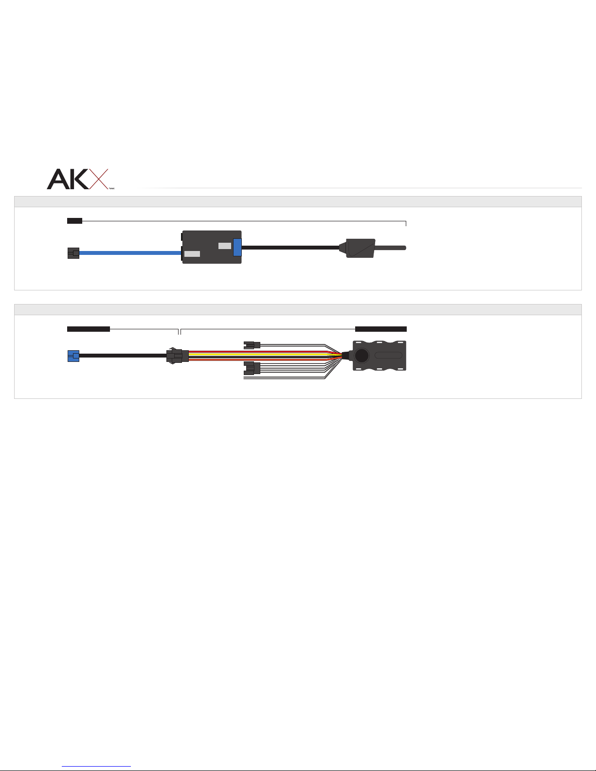
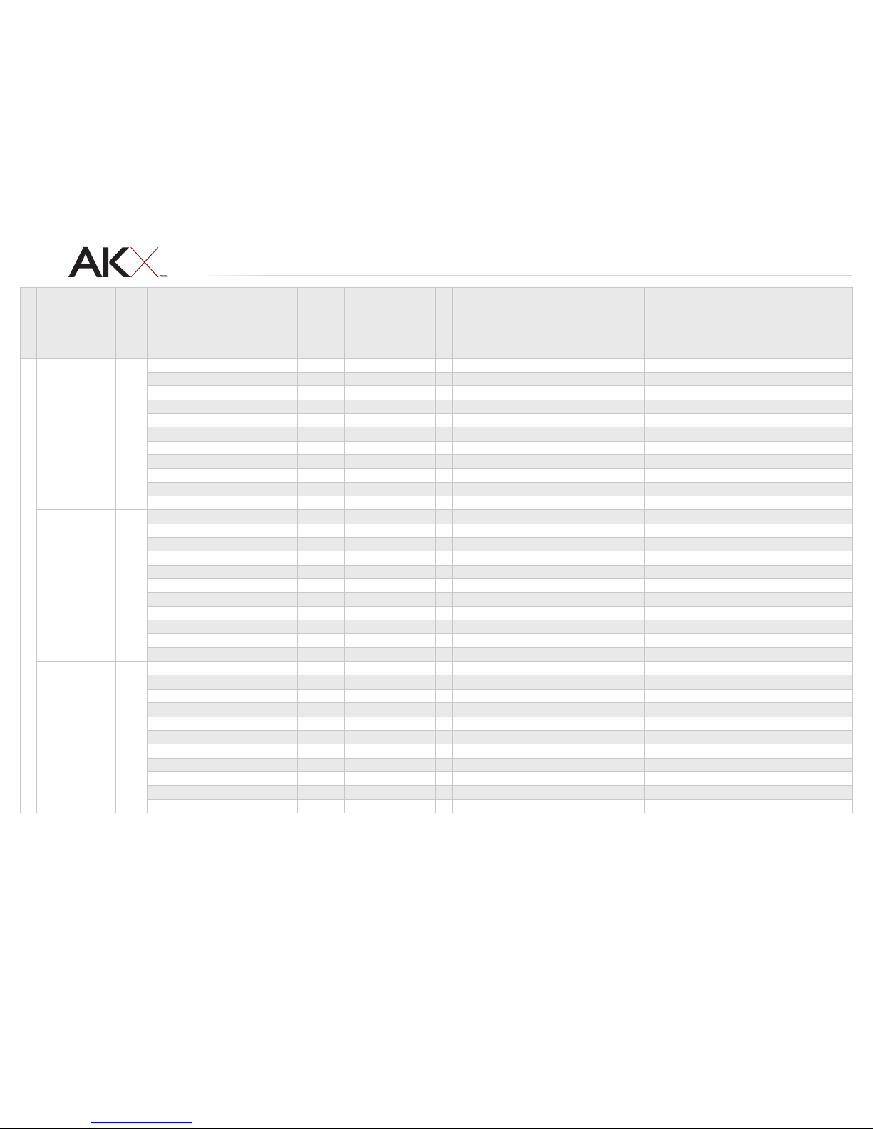
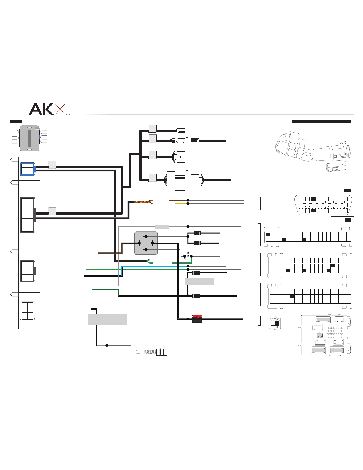
TYPE 2 - WIRE CHART - 1 OF 2
MAKE
MODEL
YEAR
WIRE
DESCRIPTION
CONNECTOR
NAME
CONNECTOR
COLOR
CONNECTOR
TYPE
POSITION
WIRE
COLOR
POLARITY
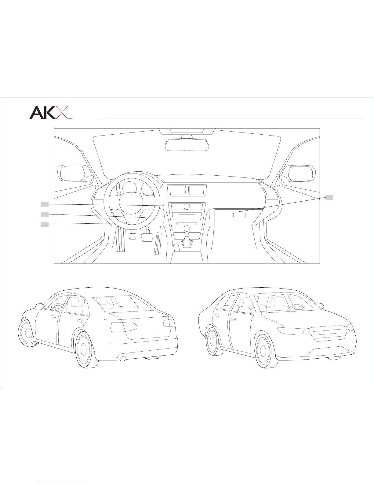
MODULE
LOCATION
COMPONENT
LOCATOR
FORD
C-MAX
STD key
AT
13-14
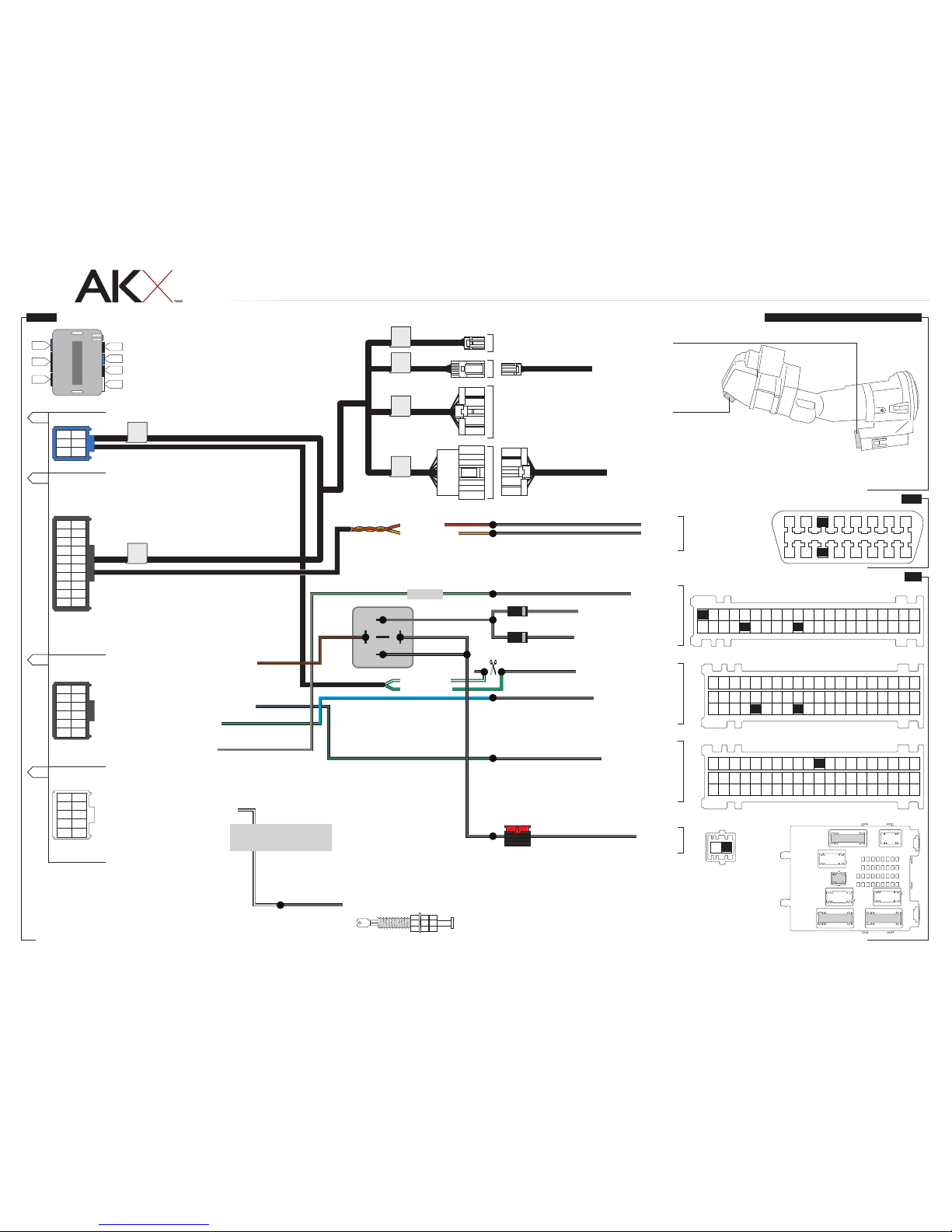
CanH C251 White 16 pin 03 Gray/Orange (DATA) OBDII connector C
CanL C251 White 16 pin 11 Purple/Orange (DATA) OBDII connector C
Parking Light Left C2280A LtGreen 42 pin 01 Yellow/Blue (+) BCM, behind glove box D
Parking Light Right C2280A LtGreen 42 pin 26 Brown/Yellow (+) BCM, behind glove box D
Horn C2280A LtGreen 42 pin 31 Purple/Green (-) BCM, behind glove box D
Driver Door Pin C2280B Brown 60 pin 45 Green/Purple (OPEN) BCM, behind glove box* D
Trunk Release C2280B Brown 60 pin 49 Brown (-) BCM, behind glove box D
Lock C2280B Brown 60 pin 36 Gray/Yellow (-) BCM, behind glove box* D
Unlock C2280C Blue 60 pin 26 Purple/Gray (-) BCM, behind glove box* D
Driver Unlock C2280B Brown 60 pin 55 ~ (-) BCM, behind glove box* D
12V C2280G ~ 02 pin 02 Red (+) BCM, behind glove box D
Escape
STD key
AT
13-14
CanH C251 White 16 pin 03 Gray/Orange (DATA) OBDII connector C
CanL C251 White 16 pin 11 Purple/Orange (DATA) OBDII connector C
Parking Light Left C2280A LtGreen 42 pin 01 LtGreen/Orange (+) BCM, behind glove box D
Parking Light Right C2280A LtGreen 42 pin 26 Brown/Yellow (+) BCM, behind glove box D
Horn C2280A LtGreen 42 pin 31 Purple/Green (-) BCM, behind glove box D
Driver Door Pin C2280B Brown 60 pin 45 Green/Purple (OPEN) BCM, behind glove box* D
Trunk Release C2280B Brown 60 pin 49 Brown (-) BCM, behind glove box D
Lock C2280B Brown 60 pin 36 Gray/Yellow (-) BCM, behind glove box* D
Unlock C2280C Blue 60 pin 26 Purple/Gray or Purple/Orange (-) BCM, behind glove box* D
Driver Unlock C2280B Brown 60 pin 55 Blue/Brown (-) BCM, behind glove box* D
12V C2280G ~ 02 pin 02 Red (+) BCM, behind glove box D
Focus
STD key
AT
14
CanH C251 White 16 pin 03 Gray/Orange (DATA) OBDII connector C
CanL C251 White 16 pin 11 Purple/Orange (DATA) OBDII connector C
Parking Light Left C2280A LtGreen 42 pin 01 Yellow/Blue (+) BCM, behind glove box D
Parking Light Right C2280A LtGreen 42 pin 26 Brown/Yellow (+) BCM, behind glove box D
Horn C2280A LtGreen 42 pin 31 Purple/Green (-) BCM, behind glove box D
Driver Door Pin C2280B Brown 60 pin 45 Green/Purple (OPEN) BCM, behind glove box* D
Trunk Release C2280B Brown 60 pin 49 Brown (-) BCM, behind glove box D
Lock C2280B Brown 60 pin 36 Empty (-) BCM, behind glove box* D
Unlock C2280C Blue 60 pin 26 Empty (-) BCM, behind glove box* D
Driver Unlock C2280B Brown 60 pin 55 Green/Purple (-) BCM, behind glove box* D
12V C2280G ~ 02 pin 02 Red (+) BCM, behind glove box D
* Wire also found in driver door harness.
www.autokinetix.comAutomotive Data Solutions Inc. © 2014 AKXFORSFO1CAKXFO1EN
PAGE 8 OF 20
• 20141203
DOC.: #18624