Xpresskit XK09 User manual

Update Alert: Firmware updates are posted to the web on a regular basis. We recommend
that you check for firmware and/or install guide updates prior to installing this product.
Rev.: 20120210
Platform: XK09
Firmware: CHRYSLER Remote Start Ready Installation
The Mobile Integration Systems
© 2012 Directed. All rights reserved.
† Chrysler, Dodge, Jeep and Volkswagen are registered trademarks and property of their respective companies.
Installation Guide
Important!
This product is NOT compatible with vehicles equipped with a manual transmission.
This guide supports the installation of a XK09 in Remote Start Ready (RSR) mode with or without a
Plug & Play ( ) T-Harness (Optional). This solution offers two configuration options
to control your system; 3x OEM Lock Remote Start Activation*, RF Kit (all sold separately). Refer to
page 17 for a list of RF kits and their part numbers.
CHTHX1 & CHTHX2
*3x OEM Lock Remote Start Activation is a feature that enables you to start/stop the vehicle using the
OEM remote. Press the OEM remote LOCK button three (3) times within three (3) seconds to start the
vehicle. To stop the vehicle, press the LOCK button three (3) more times.
The OEM remote lock and unlock functions are inactive when the key is inserted into the ignition;
therefore, the 3x OEM Lock Remote Start Activation feature cannot be used for Pit Stop mode.
Remote Start Ready (RSR) is a function that enables the interface module to remote start the vehicle
on its own. Consequently, there is no need for an aftermarket or an OEM remote starter in order to
start the vehicle from a distance.
completely
Vehicle Application Guide
Installation
........................................................................................................................................................................
Type 1a (with T-Harness).......................................................................................................................................................................
Type 1b (without T-Harness)..................................................................................................................................................................
Type 2a (with T-Harness).......................................................................................................................................................................
Type 2b (without T-Harness)..................................................................................................................................................................
Type 3a (with T-Harness).......................................................................................................................................................................
Type 3b (without T-Harness)..................................................................................................................................................................
Type 4 (without T-Harness)....................................................................................................................................................................
Module Programming for Type 1 to 3......................................................................................................................................................
.......................
.......................
.......................
........................
02
03
04
06
07
09
10
12
Programming
14
................................................................................ 15
LED Diagnostics and Troubleshooting............................................................................................................................. 16
Optional RF Kits............................................................................................................................................................... 17
Using a XK09-CHRYSLER RSR............................................................................................................................................................. 19
Limited One-Year Consumer Warranty............................................................................................................................ 21
Module Programming for Type 4 and Reset.....................................
Index

Rev.: 20120210
Platform: XK09
Firmware: CHRYSLER Remote Start Ready Installation
The Mobile Integration Systems
© 2012 Directed. All rights reserved.
Vehicle Application Guide Page 2
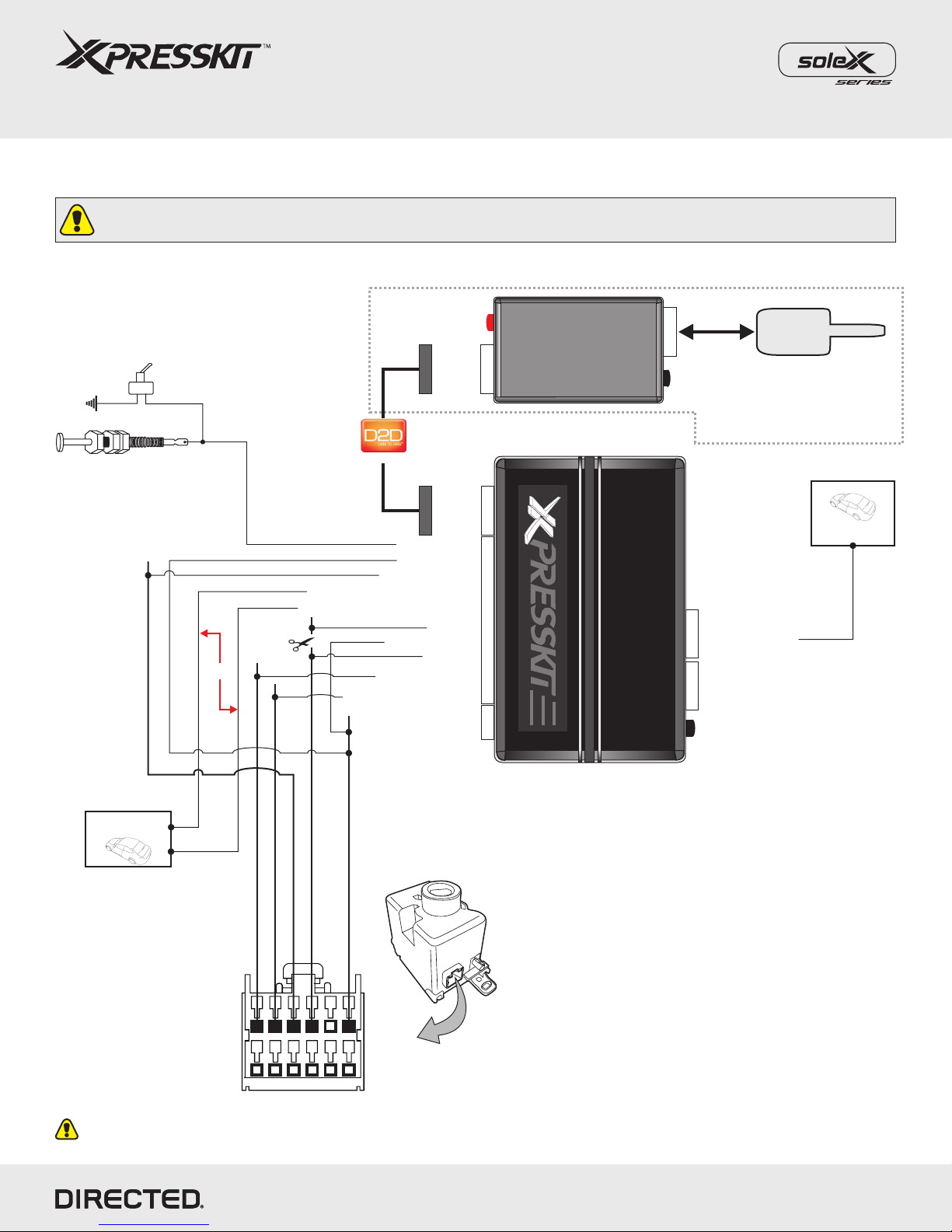
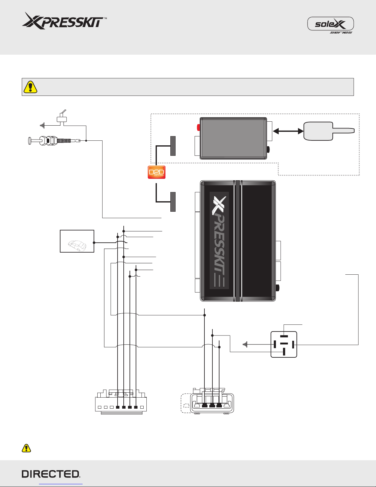
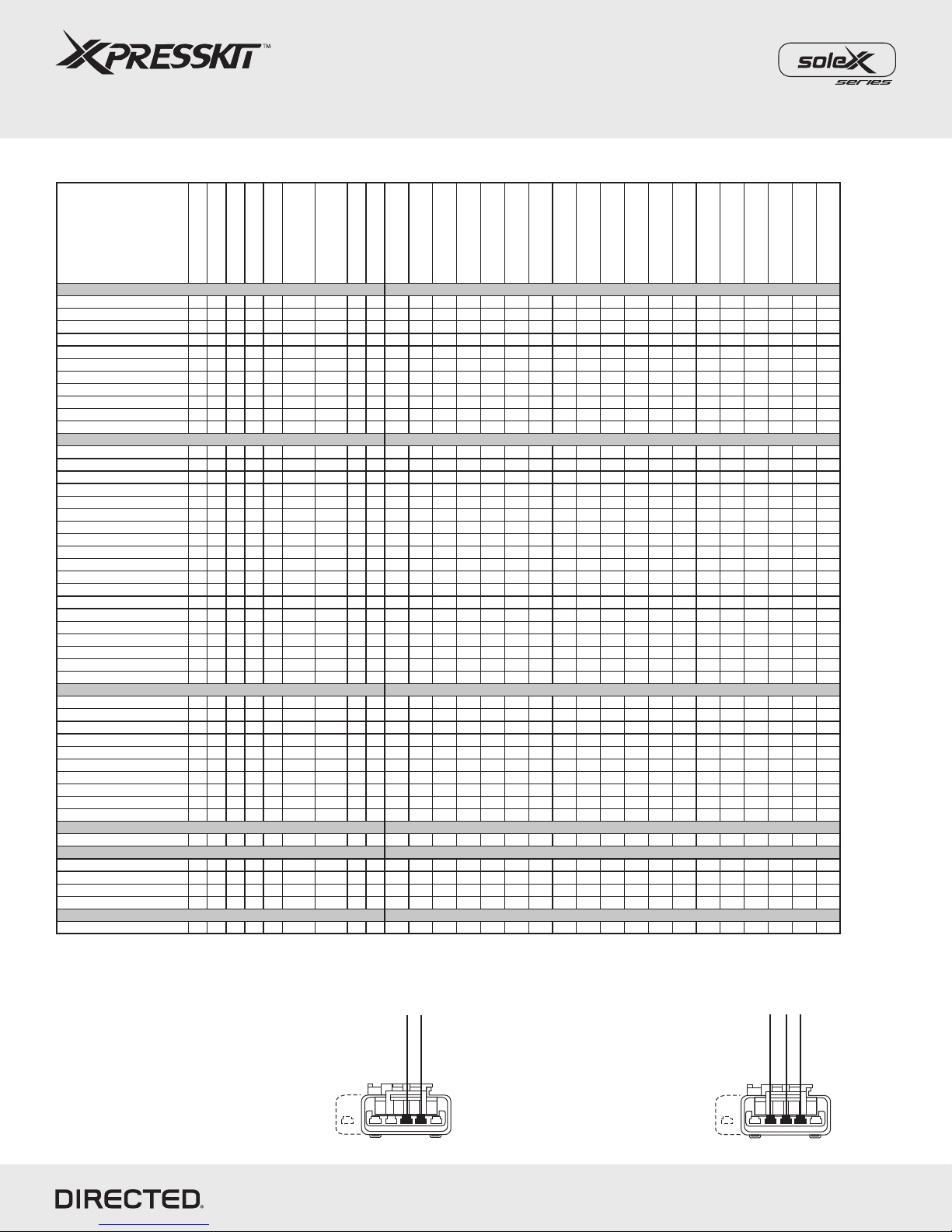
(+) Start, Pin 4
No Start wire
1
1
Connector side view
at ignition switch
Connector side view
at ignition switch
5 or 6
5 or 6
Installation Type 2 does not
have a Start wire
Installation Type 3
has a Start wire
*To select the proper install type, locate the ignition switch connector and select your install type as illustrated below:
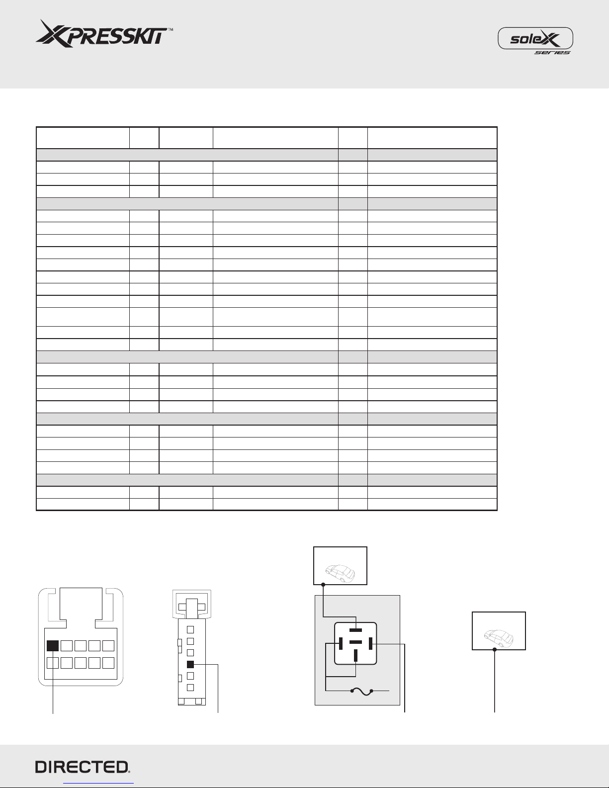
Vehicles
2012
2011
2010
2009
2008
2007
2006
2005
2004
DL-Arm Factory Security
DL-Disarm Factory
Security
DL-Door Lock Control
DL-Door Unlock
DL-Sliding Door Control
Driver
DL-Sliding Door Control
Passenger
DL-Trunk / Hatch Release
KI-Chrysler MUXX
Activation
KI-Key & Ignition.switch
Interface
PK-Immobilizer Bypass-
Data No Key Req'd
RS-3x LOCK START (Start
control using OEM Remote)
RS-RAP Shut Down
(Remote ACC Power)
RS-Remote Start Ready
RS-Tach / RPM Output
SS-Entry Monitoring ALL
Door Pins
SS-Entry Monitoring Driver
Door Pin
SS-Entry Monitoring
Trunk/Hatch Pin
ST-Brake Status (foot
brake)
ST-Hand Brake Status
Chrysler
200 2 • • • • • • • D • D • • D • D D
300/300c 1 1 1 • • • • • • • D D • D D
300/300c 3 3 3 • • • • • • • D • D • • D • D D
Aspen 2 2 2 • • • • • • • D • D • • D • D D
Pacifica 4 4 4 4 4 • • • • • • • D D • • D • D
PT Cruiser 3 3 3 3 3 • • • • • • D • D • • D • D D
Sebring 2 2 2 2 • • • • • • • D • D • • D • D D
Sebring Convertible 2 2 2 • • • • • • • D • D • • D • D D
Sebring Sedan 2 2 2 2 • • • • • • • D • D • • D • D D
Town & Country 1 1 1 1 1 • • • • • • • • • D D • • D • D D
Town & Country 4 4 4 4 • • • • • • • • • D D • • D • D
Dodge 12 11 10 09 08 07 06 05 04
Avenger 2 2 2 2 • • • • • • • D • D • • D • D D
Caliber 2 2 2 2 2 or 3* 2 or 3* • • • • • • D • D • • D • D D
Caravan 1 1 1 1 1 • • • • • • • • • D D • • D • D D
Caravan 4 4 4 4 • • • • • • • • • D D • • D • D
Challenger 1 1 1 1 • • • • • • • D D • • D • D D
Challenger (Smart Key) 1 1 1 1 • • • • • • • D D • • D • D D
Charger 1 1 1 • • • • • • • D D • D D
Charger 3 3 • • • • • • • D • D • • D • D D
Dakota 2 2 2 2 2 • • • • • • D • D • • D D D
Durango 1 • • • • • • D D • • D • D D
Durango 2 2 2 • • • • • • D • D • • D • D D
Grand Caravan 1 1 1 1 1 • • • • • • • • • D D • • D • D D
Grand Caravan 4 4 4 4 • • • • • • • • • D D • • D • D
Journey 1 1 • • • • • • D D • • D • D D
Magnum 1 • • • • • • D D • D D
Magnum 3 3 3 • • • • • • D • D • • D • D D
Nitro 2 2 2 2 2 • • • • • • D D • • D • D D
RAM 1 1 1 1 • • • • • • D D • • D D D
RAM 2 2 2 or 3* • • • • • • D • D • • D D D
Jeep 12 11 10 09 08 07 06 05 04
Commander 1 1 1 • • • • • • • D D • D D
Commander 3 3 • • • • • • • D • D • • D • D D
Compass 2 2 2 2 2 • • • • • • D • D • • D • D D
Grand Cherokee 1 1 1 1 1 • • • • • • D D • D D
Grand Cherokee 3 3 3 • • • • • • D • D • • D • D D
Grand Cherokee (Smart Key) 1 1 • • • • • • D D • D D
Liberty 2 2 2 2 • • • • • • D • D • • D • D D
Patriot 2 2 2 2 2 2 • • • • • • D • D • • D • D D
Wrangler 2 2 2 2 2 2 • • • • • • D • D • • D • D D
Wrangler Unlimited 2 2 2 2 2 2 • • • • • • D • D • • D • D D
Mitsubishi 12 11 10 09 08 07 06 05 04
Raider 2 2 2 • • • • • • D • D • • D D D
Ram
1500 1 • • • • • • D D • • D D D
2500 1 • • • • • • D D • • D D D
3500 1 • • • • • • D D • • D D D
C/V 1 • • • • • • • • • D D • • D • D D
Volkswagen 12 11 10 09 08 07 06 05 04
Routan 1 1 1 1 • • • • • • • • • D D • • D • D D
Legend:
D: Data-to-Data (D2D) only DL: OE Door Lock & Alarm Controls PK: Transponder & Immobilizer Override SS: Entry Point Status-Security
•: D2D and Wire-to-Wire (W2W) KI: Ignition Key Sw itch Interf ace RS: Engine Start & Status ST: Function/Feature Status

Rev.: 20120210
Platform: XK09
Firmware: CHRYSLER Remote Start Ready Installation
The Mobile Integration Systems
© 2012 Directed. All rights reserved.
Installation Type 1a (with T-Harness)
Page 3
Programming Button
4
4
4
20 2
XK09
Facing view
Behind Ignition Switch
Ignition
Barrel
LED
Programming
Button
4
4
XL202
Antenna
XOVER
2: Green: RAP OFF
3: -
4: -
CHTHX1
(optional)
(+)12v
TX
(-) Ground
RX
(+) 12v
RX
(-) Ground
TX
The optional XL202 and
antenna are not included and
MUST be purchased separately.
Hood Pin
Neutral Safety Switch
13: Violet/Brown: Parking Light MUX*
5: Blue: (-) Hood
See page 5 for
wiring information
1: -
Wires are listed by pin numbers. This display is not representative of connector pin layouts, which are often stacked.
*See Parking Lights wiring reference chart for the appropriate Parking Lights configuration.
OR*
(-) Driver door pin
Purple wire in
driver kick panel
Important!
The Hood Pin and Neutral Safety Switch are mandatory security devices, but are NOT supplied with the XK09.
11: Black/White: (-) Parking Lights via Relay*

Rev.: 20120210
Platform: XK09
Firmware: CHRYSLER Remote Start Ready Installation
The Mobile Integration Systems
© 2012 Directed. All rights reserved.
Installation Type 1b (without T-Harness)
Page 4
Programming Button
4
4
4
20 2
XK09
LED
Programming
Button
4
4
XL202
Antenna
XOVER
2: Green: RAP OFF
3: -
4: -
(+)12v
TX
(-) Ground
RX
(+) 12v
RX
(-) Ground
TX
The optional XL202 and
antenna are not included and
MUST be purchased separately.
Hood Pin
Neutral Safety Switch
5: Blue: (-) Hood
See page 5 for
wiring information
1: -
Ignition
Barrel
1
6
12 7
Connector side view
at ignition switch
13: Violet/Brown: Parking Light MUX*
9: Red: (+) 12 V
10: Black: (-)Ground
15: Yellow
16: Brown: (+) 12 V
17: Orange
19: Tan:HS CAN Low
20: Tan/Black: HSCAN High
(+) Ignition, Pin 3
(+) 12 V, Pin 1
CAN High, Pin 5
(-) Ground, Pin 4
CAN Low, Pin 6
(-) Driver door pin
Purple wire in
driver kick panel
Wires are listed by pin numbers. This display is not representative of connector pin layouts, which are often stacked.
*See Parking Lights wiring reference chart for the appropriate Parking Lights configuration.
Important!
The Hood Pin and Neutral Safety Switch are mandatory security devices, but are NOT supplied with the XK09.
11: Black/White: (-) Parking Lights*
OR*

Rev.: 20120210
Platform: XK09
Firmware: CHRYSLER Remote Start Ready Installation
The Mobile Integration Systems
© 2012 Directed. All rights reserved.
Page 5
6
5
4
3
2
1
Light switch,
black 6-pin plug
Parking Light Vehicle Wiring Reference Chart (Type 1)
Vehicle Years Vehicle Wire Location on vehicle (+) / (-)
XK09 Output from
12 Pin connector
Chrysler
300/300c 2008-11 White/Brown Black connector at light switch, pin 1 MUX 13: Violet/Brown: Parking Lights MUX
Town & Country 2011+ White/Green Black connector at light switch, pin 3 MUX 13: Violet/Brown: Parking Lights MUX
Town & Country 2008-10 White/Brown Black connector at light switch, pin 1 MUX 13: Violet/Brown: Parking Lights MUX
Dodge
Caravan 2011+ White/Green Black connector at light switch, pin 3 MUX 13: Violet/Brown: Parking Lights MUX
Caravan 2008-10 White/Brown Black connector at light switch, pin 1 MUX 13: Violet/Brown: Parking Lights MUX
Challenger 2008-11 White/Brown Black connector at light switch, pin 1 MUX 13: Violet/Brown: Parking Lights MUX
Challenger (Smart Key) 2008-11 White/Brown Black connector at light switch, pin 1 MUX 13: Violet/Brown: Parking Lights MUX
Charger 2008-10 White/Brown Black connector at light switch, pin 1 MUX 13: Violet/Brown: Parking Lights MUX
Durango 2011+ White/Green Black connector at light switch, pin 3 MUX 13: Violet/Brown: Parking Lights MUX
Grand Caravan 2011+ White/Green Black connector at light switch, pin 3 MUX 13: Violet/Brown: Parking Lights MUX
Grand Caravan 2008-10 White/Brown Black connector at light switch, pin 1 MUX 13: Violet/Brown: Parking Lights MUX
Journey 2009-10 White/Purple Passenger kick panel (+) 11: Black/White: (-) Parking Lights
via Relay
Magnum 2008 White/Brown Black connector at light switch, pin 1 MUX 13: Violet/Brown: Parking Lights MUX
RAM 2009-12 White Black connector at light switch, pin 1 MUX 13: Violet/Brown: Parking Lights MUX
Jeep
Commander 2008-10 White/Dk. Blue Hazard light switch* (-) 11: Black/White: (-) Parking Lights
Grand Cherokee 2008-10 White/Dk. Blue Hazard light switch* (-) 11: Black/White: (-) Parking Lights
Grand Cherokee 2011+ White/Green Black connector at light switch, pin 1 MUX 13: Violet/Brown: Parking Lights MUX
Grand Cherokee (Smart Key) 2011+ White/Green Black connector at light switch, pin 1 MUX 13: Violet/Brown: Parking Lights MUX
Ram
1500 2012 White Black connector at light switch, pin 1 MUX 13: Violet/Brown: Parking Light MUX
2500 2012 White Black connector at light switch, pin 1 MUX 13: Violet/Brown: Parking Light MUX
3500 2012 White Black connector at light switch, pin 1 MUX 13: Violet/Brown: Parking Light MUX
C/V 2012 White Black connector at light switch, pin 1 MUX 13: Violet/Brown: Parking Light MUX
Volkswagen
Routan 2011+ White/Green Black connector at light switch, pin 3 MUX 13: Violet/Brown: Parking Light MUX
Routan 2009-10 White/Brown Black connector at light switch, pin 1 MUX 13: Violet/Brown: Parking Light MUX
* This connection will make the Hazard lights flash when remote started.
Light switch,
black 10-pin plug
7
2
6
1
10
5
9
4
8
3
13: Violet/Brown: Parking Light MUX* 13: Violet/Brown: Parking Light MUX*
(+) Passenger
kick panel
(-) Hazard Light
Switch
30
86 85
87
87a
To vehicle’s
(+) Parking Lights
Fuse 15A
+12v
11: Black/White: (-) Parking Lights 11: Black/White: (-) Parking Lights

Rev.: 20120210
Platform: XK09
Firmware: CHRYSLER Remote Start Ready Installation
The Mobile Integration Systems
© 2012 Directed. All rights reserved.
Installation Type 2a (with T-Harness)
Page 6
Programming Button
4
4
4
20 2
XK09
5: Blue: (-) Hood
Hood Pin
Neutral Safety Switch
11: Black/White: (-) Parking Lights
XOVER
30
86 85
87
87a
To vehicle’s
(+) Parking Lights
Fuse 15A
+12v
See page 8 for
wiring information
Wires are listed by pin numbers. This display is not representative of connector pin layouts, which are often stacked.
2: -
3: -
4: -
1: -
Important!
The Hood Pin and Neutral Safety Switch are mandatory security devices, but are NOT supplied with the XK09.
1 8
Connector side view
at ignition switch
CHTHX2
(optional)
LED
Programming
Button
4
4
XL202
Antenna
(+)12v
TX
(-) Ground
RX
The optional XL202 and
antenna are not included and
MUST be purchased separately.

Rev.: 20120210
Platform: XK09
Firmware: CHRYSLER Remote Start Ready Installation
The Mobile Integration Systems
© 2012 Directed. All rights reserved.
Installation Type 2b (without T-Harness)
Page 7
30
86 85
87
87a
Programming Button
4
4
4
20 2
XK09
LED
Programming
Button
4
4
XL202
Antenna
XOVER
2: -
3: -
4: -
(+)12v
TX
(-) Ground
RX
(+) 12v
RX
(-) Ground
TX
The optional XL202 and
antenna are not included and
MUST be purchased separately.
Hood Pin
Neutral Safety Switch
5: Blue: (-) Hood
See page 8 for
wiring information
To vehicle’s
(+) Parking Lights
Fuse 15A
+12v
13: Violet/Brown: Multiplex Output
9: Red: (+) 12 V
10: Black: (-)Ground
16: Brown: (+) 12 V
19: Tan:HS CAN Low
20: Tan/Black: HSCAN High
Wires are listed by pin numbers. This display is not representative of connector pin layouts, which are often stacked.
Important!
The Hood Pin and Neutral Safety Switch are mandatory security devices, but are NOT supplied with the XK09.
CAN Low, Pin 7
(+) 12 V, Pin 5
CAN High, Pin 6
(-) Ground, Pin 4
1 8
Connector side view
at ignition switch
(+) Ignition, Pin 3
MUX, Pin 1
11: Black/White: (-) Parking Lights
1: -
1: -
2: Pink/White: (+) Ignition Output
3: -
4: -

Rev.: 20120210
Platform: XK09
Firmware: CHRYSLER Remote Start Ready Installation
The Mobile Integration Systems
© 2012 Directed. All rights reserved.
Page 8
Vehicle Years Wire (+) / (-) Location
Chrysler
200 2011 White/Violet (+) Driver kick panel
Aspen 2007-09 Pink/Red (+) Driver kick fuse box, black 40-pin plug, pin 6
Sebring 2007-10 White/Violet (+) Driver kick panel
Sebring Convertible 2008-10 White/Violet (+) Driver kick panel
Sebring Sedan 2007-10 White/Violet (+) Driver kick panel
Dodge
Avenger 2008-11 White/Violet (+) Driver kick panel
Caliber 2007-11 White/Violet (+) Driver kick panel
Dakota 2007-11 Pink/Red (+) Underhood fuse box, black 20-pin plug, pin 15
Durango 2007-09 Pink/Red (+) Driver kick fuse box, black 40-pin plug, pin 6
Nitro 2007-11 White/Violet (+) Driver kick panel
RAM 2006-08 White/Gray (+) Above driver kick, gray 74-pin plug, pin 19
Jeep
Compass 2007-11 White/Violet (+) Driver kick panel
Liberty 2008-10 White/Violet (+) Driver kick panel
Patriot 2007-12 White/Violet (+) Driver kick panel
Wrangler 2007-12 White/Violet (+) Passenger kick panel
Wrangler Limited 2007-12 White/Violet (+) Passenger kick panel
Mitsubishi
Raider 2007-09 Pink/Red (+) Underhood fuse box, black 20-pin plug, pin 15
Parking Light Vehicle Wiring Reference Chart (Type 2)
46
55
65
20
10
3
29
58
59
61
72
64
17
16
15
14
11
60
17 38 44
31 37 68 74
Above driver kick,
gray 74-pin plug
Underhood fuse box,
black 20-pin plug
10
20
9
19
8
18
7
17
6
16
5
15
4
14
3
13
2
12
1
11
39 25
28
29
32
33 21
36 24
9
12
13
16
820
5
17
1
38 4
37 3
40 2
Driver kick fuse box,
black 40-pin plug

Rev.: 20120210
Platform: XK09
Firmware: CHRYSLER Remote Start Ready Installation
The Mobile Integration Systems
© 2012 Directed. All rights reserved.
Page 9
Programming Button
4
4
4
20 2
XK09
1 8
Connector side view
at ignition switch
5: Blue: (-) Hood
Hood Pin
Neutral Safety Switch
11: Black/White: (-) Parking Lights*
XOVER
Wires are listed by pin numbers. This display is not representative of connector pin layouts, which are often stacked.
Important!
The Hood Pin and Neutral Safety Switch are mandatory security devices, but are NOT supplied with the XK09.
Installation Type 3a (with T-Harness)
Cut Purple/Brown
wire, Pin 8
(on male end)
CHTHX2
(optional)
5 or 6 1
Connector side view
at ignition switch
(+) Start, Pin 4
Violet/Brown, Pin 2
15: Yellow: (+) Starter
*See Parking Lights wiring reference chart for the appropriate Parking Lights configuration.
LED
Programming
Button
4
4
XL202
Antenna
(+)12v
TX
(-) Ground
RX
The optional XL202 and
antenna are not included and
MUST be purchased separately.
See page 11 for
wiring information

Rev.: 20120210
Platform: XK09
Firmware: CHRYSLER Remote Start Ready Installation
The Mobile Integration Systems
© 2012 Directed. All rights reserved.
Page 10
Installation Type 3b (without T-Harness)
30
86 85
87
87a
Programming Button
4
4
4
20 2
XK09
LED
Programming
Button
4
4
XL202
Antenna
XOVER
2: -
3: -
4: -
4: -
(+)12v
TX
(-) Ground
RX
(+) 12v
RX
(-) Ground
TX
The optional XL202 and
antenna are not included and
MUST be purchased separately.
Hood Pin
Neutral Safety Switch
5: Blue: (-) Hood
1: -
1: -
13: Violet/Brown: Multiplex Output
9: Red: (+) 12 V
10: Black: (-) Ground
16: Brown: (+) 12 V
(+) 12 V
(-) Ground
19: Tan:HS CAN Low
15: Yellow: (+) Starter
20: Tan/Black: HSCAN High
Wires are listed by pin numbers. This display is not representative of connector pin layouts, which are often stacked.
Important!
The Hood Pin and Neutral Safety Switch are mandatory security devices, but are NOT supplied with the XK09.
CAN Low, Pin 7
(+) 12 V, Pin 5
CAN High, Pin 6
(-) Ground, Pin 4
1 8
Connector side view
at ignition switch
(+) Ignition, Pin 3
(+) Start, Pin 4
Violet/Brown, Pin 2
1
Connector side view
at ignition switch
5 or 6
11: Black/White: (-) Parking Lights*
2: Pink/White: (+) Ignition Output
3: -
See page 11 for
wiring information
*See Parking Lights wiring reference chart for the appropriate Parking Lights configuration.

Rev.: 20120210
Platform: XK09
Firmware: CHRYSLER Remote Start Ready Installation
The Mobile Integration Systems
© 2012 Directed. All rights reserved.
Page 11
46
55
65
20
10
3
29
58
59
61
72
64
17
16
15
14
11
60
17 38 44
31 37 68 74
Above driver kick,
gray 74-pin plug
Vehicle Years Wire (+) / (-) Location
Chrysler
300/300c 2005-07 White/Violet (+) Passenger kick panel
PT Cruiser 2006-10 White/Violet (+) Driver kick panel
Dodge
Caliber 2007-11 White/Violet (+) Driver kick panel
Charger 2006-07 White/Violet (+) Passenger kick panel
Magnum 2005-07 White/Violet (+) Passenger kick panel
RAM 2006 White/Gray (+) Above driver kick, gray 74-pin plug, pin 19
Jeep
Commander 2006-07 White/Dk. Blue (-) Hazard light switch*
Grand Cherokee 2005-07 White/Dk. Blue (-) Hazard light switch*
* This connection will make the Hazard lights flash when remote started.
Parking Light Vehicle Wiring Reference Chart (Type 3)
(+) Parking Lights
(see table for
location)
30
86 85
87
87a
To vehicle’s
(+) Parking Lights
Fuse 15A
+12v
11: Black/White: (-) Parking Lights
(-) Hazard Light
Switch
11: Black/White: (-) Parking Lights

Rev.: 20120210
Platform: XK09
Firmware: CHRYSLER Remote Start Ready Installation
The Mobile Integration Systems
© 2012 Directed. All rights reserved.
Page 12
Installation Type 4 (without T-Harness)
Wires are listed by pin numbers. This display is not representative of connector pin layouts, which are often stacked.
Important!
The Hood Pin and Neutral Safety Switch are mandatory security devices, but are NOT supplied with the XK09.
Parking Lights
Chrysler Pacifica
requires a resistor.
See diagram on
page 13
30
86 85
87
87a
Programming Button
4
4
4
20 2
XK09
1: -
2: Pink/White: (+) Ignition Output
3: Orange/Red: (+) Starter
4: -
15: Yellow
11: Black/White: (-) Parking Lights
5: Blue: (-) Hood
17: Orange
18: Green: J1850
9: Red: (+) 12 V
10: Black: (-) Ground
16
Module-Sentry Key
Remote Entry
(+) Ignition,Pin 4
Pin 2, J1850
(-) Ground, Pin 5
(+) 12 V, Pin 6
(+) Ignition, Pin 3
(+) Violet/Brown, Pin 2
(+) Start, Pin 4
Fuse 15A
+12v
Hood Pin
Neutral Safety Switch
TX
(-) Ground
RX
(+) 12 V
XOVER
1
Connector side view
at ignition switch
Only connect with Pacifica
13: Violet/Brown: Multiplex Output
LED
Programming
Button
4
4
XL202
Antenna
(+)12v
TX
(-) Ground
RX
The optional XL202 and
antenna are not included and
MUST be purchased separately.

Rev.: 20120210
Platform: XK09
Firmware: CHRYSLER Remote Start Ready Installation
The Mobile Integration Systems
© 2012 Directed. All rights reserved.
Page 13
Vehicle Years Wire (+) / (-) Location
Chrysler
Pacifica 2004-08 Brown/White (-1K) MUX Headlight switch, black 12-pin plug, pin 6
Town & Country 2004-07 White/Orange (+) Driver kick panel
Dodge
Caravan 2004-07 White/Orange (+) Driver kick panel
Grand Caravan 2004-07 White/Orange (+) Driver kick panel
Parking Light Vehicle Wiring Reference Chart (Type 4)
Headlight switch,
black 12-pin plug
12
6
11
5
10
4
9
3
8
2
7
1
OR
Positive (+) MUX
1KÙ
(+) Parking Lights
30
86 85
87
87a
30
86 85
87
87a
To vehicle’s
(+) Parking Lights
To vehicle’s
(MUX) Parking Lights
Fuse 15A
+12v
+12v
11: Black/White: (-) Parking Lights 11: Black/White: (-) Parking Lights

Rev.: 20120210
Platform: XK09
Firmware: CHRYSLER Remote Start Ready Installation
The Mobile Integration Systems
© 2012 Directed. All rights reserved.
Page 14
Module Programming for Type 1 to 3
4
2
5Turn the key back to the OFF position.
Insert the key into the ignition barrel and turn it to ON. Wait for the LED
to start flashing slowly.
Connect one or both of the other 4-pin harnesses, depending on the
requirements of each installation types.
START
OFF
KEY
Key at OFF
ON
Flashes
&
KEY
Key at ON
START
OFF
ON
1
The LED turns ON solid or flashes rapidly.
On Solid or Flashes
6
Press the UNLOCK button on the factory keyless
remote. The LED
then turns OFF.
The module is now programmed.
flashes quickly for 1 second,
turns ON solid for 3 seconds,
Refer to the LED Diagnostics section on page 16 for more information and for troubleshooting purposes.
6
Press the module programming
button. The LED flashes quickly for 1 second,
turns ON solid for 3 seconds, then turns OFF. The
module is now programmed.
&
LED Sequence
Press
Connect the 4-pin D2D harness to the XL202 module,
then connect the 20-pin harness.
Caution! The 20-pin connector can be easily plugged in backwards.
Important! If the LED does not flash quickly for 1 second at step 6, the module is NOT in RSR mode. Reset the module
and repeat the programming sequence. You must make sure the vehicle hood is open in step 3.
WITHOUT Factory Keyless Remote WITH Factory Keyless Remote
&
Press Unlock LED Sequence
4-pin
4-pin
20-pin
XL202
3Make sure the hood of the vehicle is open before proceeding to step 4.(Hood pin to Ground)
Caution! Failure to do so will NOT put the module in RSR mode and may cause
unexpected behavior in the car.

Rev.: 20120210
Platform: XK09
Firmware: CHRYSLER Remote Start Ready Installation
The Mobile Integration Systems
© 2012 Directed. All rights reserved.
Page 15
1
2
3
Disconnect the module from any power source.
Press and HOLD the programming button.
While holding the button, connect the module to the power source.
Wait until the red LED flashes once and release the programming
button.
Flashes Once
&
Release
Disconnect from Power
&
Press & Hold Connect to Power
Module Reset
Module Programming for Type 4
5
4
Turn the key to ON . The LED will
The module is now programmed and ready to use.
position
1 second, turns ON solid for 3 seconds, then turns OFF (it could take up
to 10 seconds).
flash slowly then quickly for
1
&
&
KEY
Key at ON
START
OFF
ON
KEY
Key at OFF
START
OFF
ON
Refer to the LED Diagnostics section on page 16 for more information and for troubleshooting purposes.
Important! If the LED does not flash quickly for 1 second at step 5, the module is NOT in RSR mode. Reset the module
and repeat the programming sequence. You must make sure the vehicle hood is open in step 3.
LED Sequence
LED Sequence
The LED turns ON solid.
On Solid
Connect the 4-pin D2D harness to the XL202 module,
then connect the 20-pin harness.
Caution! The 20-pin connector can be easily plugged in backwards.
4-pin
20-pin
XL202
3
2Connect one or both of the other 4-pin harnesses, depending on the
requirements of each installation types. 4-pin
Make sure the hood of the vehicle is open before proceeding to step 4.(Hood pin to Ground)
Caution! Failure to do so will NOT put the module in RSR mode and may cause
unexpected behavior in the car.
Insert the key into the ignition barrel to the OFF position. Wait for the LED
to start flashing quickly.

Rev.: 20120210
Platform: XK09
Firmware: CHRYSLER Remote Start Ready Installation
The Mobile Integration Systems
© 2012 Directed. All rights reserved.
Page 16
LED Diagnositics and Troubleshooting
LED Status
Description Troubleshooting
During Power Up
Flashes quickly
for 1 second Module is in Standalone mode. Normal operation.
Solid The bus type cannot be
detected.
Make sure the T-Harness is properly connected and
insert the key in the ignition switch.
Flashes quickly The vehicle type is not yet
detected.
Insert the key in the ignition switch and turn to the ON
position. You may need to wait up to 10 seconds.
Flashes slowly Waiting for keyless. Remove the key from the ignition switch and press
Unlock on the factory remote.
Solid for 3
seconds
Module was successfully
programmed or is already
programmed.
Normal operation.
Flashes once
quickly Modules was reset. Normal operation if the Programming button was held
during the power up sequence.
Off Module has no power. Check the power connections.
Remote Start Period
Solid Incorrect behavior. Data is not processing correctly. Disconnect the power
from the module and power up.
Off No Start command was received.
Make sure the module was programmed with the hood
open (Ground on Blue wire). If not, reset the module and
reprogram it with the hood open.
Flashes for 1
second A command is processing. Normal operation upon receiving a command from the
remote.
Flashes The unit is in a remote start
sequence. Normal operation during runtime.
Programmed & Installed (Idle)
Off The unit is waiting for a
command. Normal operation.
Flashes for 1
second A command is processing. Normal operation upon receiving a command from the
remote.
Solid Incorrect behavior. Data is not processing correctly. Disconnect the power
from the module and power up.
x1
secs
x1
x3
secs
x1
sec
x1
sec

Rev.: 20120210
Platform: XK09
Firmware: CHRYSLER Remote Start Ready Installation
The Mobile Integration Systems
© 2012 Directed. All rights reserved.
Page 17
Optional RF Kits
Note: RF kits are sold SEPARATELY. Request an order from Directed using the part numbers listed below.
9211VL
Viper 1-Way Responder ONE - Plug & Play RF Kit with XL202.
UPC: 093207 08488 1
Also available as:
§Python: 9211PL
§Clifford: 9211XL
9752VL
Viper 2-Way LC3 - Plug & Play RF kit with XL202.
UPC: 093207 08490 4
Also available as:
§Python: 9752PL
§Clifford: 9752XL
9251VL
Viper 2-Way Responder LE - Plug & Play RF Kit with XL202.
UPC: 093207 08489 8
Also available as:
§Python: 9251PL
§Clifford: 9251XL
9153VL
Viper 1-Way - Plug & Play RF kit with XL202.
UPC: 093207 05660 4
Also available as:
§Python: 9153PL
§Clifford: 9153XL

Rev.: 20120210
Platform: XK09
Firmware: CHRYSLER Remote Start Ready Installation
The Mobile Integration Systems
© 2012 Directed. All rights reserved.
Page 18
Note: RF kits are sold SEPARATELY. Request an order from Directed using the part numbers listed below.
AF-RFK623 AF-RFK5225
Astrostart 2-way LED
Receiver kit with up to
1,500’ of range.
UPC: 093207 08752 3
Autostart 1-way Receiver
kit with up to 3,000’ of
range.
UPC: 093207 08738 7
Astrostart 2-way LCD
Receiver kit offering
TM
XRT technology with up
to 5,000’ of range.
UPC: 093207 08753 0
Autostart 2-way LED
Receiver kit offering
TM
HDR technology with up
to 3,000’ of range.
UPC: 093207 08739 4
AS-RFK1700 AS-RFK2300
Optional RF Kits

Rev.: 20120210
Platform: XK09
Firmware: CHRYSLER Remote Start Ready Installation
The Mobile Integration Systems
© 2012 Directed. All rights reserved.
Using your XK09-CHRYSLER RSR
Takeover with Smart Key
Takeover with Key
4
3
3
1
1
Press the button to remote start the vehicle.*
Enter vehicle
with the Smart
Key in hand
Ready to
drive off
Ready to
drive off
2
2
Press the Push-to-Start (PTS) button twice to turn
the ignition ON.
Important: Do NOT press the brake pedal.
Enter the vehicle and turn the key to ignition.
2X ENGINE
START
STOP
PUSH
Do NOT
press the
brake pedal
You can now put the vehicle in gear and drive off.
Enter the vehicle, while making sure the key is inside with you.
Press button to
remote start*
Press button to
remote start*
PANIC
Page 19
KEY
Key at ON
START
OFF
ON
* Your aftermarket remote starter model may differ from the one shown in the illustrations.

Rev.: 20120210
Platform: XK09
Firmware: CHRYSLER Remote Start Ready Installation
The Mobile Integration Systems
© 2012 Directed. All rights reserved.
Using your XK09-CHRYSLER RSR
Pit Stop with Smart Key
Pit Stop with Key
4
4
3
3
1
1
Press the button to activate the remote start.*
2
2
Press the Push-to-Start (PTS) button once to turn
the ignition OFF.
Important: Do NOT press the brake pedal.
Turn the key to OFF position and remove it from the barrel.
1X ENGINE
START
STOP
PUSH
Do NOT
press the
brake pedal
You can now exit the vehicle.
Press button to
remote start*
Press button to
remote start*
KEY
Key at OFF
START
OFF
ON
Page 20
Stop the vehicle in a safe parking spot and put
the gear in Park (P).
Stop the vehicle in a safe parking spot and put
the gear in Park (P).
Stop &
put vehicle
in Park (P)
Stop &
put vehicle
in Park (P)
P
&
P
&
* Your aftermarket remote starter model may differ from the one shown in the illustrations.
Other manuals for XK09
2
Table of contents
Other Xpresskit Remote Starter manuals
Popular Remote Starter manuals by other brands

Schumacher
Schumacher SL1 owner's manual

Vector
Vector START-IT MAXX VW022APC Owner's manual & warranty

Toyota
Toyota PT398-02080 Installation

NOCO Genius
NOCO Genius BOOST X GBX55 User guide & warranty

Automotive Data Solutions
Automotive Data Solutions TR2350AK owner's manual

ATD Tools
ATD Tools 5928 owner's manual