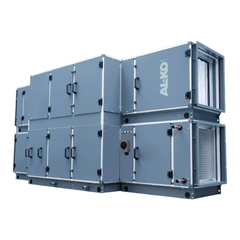
AL-KO HYDROOPT M User manual

TRANSLATION OF THE ORIGINAL INSTALLATION AND OPERATING INSTRUCTIONS
HYDROOPT M ®
CENTRAL VENTILATION AND AIR CONDITIONING UNITS
EN

Translation of the original installation and operating instructions
2
AL-KO HYDROOPT®
Legal
AL-KO THERM GmbH
Hauptstraße 248 - 250
89343 Jettingen-Scheppach
Germany
Telephone: +49 8225 39 - 0
Fax: +49 8225 39 - 2113
E-mail: [email protected]
Revision history
Version Description Date
1.0 Initial release 27/04/2020

Subject to changes in line with technical progress. 3
3061955
Table of contents
1 Product description ........................................................................................4
1.1 Intended use...............................................................................................................................................5
1.2 Possible misuse .........................................................................................................................................5
1.3 Residual dangers........................................................................................................................................5
1.4 Explanation of symbols ..............................................................................................................................5
1.5 Description of various application areas and versions................................................................................6
1.5.1 Station structure (example)........................................................................................................................6
1.5.2 Technical data............................................................................................................................................. 6
1.5.3 Schematic with one exhaust air device (example) ......................................................................................8
1.5.4 Schematic with one exhaust air device and feed option (example).............................................................9
1.6 Delivery ....................................................................................................................................................10
1.7 Transport and storage ..............................................................................................................................10
1.8 Owner's obligations..................................................................................................................................10
1.9 Disposal of the packaging.........................................................................................................................10
2 Installation ................................................................................................ 11
2.1 General information..................................................................................................................................11
2.2 Setup........................................................................................................................................................11
2.3 Filling and venting ....................................................................................................................................12
2.4 Electrical connection.................................................................................................................................12
2.4.1 Cabling to the customer's control technology ..........................................................................................12
2.4.2 Bus model assembly (option)...................................................................................................................13
3 Commissioning........................................................................................... 14
3.1 General information..................................................................................................................................14
3.2 Requirements ...........................................................................................................................................14
3.3 Procedure for commissioning ..................................................................................................................14
3.4 Control-oriented integration of the HYDROOPT M®in the customer's instrument and control facilities ..15
4 Operation.................................................................................................. 16
4.1 Operating unit...........................................................................................................................................16
4.2 Alarm message/Warning message ...........................................................................................................16
4.3 Display menu............................................................................................................................................17
4.4 Main menu (Info key) ...............................................................................................................................19
4.4.1 Password menu........................................................................................................................................19
4.4.2 Settings ....................................................................................................................................................20
4.4.3 Commissioning menu...............................................................................................................................20
4.4.4 System information ..................................................................................................................................21
4.4.5 System integrator.....................................................................................................................................21
4.5 Further operating options .........................................................................................................................26
4.5.1 HMI Web ..................................................................................................................................................26
4.5.2 System graphic (optional) ........................................................................................................................28
5 Warnings, faults and emergencies.................................................................... 29
6 Maintenance .............................................................................................. 30
6.1 Maintenance schedule ..............................................................................................................................31
7 Shut-down................................................................................................. 33
7.1 Decommissioning.....................................................................................................................................33
7.2 Dismantling ..............................................................................................................................................33
7.3 Disposal....................................................................................................................................................33
8 Appendix................................................................................................... 34
8.1 Commissioning list...................................................................................................................................34
Table of contents

Translation of the original installation and operating instructions
4
AL-KO HYDROOPT®
1 Product description
The hydraulic station is used for highly efcient heat and cold recovery in closed-cycle systems.
In winter, heat is extracted from the exhaust air ow from an exhaust air unit and transferred to a heat exchanger in the
central supply air unit.
The integrated controller monitors the operating conditions and regulates the optimum brine circulation amount. Frost
on the exhaust air heat exchanger and freezing of an optional heat feed are prevented by the control system.
Power control is achieved by a frequency-controlled pump and a power regulating valve.
The brine circulation amount is continuously recorded and can be used together with the temperature measurement for
heat quantity metering.
The decision whether heat recovery is possible and how much heat should be recovered must be made by a higher-level
building control technology.
Together with the building control technology, the station thus makes a signicant contribution to saving energy and
reducing operating costs.
Optional components for extended use are:
Plate heat exchanger for heat feed
Plate heat exchanger for cold feed
Redundancy pump for increased operational safety
Warnings and faults are displayed and forwarded via potential-free contacts.
The control system can be easily integrated into higher-level systems via permanently congured bus systems: Modbus,
Bacnet/TCP-IP are available.
Our products are subject to continuous quality control, and comply with the applicable regulations.

Subject to changes in line with technical progress. 5
3061955
Product description
1.1 Intended use
These devices are used exclusively for heat recovery from the exhaust air ow of a central ventilation unit. It may only be
operated within a pressure range of 4–6bar. Deviating operating areas must be agreed with the manufacturer.
1.2 Possible misuse
HYDROOPT M® may only be operated within the scope of the technical data specied by AL-KO. Any other use or use
beyond that described in the "intended use" point is regarded as not in accordance with the designated use. The manu-
facturer cannot be held liable for damage resulting from this.
1.3 Residual dangers
The system may present a danger if it is not operated by trained personnel and/or is not used according to its designated
use.
Residual dangers are potential dangers that are not obviously apparent, such as:
Injury caused by non-observance of the safety instructions
Injury caused by uncoordinated work
Danger caused by working on the electrical system, cables and connections
Please use suitable personal protective equipment such as gloves and safety shoes when working on the device.
1.4 Explanation of symbols
Warning!
This symbol indicates safety measures that must be complied with in order to avoid injury to personnel.
Important!
This symbol indicates safety measures that must be observed under all circumstances to avoid damage to
property.
Special instructions for ease of understanding and handling.

Translation of the original installation and operating instructions
6
AL-KO HYDROOPT®
1.5 Description of various application areas and versions
1.5.1 Station structure (example)
Traggestell
Schaltschrank
Durchflussmesser
Frequenzumrichter
Temperatursensor
Vorlauf
Manometer
Füllen / Entleeren
Wanne
Pum
p
e
Niveauaus
g
leich
Manometer / elektrische
Systemüberwachung
Schmutzfänger
Leistungsregelventil
Frostschutzventil
(Option)
Temperatursensor
Rücklauf
vom Ablufttauscher
zum Ablufttauscher
vom Zulufttauscher
zum Zulufttauscher
1.5.2 Technical data
The station is available in 5 sizes depending on the required quantity of brine being circulated:
(see drawing)
System pressure: 4 to 6bar
Supply voltage: 3Ph/400V/50Hz
Fuse, max.: 20A slow blow
The maximum customer-side back-up fuse is specied on the enclosed circuit diagram.
The exact dimensioning of the pump and the calculation of the necessary system pressure is carried out by AL-KO
THERM after the order is placed.
from the supply air exchanger
to the supply air exchanger
Supporting frame
Switch cabinet
Flowmeter
Frequency converter
(second frequency converter,
optional)
Pressure gauge
Flow temperature sensor
Fill/Empty
Tray
Level compensation
Pump
(second pump, optional)
Pressure gauge/electrical system
monitoring
Power control valve
Frost valve
Dirt trap
Return temperature
sensor
from the exhaust air exchanger
to the exhaust air exchanger

Subject to changes in line with technical progress. 7
3061955
Product description
Dimensions:
Breite Länge
Höhe
Compact control units
Type Dimension Flow ratem3/h Lengthmm Widthmm Heightmm Weightkg
2 DN 32 0.5–1.9 1330 695 1680 170
5 DN 40 2.0–4.9 1330 695 1680 178
10 DN 50 5.0–9.9 1330 695 1680 205
15 DN 65 10.0–14.9 1630 895 1880 307
25 DN 80 15.0–25.0 1630 895 1880 380
Weight varies depending on equipment and pump size.
Width Length
Height

Translation of the original installation and operating instructions
8
AL-KO HYDROOPT®
1.5.3 Schematic with one exhaust air device (example)
M
I
D
P
K
P
P
T
AL-KO -HYDRO-OPT
1
2
35
6
9
7
8
710
11
12
13
4
T11
Mains supply 400V/50Hz 20A
Input for ext. release
HRO demand (0–10V)
Heat-up mode demand (disconnect all exhaust air exchangers)
Operating feedback message (digital out)
Error alarm A
Error alarm B
OPTIONAL bus connection
1 Switch cabinet 9 Expansion tank installation on the intake side
2 Frequency converter 10 Flowmeter
3 Dirt trap 11 Temperature sensor
4 Power control valve 12 Frost valve
5Safety valve 6bar 13 Eff. pressure fan differential pressure sensor
6 Filling connection
7 Pressure gauge
8 Pressure monitor

Subject to changes in line with technical progress. 9
3061955
Product description
1.5.4 Schematic with one exhaust air device and feed option (example)
M
I
D
P
K
P
P
T
AL-KO -HYDRO-OPT
T
1
2
35
6
9
7
8
710
11
T11
11
12
14
15
13
4
Mains supply 400V/50Hz 20A
Input for ext. release
HRO demand (0–10V)
Heat-up mode demand (disconnect all exhaust air exchangers)
Operating feedback message (digital out)
Error alarm A
Error alarm B
OPTIONAL bus connection
1 Switch cabinet 9 Expansion tank installation on the intake side
2 Frequency converter 10 Flowmeter
3 Dirt trap 11 Temperature sensor
4 Power control valve 12 Frost valve
5Safety valve 6bar 13 Eff. pressure fan differential pressure sensor
6 Filling connection 14 Plate heat exchanger, heat feed
7 Pressure gauge 15 Plate heat exchanger, cold feed
8 Pressure monitor

Translation of the original installation and operating instructions
10
AL-KO HYDROOPT®
1.6 Delivery
The station is delivered on a one-way pallet.
1.7 Transport and storage
Transport within the building can be performed by a lift truck or a forklift. The forks can be inserted under the cross
proles of the supporting frame.
Note that the position of the centre of gravity is not exactly central.
The HYDROOPT M®station must be transported upright and secured against tipping over.
Suitable fork lengths must be used to prevent damaging the device.
Use suitable intermediate layer pads to avoid damage to the paint.
The station must be stored in a dry location, protected against the weather. The functional units must be protected
against debris (e.g swarf, stones, wires, etc.) and strong UV exposure. The HYDROOPT M®station is delivered un-
lled and thus frost-proof.
When transporting under difcult conditions (e.g. on open vehicles, under unusual vibrational stresses, transport
by sea or in tropical/subtropical countries), additional packaging must be used that will protect against these par-
ticular inuences.
Constant and, above all, abrupt temperature changes must be prevented during storage. This is especially harmful
if moisture is able to form condensation.
Damage that results from improper packaging, storage, and transport are at the expense of the person responsible.
No personnel may be in the transport area.
All relevant provisions related to occupational safety and environmental protection must be followed during trans-
port.
Sufcient visibility must be maintained during transport.
When using transport devices requiring a driving licence, ensure that the personnel has a valid driving licence.
The HYDROOPT M® station may only be transported by properly trained and qualied personnel who are also famil-
iar with the information in the "Safety" section.
1.8 Owner's obligations
The owner of AL-KO THERM products must regularly train its personnel in the following subjects:
Compliance with and use of the installation and operating instructions as well as statutory regulations.
Intended use of the HYDROOPT M®
If necessary, comply with the instructions for plant protection and the owner's company instructions.
What to do in an emergency.
1.9 Disposal of the packaging
When disposing of the packaging, comply with the relevant local environmental and recycling regulations in your country
and community that are applicable at the time when the activity is undertaken.

Subject to changes in line with technical progress. 11
3061955
Installation
2 Installation
2.1 General information
All hydraulic components are pre-mounted and piped on the supporting frame. All pipe parts and ttings at risk from
condensation are insulated against cold and steam.
Warning!
Assembly, electrical connection, supply connection, maintenance, commissioning and repair, etc. must only be
carried out by trained and authorised specialists.
2.2 Setup
Important!
Components that come loose during transport can lead to faults or damage.
The station must be checked for transport damage upon delivery.
The condition of the ground must be taken into account.
The station should be vertical, the level can be adjusted by the height-adjustable feet.
The station must be bolted to the oor at the feet in a vibration-decoupled manner.
Connect piping to the heat exchangers.
Make sure that no impurities get into the system.
Take into account the reverse ow principle.
Once the piping is complete, the system must be ushed out.
1 Air inlet
2 Air outlet
3 Media inlet
4 Media outlet
Fig.: Reverse ow principle

Translation of the original installation and operating instructions
12
AL-KO HYDROOPT®
2.3 Filling and venting
The lling and venting equipment for the heat exchanger must be set up on-site.
The pipe system must be resistant to ethylene glycol (N).
The glycol content must be prepared according to the manufacturer's instructions.
Note: The glycol mixture must be renewed after a certain elapsed time according to the manufacturer's instructions.
The glycol/water mixture must already be mixed before lling. Otherwise, subsequent mixing is not guaranteed.
Feed and return ow lines must be connected according to professional standards and properly insulated.
The complete piping system must be checked for leak-tightness.
When setting up the heat recovery system, the manufacturer's information regarding the heat carrier used (brine)
must be taken into account.
To protect drinking water, avoid the discharge of heat transfer uid into watercourses. Discharge into wastewater
must be coordinated with the regional disposal company.
2.4 Electrical connection
Make sure that the components and the connection cable at the setup location cannot be either damaged or con-
taminated by oil or other materials.
Check fuses, clamping connections, contactors, and circuit boards to ensure that they are seated rmly.
Re-secure any loose components.
Protect the pump motor against overload.
The electrical connection must be made according to the circuit diagram provided.
Warning!
The electrical connection may only be performed by a certied electrician according to statutory regulations as
well as the guidelines of the local utility company. Perform the connection according to the wiring diagram and
according to the assignment plan.
2.4.1 Cabling to the customer's control technology
The following cabling is required along with the 3-phase supply:
Coming from the customer’s building control technology:
Enable signal potential-free contact
Power control signal 0–10Volt analogue signal
Air volume-proportional signal 4–20mA analogue signal usually from the supply pressure transmitter**
Demand for heating operation * potential-free contact
Outgoing to the customer's building control technology:
Heat recovery operating message potential-free contact
Heat recovery warning message potential-free contact
Heat recovery fault message potential-free contact
* only optional for systems with heat input via plate heat exchanger
** mounted on the ventilation device or enclosed loose
The cabling of the control lines is connected to the terminal rows in the station switch cabinet.

Subject to changes in line with technical progress. 13
3061955
Installation
2.4.2 Bus model assembly (option)
As an option, the control system can be integrated in a superordinate network.
The following bus modules are optionally available for this:
Modbus
BACnet, TCP/IP
The gure shows the Climatix BACnet/POL908.00 IP module/STD. It is connected to the Climatix control system
via the internal communication expansion bus. This takes place via a plug connection on the left side of the control
system.
For data point lists, see "Data point lists appendix".
Please also refer to the introductory manuals of Climatix™.

Translation of the original installation and operating instructions
14
AL-KO HYDROOPT®
3 Commissioning
3.1 General information
Warning!
Installation, commissioning, maintenance, and repair work may only be performed by trained and qualied
specialist personnel.
3.2 Requirements
For commissioning the HYDROOPT M®station, the following actions must already have been completed on site:
The supply and exhaust air system must be operational.
The air quantities must have already been measured.
The glycol content of the system must already have been determined.
The system pressure must correspond to the specied idle pressure.
All isolation devices on the station and any on the heat exchangers must be open.
The electrical supply of the station must have been checked.. The protective earth conductor and neutral conductor
in particular must be in place.
Important!
The rotary pump must have been vented according to the manufacturer's instructions. For this purpose,
the corresponding plugs must be opened until brine ows out free of bubbles. Please have a suitable
collection container available for this procedure.
Improper venting can cause damage to the rotary pump.
3.3 Procedure for commissioning
After turning on the main switch, the pump can be manually operated on the frequency converter for a brief time.
The direction of rotation must be checked. The corresponding directional arrow is marked on the pump.
The analogue pressure monitor attached upstream of the pump protects the pump from running dry due to lost
brine. The switching threshold was set in the factory to approx. 1.5bar (warning) and to 0.5bar media overpres-
sure (fault).
Finally, reset the frequency converter to AUTOmatic operation.
The pressure transmitter attached to the supply air device must be connected to the inlet nozzle and the device ring
line on the intake side. The pressure transmitter must be set to 4–20mA.
The measuring range (factory setting 2500Pa) may have to be adapted.
The pressure transmitter measures the differential pressure at the inlet nozzle and outputs this pressure linearly (not
square root).
The measuring range end value of the owmeter is set to approx. 1.4x the nominal uid volume at the factory, as the
uid volume is raised above the nominal uid volume even for a short time if there is a risk of frost.
Give the customer's enable signal and bring the customer's power control signal to 10volts.
From 95%, the controller display will show the request "Optimizing active” unless other operating states (e.g.
defrost) are active. The uid volume is then optimised on the basis of the supply air quantity.
1m3/h brine corresponds to about 3300m3/h air.
This optimisation process can take several minutes.
If the power control signal is set to below 90% (9volts), this initially reduces the pump speed. If this reaches a
lower limit of 12Hz, the brine is also directed past the exhaust air heat exchanger via the power control valve (by-
pass operation).

Subject to changes in line with technical progress. 15
3061955
Commissioning
3.4 Control-oriented integration of the HYDROOPT M®in the customer's instrument and control
facilities
The closed-cycle system covers the majority of the heat output during operation by recovering heat from the exhaust
air ow.
Due to the inertia of the system, any existing pump hot water heater (PWW) must be rinsed before starting the central
ventilation system.
After a rinsing period to warm up the on-site pipeline system, the air shut-off dampers must be opened.
Only then may the fans be put into operation and the enable given for the closed-cycle system.
After the enable contact, an analogue request signal (0–10 Volt) is required by the customer for operation of the
closed-cycle system. The heat recovery output can be controlled proportionally from 0–100% via the signal.
Thus the complete station behaves like a (albeit sluggish) heating valve with a continuous valve drive and can be easily
integrated in the customer's control strategy.
The decision whether the heat recovery can take place must be made by the customer's control system by comparing
the air temperature.
y
100
%
y1 WRG
y2 Heizen
Wärmebedarf
WRG
Heizen
Fig. Control strategy for controlling the HYDROOPT M®closed-cycle system
HRO
Heating
Heating requirement
y1 HRO
y2 Heating

Translation of the original installation and operating instructions
16
AL-KO HYDROOPT®
4 Operation
4.1 Operating unit
The operation is menu-driven and is carried out via the keys on the control unit or an optional remote control panel.
No. Designation General function
1 INFO button with integrated
LED
This button can be used to navigate from any menu item to the main menu.
2 ALARM button with integrated
LED
This button can be used to navigate from any menu item to the alarms. The inte-
grated LED also indicates the alarm and acknowledgement status (see chapter “5
Warnings, faults and emergencies” on page 29).
3 ESC button This button can be used to exit the currently displayed menu item.
4 UP button This button can be used to scroll up in the current menu or to increase the setting
value.
5 DOWN button This button can be used to scroll down in the current menu or to reduce the setting
value.
6 ENTER button This button can be used to conrm a new setting and activate the new setting value.
7 Line The number of the line that is currently marked is shown here. The number after the
slash indicates the total number of lines on this page.
8 Page The name of the page on which you are located is shown here.
4.2 Alarm message/Warning message
The actions and status displays for the arrival, acknowledgement and resetting of an alarm are listed below:
Each alarm is indicated by the alarm LED ashing red.
By pressing the Alarm key, the alarm is displayed in plain text including alarm class, date and time.
Each new alarm generates a line in the alarm list as well as in the alarm history. The alarm history is displayed by
pressing the Alarm key several times.
An acknowledged but still active alarm is present when the alarm LED on the control panel on the switch cabinet
lights up constantly.

Subject to changes in line with technical progress. 17
3061955
Operation
Reset alarms:
Alarm list: The line is deleted.
Alarm history: Display as an "outgoing" alarm
Alarm types:
The following table describes all of the alarms that can be displayed. Class B does not lead to a shut-down, but merely
serves as a warning.
Alarm text Class Description/Remedy
Feed temp. A Sensor defective or cable break -> Sensor check
required
Return temp. A Sensor defective or cable break -> Sensor check
required
Feed temp. after feed-in A Sensor defective or cable break -> Sensor check
required
Eff. pressure1 A Sensor defective or cable break -> Sensor check
required
Eff. pressure2 A Sensor defective or cable break -> Sensor check
required
Fluid volume B Fluid volume implausible
The brine circulation is checked within a dened
period of time. If the uid volume is implausible, the
system is switched off with an A alarm
Pump1 B Pump frequency converter has triggered -> System
check required
Pump2 B Pump frequency converter has triggered -> System
check required
Pump1 and pump2 A If both pumps have a fault, the system switches off
Pump frequency converter is faulty -> System
check required
Sole pressure warning B Pressure sensor reports lack of system pressure ->
System check required
Sole pressure fault A Pressure sensor reports lack of system pressure ->
System check required
Class A alarms lead to system shut-down.
4.3 Display menu
The screens that are not described must be skipped with the Enter key when they appear.
The Start menu visualises the current status with symbols in the top line. The digital enable is shown in "Ext. Demand"
and the analogue request signal in "Demand". The Optimizing display indicates whether or not the optimisation is active.
If the higher-level controller does not enable it, "Off" appears in the main menu.

Translation of the original installation and operating instructions
18
AL-KO HYDROOPT®
In the main menu, the access level can be logged in, settings adjusted and system information retrieved.
The displayed language can be changed with the service password in the main menu.
System information, e.g. temperatures and brine/air volumes, can be viewed in the main menu under Information. These
can vary depending on the expansion stage.
Information about energy volumes can be found under the "Energy volume" menu item.

Subject to changes in line with technical progress. 19
3061955
Operation
4.4 Main menu (Info key)
The selection of menu items changes depending on the access level:
Password input
Information
Settings
Versions
The display of the screens depends on the system conguration. Only the screens required for the system conguration
are displayed.
4.4.1 Password menu
Access rights are delivered from the factory as follows:
Level Default password Description
User 1000 Level for the operator to select the setpoint source and
alarm acknowledgement
Service **** Level for service technicians with many parameter
settings
Factory **** Manufacturer level for xed parameters that are set in
the factory
The password can be changed in the corresponding access level.
Example:
If the factory user password is entered in password input, a key symbol appears at the top right of the control unit as an
indicator of the "User" access level. Two keys are displayed when the service password is entered.

Translation of the original installation and operating instructions
20
AL-KO HYDROOPT®
4.4.2 Settings
The setting options vary depending on the expansion stage. The date and time can be changed with the user password.
All other settings fall under service applications.
Under Settings, the service technician can adjust the system parameters in the service level.
Always set a valid date or the correct time in order to obtain all functions.
4.4.3 Commissioning menu
Warning!
The safety functions of the software can be deactivated if incorrect settings are made.
Commissioning can only be achieved by entering the service password.
During commissioning, measurement and control signals can be checked for plausibility with the service password.
Table of contents
Other AL-KO Fan manuals
Popular Fan manuals by other brands

Hunter
Hunter B Owner's guide and installation manual

Lasko
Lasko T48311 Important instructions & operating manual

Modern Forms
Modern Forms VOX FLUSH Series installation instructions

Bestron
Bestron DFT35Z instruction manual

Kichler Lighting
Kichler Lighting Kimberley instruction manual

Tool Shed
Tool Shed TSVE8 quick start guide