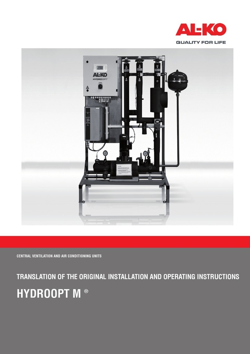
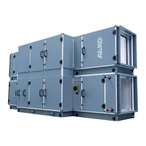
AL-KO AT4F Series User manual

Page
Page
Ed.
Original
EPLAN
FL +
Date
Date
Replaced by
Title page / cover sheet
1
Modification
0 76
Appr
Replacement of
8 93
49
2
4
24.01.2020
1
2
=
Name
5
1/
&BAA
3222370 1
Stadion Arcul de Triumf
Pos.
Version 2019.1
Project designation
3222370
Stadion Arcul de Triumf
Order no :
:
Hauptstraße 248-250
89343 Jettingen-Scheppach
Germany
Phone: 00498225/39-0
AL-KO THERM GMBH electrical documentation
49
23Number of circuit diagram pages:
Total number of pages:
Item number 1:
Device type : AT4F

Page
Page
Ed.
1
Original
EPLAN
FL +
Date
Date
Replaced by
Title page / cover sheet
1
Modification
0 76
Appr
Replacement of
8 93
49
&BAB/3
4
24.01.2020
2
2
=
Name
5
2/
&BAA
3222370 1
Stadion Arcul de Triumf
Pos.
Version 2019.1
Power consumption
Dimensions
protection typ
H800 W600 mm
pre-fuse
24.77 A
main circuits
wiring colors
Neutral
protective conductor
:
:
:
:
Control circuits >48V/AC :
Control circuits <48V/AC
Control circuits 24V/DC
Signal lines (Ω, V, A)
communication lines
external voltage
:
:
:
:
IP 54
:
Control voltage(s)
information
Used standards/directives
Cabinet
Technical data
:
:
:
:
Operating voltage
Rated current
17.16 kW
SCCR
:
:
:
minimum cross-sections
terminal blocks
Comments / Special
IEC 60204 part 1
network configuration :
35 A
6 kA
PEN conductor :
main circuits :
control circuits :
Signal lines (Ω, V, A) :
-X0 :
-X1 :
-X2 :
-X3 :
-X4 :
-X5 :
-X6 :
-X7 :
-X8 :
-X9 :
protection class :
:
3~ 400V/AC 50 Hz
TN-S
24V/AC
I (protective conductor)
Incoming supply
400V - power
230V - power
SSp1 - signal
potential free
external voltage
fieldbus
BCS-Bus
process bus
SSp2 - signal
SSp-minus - distribution
1,5 mm²
1 mm²
1 mm²
BK black
(L)BU light blue
GNYE green/yellow
GNYE green/yellow
RD red
BN brown
(D)BU dark blue
GY grey
WH/BN white-brown twisted
OG orange
-XD1
:
heating/ventilation
-XD2
:SSp-plus- distribution
-XD3
-XD4 :
SSp-plus DDC- distribution
Door hinge : right
cable entry : bottom
Control voltage(s) : 4 - 10mm²

Page
Page
Ed.
&BAA/2
Original
EPLAN
FL +
Date
Date
Replaced by
Table of contents
1
Modification
0 76
Appr
Replacement of
8 93
49
4
4
24.01.2020
3
2
=
Name
5
3/
&BAB Table of contents
3222370 1
Stadion Arcul de Triumf
Pos.
Version 2019.1
Edited by
Table of contents
DatePage descriptionPage Page Page
Title page / cover sheet 24.01.20201
Title page / cover sheet 24.01.20202
Table of contents 24.01.20203
Table of contents 24.01.20204
PnID MCR schematic 24.01.20205
Incoming supply 24.01.2020=ESP 6
N-Distribution 24.01.2020=ESP 7
PE-distribution 24.01.2020=ESP 8
Control cabinet accessories 24.01.2020=SZU 9
control voltage AC 24.01.2020=SSP 10
Plus distribution AC 24.01.2020=SSP 11
Minus Distribution AC 24.01.2020=SSP 12
Controller 24.01.2020=REG 13
Expantion module 1 24.01.2020=REG 14
Controller occupancy 24.01.2020=REG 15
Controller occupancy expansion module 1 24.01.2020=REG 16
branch Process bus 24.01.2020=REG 17
GA-connection 24.01.2020=GLT 18
Temperature sensors 24.01.2020=TPS 19
CO2 Sensor 24.01.2020=LQS 20
Sensor technology filter 24.01.2020=FIL 21
pressure transmitter 24.01.2020=DRK 22
fold/connection point 24.01.2020=ASK 23
WRG-control 24.01.2020=WRG 24
supply air fan 1 24.01.2020=VTL1 25
exhaust air fan 1 24.01.2020=VTL2 26
pump hot water coil 1 24.01.2020=PWW1 27
heating pump 24.01.2020=WP 28
Terminal diagram X1 24.01.202029
Terminal diagram X2 24.01.202030
Terminal diagram X3 24.01.202031
Terminal diagram X3 24.01.202032
Terminal diagram X3 24.01.202033
FL
FL
FL
FL
FL
FL
FL
FL
FL
FL
FL
FL
FL
FL
FL
FL
FL
FL
FL
FL
FL
FL
FL
FL
FL
FL
FL
FL
FL
FL
FL
FL
FL

Page
Page
Ed.
3
Original
EPLAN
FL +
Date
Date
Replaced by
Table of contents
1
Modification
0 76
Appr
Replacement of
8 93
49
&EFB/5
4
24.01.2020
4
2
=
Name
5
4/
&BAB Table of contents
3222370 1
Stadion Arcul de Triumf
Pos.
Version 2019.1
Edited by
Table of contents
DatePage descriptionPage Page Page
Terminal diagram X3 24.01.202034
Terminal diagram X3 24.01.202035
Terminal diagram X3 24.01.202036
Terminal diagram X4 24.01.202037
Terminal diagram X5 24.01.202038
Terminal diagram X8 24.01.202039
Terminal diagram X0 24.01.202040
Terminal diagram XD1 24.01.202041
Terminal diagram XD2 24.01.202042
Terminal diagram XD3 24.01.202043
Terminal diagram XD4 24.01.202044
Terminal diagram XE1 24.01.202045
Terminal diagram XE2 24.01.202046
Terminal diagram XPE 24.01.202047
Terminal diagram X3 24.01.202048
FL
FL
FL
FL
FL
FL
FL
FL
FL
FL
FL
FL
FL
FL
FL
Cable overview W1 - W36 24.01.202048 FL

Page
Page
Ed.
&BAB/4
Original
EPLAN
FL +
Date
Date
Replaced by
PnID MCR schematic
1
Modification
0 76
Appr
Replacement of
8 93
49
&EFS=ESP/6
4
24.01.2020
5
2
=
Name
5
5/
&EFB
3222370 1
Stadion Arcul de Triumf
Pos.
Version 2019.1
EHA
ODA
SUP
ETA
ART Tech II
controller
DO
AI
AO
DI
BUS
Room
X1 X3
T
further requirements:
BSK:
Smoke detector:
---
---
T
X14
Q11
M
ΔP
Y12
M
X4
T
X7
Q3
FC/EC
X15
ΔP ΔP
BMS
X18D1 D3
Q5 Q6Q14
Y1
D2
T
X2
T
D4
ΔP
Q4
X8
X6
FC/EC
X16
ΔP
Q12
M
T
M

Page
Page
Ed.
&EFB=/5
Original
EPLAN
FL +
Date
Date
Replaced by
ESP
Incoming supply
1
Modification
0 76
Appr
Replacement of
8 93
49
7
4
24.01.2020
6
2
=
Name
5
6/
Incoming supply
&EFS wiring diagram
3222370 1
Stadion Arcul de Triumf
Pos.
Version 2019.1
building:
room:
distributor:
fuse:
Incoming supply
Note: When using a FI, this must be observed, that this is
an all-current sensitive FI switch!!
-A1
PEN
-W1
-X0
4 - 10mm²
L1 L2 L3
2
1
4
3
6
5
-Q1
32 A
L1 / =SSP/10.0
L2 / =SSP/10.0
L3 / =SSP/10.0
N/ 7.0
PE / 8.0
L1_VHS / =SZU/9.0
L1 L2 L3 N PE

Page
Page
Ed.
6
Original
EPLAN
FL +
Date
Date
Replaced by
ESP
N-Distribution
1
Modification
0 76
Appr
Replacement of
8 93
49
8
4
24.01.2020
7
2
=
Name
5
7/
Incoming supply
&EFS wiring diagram
3222370 1
Stadion Arcul de Triumf
Pos.
Version 2019.1
N1
-XE1
N2
N3
N
/6.2
N_2 / =SZU/9.1
N_3 / =WP/28.0
N_4 /
N_5 /
N_6 /
N_7 /
N_8 /
N_9 /
N_10 /
N_11 /
N_1 / =SSP/10.0

Page
Page
Ed.
7
Original
EPLAN
FL +
Date
Date
Replaced by
ESP
PE-distribution
1
Modification
0 76
Appr
Replacement of
8 93
49
=SZU/9
4
24.01.2020
8
2
=
Name
5
8/
Incoming supply
&EFS wiring diagram
3222370 1
Stadion Arcul de Triumf
Pos.
Version 2019.1
ground connection
mounting plate
ground connection
housing
ground connection
door
PE
-UR1
PE
-UC1
PE
-UC2
PE1
-XE2
PE2
PE3
PE
/6.2
PE_5 / =SSP/10.0
PE_6 / =SZU/9.2
PE_7 / =SZU/9.3
PE_8 / =SSP/10.0
PE_9 /
PE_10 /
PE_11 /
PE_12 /

Page
Page
Ed.
=ESP/8
Original
EPLAN
FL +
Date
Date
Replaced by
SZU
Control cabinet accessories
1
Modification
0 76
Appr
Replacement of
8 93
49
=SSP/10
4
24.01.2020
9
2
=
Name
5
9/
Control cabinet accessories
&EFS wiring diagram
3222370 1
Stadion Arcul de Triumf
Pos.
Version 2019.1
RLT-device
Distribution box
power outlet
NSGAFÖU
L NPE
-XDE
I Δ
-F1
25A
30mA
1
2
3
4
Enclosure light
1
2
-F2
B10
6kA
3x1,5
NYM-J
-W2
BN BU GNYE
-XE1
L N PE
-X2 1 2 PE
2
-XD4
1
-XD4
4
-XD4
3
-XD4
L
N
PE
-E1
12 W
230 V/AC
L1_VHS
/=ESP/6.2
N_2 / =ESP/7.2
PE_6 / =ESP/8.2
PE_7 / =ESP/8.2

Page
Page
Ed.
=SZU/9
Original
EPLAN
FL +
Date
Date
Replaced by
SSP
control voltage AC
1
Modification
0 76
Appr
Replacement of
8 93
49
11
4
24.01.2020
10
2
=
Name
5
10 /
Control voltage
&EFS wiring diagram
3222370 1
Stadion Arcul de Triumf
Pos.
Version 2019.1
If the auxiliary circuit
is operated without
grounding, insulation monitoring
must be installed.
2
6
1
5
PE
-TA1
prim. 230V/AC
sec. 24V/AC
100VA
L1/1
T1/2
L2/3
T2/4
L3/5
T3/6
-FC1
0,45 - 0,63 A
Set 0,45 A I> I>
I>
1
2
-F3
C4A
-XPE
1
1
2
-FC2
C4A
L1 / =VTL1/25.0
L2 / =VTL1/25.0
L3 / =VTL1/25.0
L1
/=ESP/6.9
L2
/=ESP/6.9
L3
/=ESP/6.9
L24
/11.0
N24
/12.0
N_1
/=ESP/7.2
PE_5
/=ESP/8.2
PE_8
/=ESP/8.2
L24_Ctrl
/11.0

Page
Page
Ed.
10
Original
EPLAN
FL +
Date
Date
Replaced by
SSP
Plus distribution AC
1
Modification
0 76
Appr
Replacement of
8 93
49
12
4
24.01.2020
11
2
=
Name
5
11 /
Control voltage
&EFS wiring diagram
3222370 1
Stadion Arcul de Triumf
Pos.
Version 2019.1
24V/AC plus distribution
control cabinet
Field devices 24VAC
Controller
2
3
1
-XD3
1
-XD2
L24_2 / =GLT/18.0
L24_3 / =ASK/23.1
L24_4 / =ASK/23.3
L24_6 /
L24_5 / =WP/28.2
L24_8 /
L24_10 /
L24_9 /
L24_7 /
L24_11 /
L24
/10.2
L24_12 /
L24_1 / =REG/13.3
L24_Ctrl
/10.2

Page
Page
Ed.
11
Original
EPLAN
FL +
Date
Date
Replaced by
SSP
Minus Distribution AC
1
Modification
0 76
Appr
Replacement of
8 93
49
=REG/13
4
24.01.2020
12
2
=
Name
5
12 /
Control voltage
&EFS wiring diagram
3222370 1
Stadion Arcul de Triumf
Pos.
Version 2019.1
24V/AC minus distribution
control cabinet
1
-XD1
2
3
N24_3 / =WP/28.2
N24_4 /
N24_2 / =GLT/18.0
N24_7 /
N24_5 /
N24_6 /
N24_8 /
N24_9 /
N24_10 /
N24_11 /
N24
/10.1 N24_1 / =REG/13.2

Page
Page
Ed.
=SSP/12
Original
EPLAN
FL +
Date
Date
Replaced by
REG
Controller
1
Modification
0 76
Appr
Replacement of
8 93
49
14
4
24.01.2020
13
2
=
Name
5
13 /
Controller
&EFS wiring diagram
3222370 1
Stadion Arcul de Triumf
Pos.
Version 2019.1
PB
Siemens Climatix 638.00
Controller
RS485 USB
T1
T8 T9
Siemens
POL871.72
DDC-control unit
process bus distribution
control cabinet
-K0
T-HI
1
CE-
2
CE+
1
REF
2
B-
3
A+
T-SV
20V
124V
T-IP
-PZ1
8x24AWG
Patchkabel
-W3
1,0
WH
1,0
BN
L24_1
/=SSP/11.2
N24_1
/=SSP/12.2
IO / 14.3
PB+ / 17.1
PB- / 17.1

Page
Page
Ed.
14
Original
EPLAN
FL +
Date
Date
Replaced by
REG
Controller occupancy
1
Modification
0 76
Appr
Replacement of
8 93
49
16
4
24.01.2020
15
2
=
Name
5
15 /
Controller
&EFS wiring diagram
3222370 1
Stadion Arcul de Triumf
Pos.
Version 2019.1
T2.1
T2.2
T2.3
Universale in-/outputs
T4
Digital inputs
T3
Analog outputs
T6
Relay outputs
T7
-K0
6
X1 =TPS/19.1 outside air temperature
5
M
4
X2 =TPS/19.2 Supply air temperature
3
X3 =TPS/19.3 extract air temperature
2
M
1
X4 =TPS/19.5 exhaust air temperature after HR
6
X5 =TPS/19.6 frost- temperature / heater
5
M
4
X6 =VTL2/26.5 Alarm fan
3
X7 =VTL1/25.6 Signal supply air fan
2
M
1
X8 =VTL2/26.6 Signal extract air fan
2
+24V
1
+24V
-K0
6
D2 =PWW1/27.7 antifreeze/STB heater
5
D3 =GLT/18.3 smoke detector/Fire alarm system
4
M
3
D4 =FIL/21.8 Alarm filter
1
M
8
D1 =GLT/18.1 external enabling
7
M
-K0
1
Y2 =WP/28.5 heat pump signal
3
Y1 =PWW1/27.4 Signal heater
2
M
-K0
2
Q14 =WRG/24.3 enable HR
1
Q13 =WRG/24.3
4
Q24 =PWW1/27.2 enable heater
3
Q23 =PWW1/27.2
6
Q34 =VTL1/25.2 enable supply air Fan
5
Q33 =VTL1/25.2
8
Q44 =VTL2/26.2 enable extract air fan
7
Q43 =VTL2/26.2
2
Q54 =GLT/18.4 operating message
1
Q53 =GLT/18.4
4
Q64 =GLT/18.5 collective fault A-alert
3
Q63 =GLT/18.5
2
D5 =WRG/24.5 Alarm HR

Page
Page
Ed.
15
Original
EPLAN
FL +
Date
Date
Replaced by
REG
Controller occupancy expansion module 1
1
Modification
0 76
Appr
Replacement of
8 93
49
17
4
24.01.2020
16
2
=
Name
5
16 /
Controller
&EFS wiring diagram
3222370 1
Stadion Arcul de Triumf
Pos.
Version 2019.1
T2
Universale in-/outputs
T3
Relay outputs
T4
Relay outputs
T1
Universale in-/outputs
T5
Analog outputs
-K1
1
X5 =DRK/22.1 supply air flow rate (effective)
2
M
3
X6 =DRK/22.3 extract air flow rate (effective)
4
X7 =WP/28.6 heat pump fault
5
M
6
X8 =GLT/18.2 External enabling 2
-K1 -K1
2
Q14 =ASK/23.1 outside air damper
1
Q13
4
Q24 =ASK/23.4 exhaust air damper
3
Q23
6
Q34 =WP/28.3 change-over¶heating-cooling
5
Q33 =WP/28.3
2
Q44 =GLT/18.6 collective fault B-alert
1
Q43 =GLT/18.6
-K1
1
X1 =DRK/22.6 supply air pressure
2
M
3
X2 =DRK/22.8 extract air pressure
4
X3 =LQS/20.2 extract air quality
5
M
6
X4 =TPS/19.7 room temperature
-K1
3
Y2 =WRG/24.6 Signal HR
1
Y1 =ASK/23.6 signal mixed air damper
2
M

Page
Page
Ed.
16
Original
EPLAN
FL +
Date
Date
Replaced by
REG
branch Process bus
1
Modification
0 76
Appr
Replacement of
8 93
49
=GLT/18
4
24.01.2020
17
2
=
Name
5
17 /
Controller
&EFS wiring diagram
3222370 1
Stadion Arcul de Triumf
Pos.
Version 2019.1
process bus process bus
4 PE
GY
Steckbrücke
GY
Steckbrücke
-X8 1 2 -X8 3PE
PB- / 13.3
PB+ / 13.3

Page
Page
Ed.
=REG/17
Original
EPLAN
FL +
Date
Date
Replaced by
GLT
GA-connection
1
Modification
0 76
Appr
Replacement of
8 93
49
=TPS/19
4
24.01.2020
18
2
=
Name
5
18 /
BMS connection
&EFS wiring diagram
3222370 1
Stadion Arcul de Triumf
Pos.
Version 2019.1
external Enabling
(0 = blocked)
potential free
operating message
(1 = operation)
potential free
collective fault
A-alert (1 = fault)
building automation / building control
potential free
collective fault
B-alert (1 = fault)
external enabling 2
(0 = blocked)
Digital input
T4
external enabling
=REG-K0
=REG/15.3
D1
8
Relay output
T7
operating message
=REG-K0
=REG/15.8
Q54 (Q5)
2
Q53
1T7
Relay output
T7
collective fault A-alert
=REG-K0
=REG/15.8
Q64 (Q6)
4
Q63
3T7
Relay output
T4
collective fault B-alert
=REG-K1
=REG/16.8
Q44 (Q14)
2
Q43
1T4
Digital input
T2
External enabling 2
=REG-K1
=REG/16.3
X8 (X18)
6
fire/smoke
(0= fire-/ smoke detector)
Digital input
T4
smoke detector/Fire alarm
system
=REG-K0
=REG/15.3
D3
5
-GLT
3x1
-W6
-X5 3 4
-X5 1 2
3x1
-W7
1 2 1 2
PE PE
GNYE GNYE
PE PE
RD
Steckbrücke
BU
Steckbrücke
RD
Steckbrücke
BU
Steckbrücke
-X3 - +
RD
Steckbrücke
BU
Steckbrücke
+
-
-X3
1
+
-
-X3
2
-X5 5 6
3x1
-W8
1 2 GNYE
PE
PE
2x1
-W4
1 2
RD
Steckbrücke
BU
Steckbrücke
+
3
-
-X3
2x1
-W5
1 2
N24_2 / =TPS/19.0
L24_2 / =TPS/19.0
L24_2 / =SSP/11.2
N24_2 / =SSP/12.2

Page
Page
Ed.
=GLT/18
Original
EPLAN
FL +
Date
Date
Replaced by
TPS
Temperature sensors
1
Modification
0 76
Appr
Replacement of
8 93
49
=LQS/20
4
24.01.2020
19
2
=
Name
5
19 /
Temperature sensors
&EFS wiring diagram
3222370 1
Stadion Arcul de Triumf
Pos.
Version 2019.1
outside air temperature
Universal input
T2.1
outside air temperature
=REG-K0
=REG/15.1
X1
6
Siemens
QAC2030
Supply air temperature
Universal input
T2.1
Supply air temperature
=REG-K0
=REG/15.1
X2
4
Siemens
QAM2130.040
extract air temperature
Universal input
T2.1
extract air temperature
=REG-K0
=REG/15.1
X3
3
Siemens
QAM2130.040
exhaust air temperature after HR
Universal input
T2.1
exhaust air temperature
after HR
=REG-K0
=REG/15.1
X4
1
Siemens
QAM2130.040
frost- temperature / heater
Universal input
T2.2
frost- temperature / heater
=REG-K0
=REG/15.1
X5
6
room temperature
Universal input
T1
room temperature
=REG-K1
=REG/16.1
X4 (X14)
6
Siemens
QAA2030
+
-
-X3
4
BU
Steckbrücke
RD
Steckbrücke
2x1
-W9
1 2
-B1 B M
NTC
+
-
-X3
5
BU
Steckbrücke
RD
Steckbrücke
2x1
-W10
1 2
-B2 B M
NTC
+
-
-X3
6
BU
Steckbrücke
RD
Steckbrücke
2x1
-W11
1 2
-B3 B M
NTC
+
-
-X3
7
BU
Steckbrücke
RD
Steckbrücke
2x1
-W12
1 2
-B4 B M
NTC
+
-
-X3
8
BU
Steckbrücke
RD
Steckbrücke
+
-
-X3
9
BU
Steckbrücke
RD
Steckbrücke
2x1
-W13
1 2
-B5 B M
NTC
N24_2 / =LQS/20.0
L24_2 / =LQS/20.0
N24_2
/=GLT/18.9
L24_2
/=GLT/18.9

Page
Page
Ed.
=TPS/19
Original
EPLAN
FL +
Date
Date
Replaced by
LQS
CO2 Sensor
1
Modification
0 76
Appr
Replacement of
8 93
49
=FIL/21
4
24.01.2020
20
2
=
Name
5
20 /
&EFS wiring diagram
3222370 1
Stadion Arcul de Triumf
Pos.
Version 2019.1
exhaust
air air quality sensor
Universal in-/output
T1
extract air quality
=REG-K1
=REG/16.1
X3 (X13)
4
BU
Steckbrücke
RD
Steckbrücke
+
-
-X3
10
N24_2 / =FIL/21.0
L24_2 / =FIL/21.0
N24_2
/=TPS/19.9
L24_2
/=TPS/19.9
Other manuals for AT4F Series
1
Table of contents
Other AL-KO Fan manuals
Popular Fan manuals by other brands

Hunter
Hunter B Owner's guide and installation manual

Lasko
Lasko T48311 Important instructions & operating manual

Modern Forms
Modern Forms VOX FLUSH Series installation instructions

Bestron
Bestron DFT35Z instruction manual

Kichler Lighting
Kichler Lighting Kimberley instruction manual

Tool Shed
Tool Shed TSVE8 quick start guide