Alamarin Jet AJ 285 User manual

Operation and
maintenance manual


Table of contents
Operation and maintenance manual
KHO/285/EN/1.0.0. iii
Table of contents
1. Introduction .................................................................................................. 1
1.1. Safety precautions ............................................................................. 1
1.2. Symbols ............................................................................................. 1
2. The Jet Propulsion Unit ............................................................................... 3
2.1. Structure ............................................................................................ 3
2.2. Serial number .................................................................................... 4
3. Operation ..................................................................................................... 5
3.1. Starting .............................................................................................. 5
3.2. Steering ............................................................................................. 6
3.3. Controlling ......................................................................................... 7
3.3.1. The positions of the reversing deflector control lever ............. 7
3.3.2. Using the reversing deflector ................................................. 9
3.4. Driving under difficult conditions ..................................................... 9
3.5. Dry running ..................................................................................... 10
4. Maintenance ............................................................................................... 11
4.1. Washing ........................................................................................... 11
4.2. Corrosion protection ........................................................................ 11
4.2.1. Changing the anodes ............................................................ 11
4.2.2. Touch-up painting and antifouling ........................................ 13
4.3. Bearing ............................................................................................ 14
4.3.1. Lubricating the front bearing ............................................... 15
4.3.2. Lubrication of the rear end bearing ..................................... 16
4.4. Control system ................................................................................. 18
4.5. Seals ................................................................................................ 19
4.6. Hydraulic reversing deflector control system ................................. 20
4.7. Raw water cooling ........................................................................... 24
4.8. Impeller ........................................................................................... 24
4.8.1. Checking the impeller ........................................................... 25
4.8.2. Removing the impeller .......................................................... 25
4.8.3. Installing the impeller ........................................................... 29
4.9. Intermediate shaft ........................................................................... 32
5. Problem situations ..................................................................................... 33
5.1. Cavitation ......................................................................................... 33
5.2. Ventilation ........................................................................................ 34
5.3. Clogged jet ...................................................................................... 35
Appendix 1. Declaration of incorporation for partially completed
machinery ....................................................................................................... 39
Appendix 2. Grease recommendations ........................................................... 40
Appendix 3. Oil recommendations ................................................................. 41


Introduction
Operation and maintenance manual
KHO/285/EN/1.0.0. 1
1. Introduction
Congratulations on purchasing your new Alamarin-Jet AJ 285 water jet
propulsion unit!
This manual contains important information on the operation, use and
maintenance of the unit. Please read these instructions carefully before using
the unit. This way the unit will be safe to operate.
Please retain this manual for the duration of the product's life cycle. If you lose
the manual, contact your nearest distributor for a new one. If you sell the unit,
make sure to hand over this manual to the new owner.
Please contact your nearest distributor if you have any queries regarding the
operation or maintenance of the unit.
© Alamarin-Jet Oy
Tuomisentie 16
FI-62300 Härmä, Finland
Telephone: +358 10 7745 260
Fax: +358 10 7745 269
Internet: www.alamarinjet.com
All rights reserved.
The information in this manual may not be copied, published or reproduced in
any way whatsoever, or exploited for commercial purposes, without express
written permission from Alamarin-Jet Oy.
The information in this manual is subject to change without notice. Alamarin-
Jet Oy reserves the right to modify the contents without notice.
1.1.Safety precautions
Read these instructions carefully before you operate a boat equipped with the
water jet propulsion unit or carry out any maintenance procedures. Please
also read the boat's manual. Always follow the instructions and the safety
precautions below.
• Only a person with adequate training is permitted to carry out the
demanding maintenance procedures described in this manual.
• The person carrying out the procedures must always wear the appropriate
protective equipment.
• The work premises must be sufficiently large, safe and well-lit.
• The tools that are to be used must be clean and appropriate for the intended
purpose.
1.2.Symbols
Please refer to table 1 for a description of the symbols used in this manual.
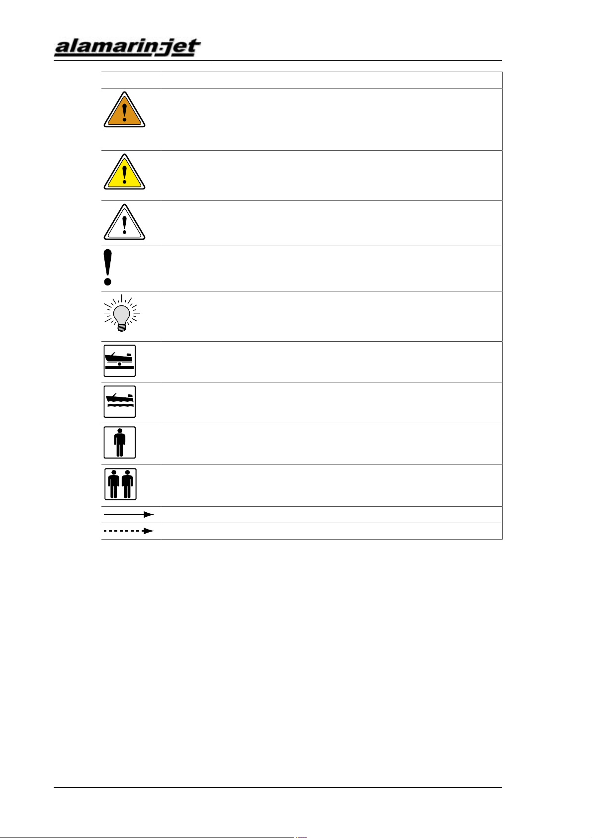
Table 1. The symbols used in the manual
Icon Description
DANGER
Negligence in the performance of a procedure can cause a threat
to your life.
Introduction
Operation and maintenance manual
2 KHO/285/EN/1.0.0.
Icon Description
WARNING
Negligence in the performance of the procedures can lead to
personal injury, breakdown of equipment, or serious malfunction
of the equipment.
CAUTION
The procedure involves minor danger or a possibility of minor
damage to equipment.
WARRANTY
The warranty is voided if the procedure is carried out incorrectly.
NOTE
Important notice or fact.
TIP
Additional information that facilitates the performance of work or
a procedure.
MAINTENANCE ON LAND
The boat must be lifted out of the water for maintenance.
MAINTENANCE IN WATER
The maintenance procedure can be carried out in water.
CARRIED OUT BY ONE PERSON
One person can carry out the procedure.
CARRIED OUT BY TWO PERSONS
Two persons must carry out the procedure.
INDICATOR ARROW
ARROW DESCRIBING MOTION
Please note that this instruction uses the terms "jet" and "jet propulsion unit".
They mainly refer to the same thing.
The Jet Propulsion Unit
Operation and maintenance manual
KHO/285/EN/1.0.0. 3
2. The Jet Propulsion Unit
The Alamarin-Jet water jet propulsion unit (jet) is a single stage axial flow
pump, which produces a high volume flow rate and thrust with high efficiency.
The operation of the unit is based on increasing the water flow rate in the
nozzle. The change in the flow rate creates a reactive force in the direction of
the flow, which thrusts the boat forward. By changing the direction of the jet
flow, the boat can be steered in the desired direction.
The jet gets its propulsion power from a petrol or diesel engine. The most
common way to transmit the power is through a gearbox, but a direct
drive installation is also possible and functional. The greatest benefits of
a gearbox are a real neutral gear and an intake duct backflush. In bobtail
installation, it is commendable to use a flywheel adapter provided by the
engine manufacturer. This will protect the engine from mechanical damage
and corrosion, for example.
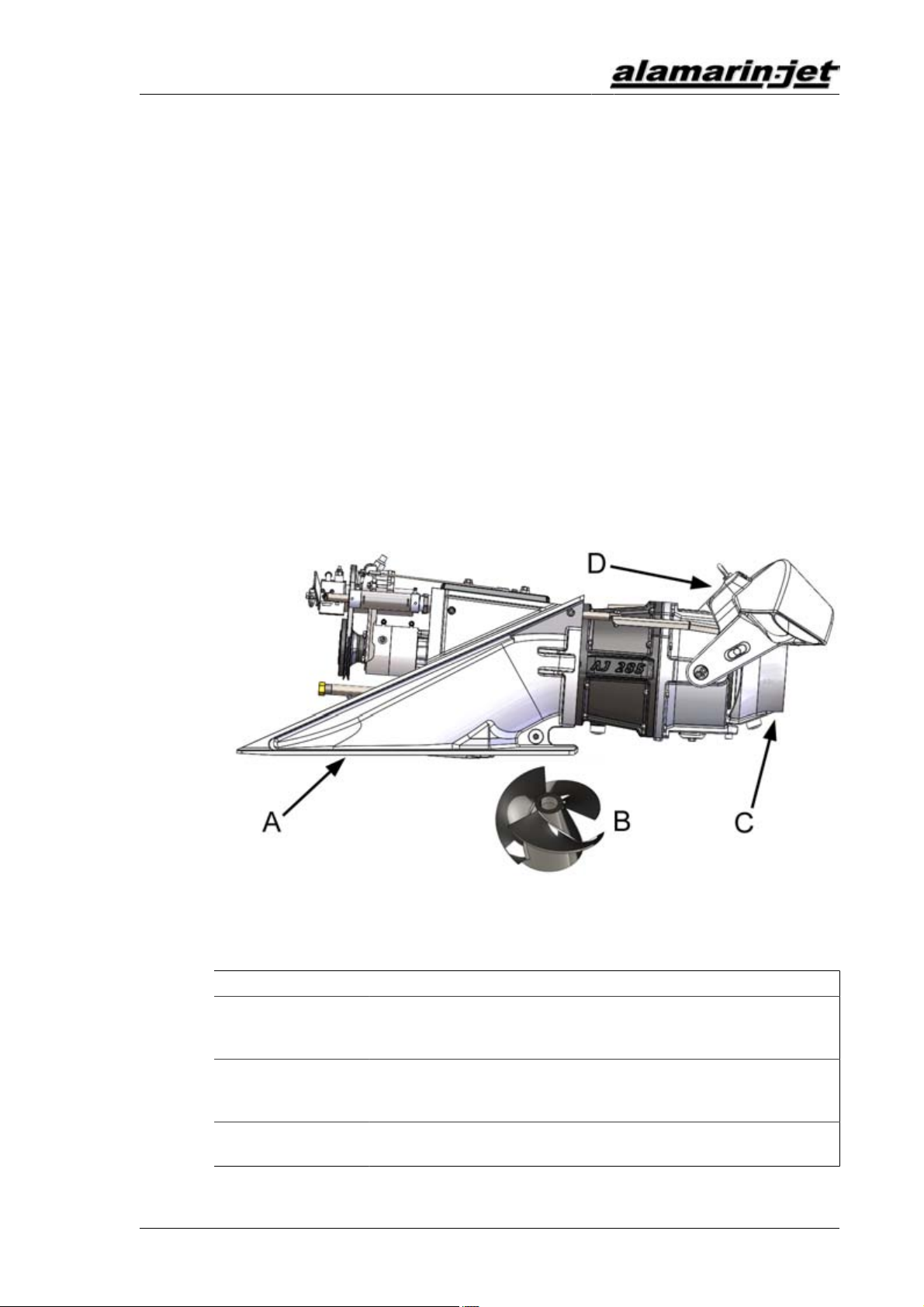
2.1.Structure
The jet consists of four main parts (figure 1). These are specified in the table 2.
Figure1.Main parts of the jet
Table 2. Purpose of the main parts of the jet
Part Purpose
Intake duct (A) Leads the water from outside the boat to the intake side of
the impeller. Keeps the loss of power as small as possible
and distributes velocity evenly.
Impeller (B) Increases the water's flow rate. The impeller is rotated
by the driving motor. The nozzle converts the pressure
energy produced by the impeller into motion energy.
Steering device
(C)
Changes the direction of the jet flow coming out of the
nozzle, which creates the force needed for turning.
The Jet Propulsion Unit
Operation and maintenance manual
4 KHO/285/EN/1.0.0.
Part Purpose
Controlling device
(D)
Causes the boat to reverse and stop. Lowering the
reversing deflector causes the boat to reverse. The
direction of the jet flow changes obliquely forward under
the boat, which is when the thrust is directed forward and
down.
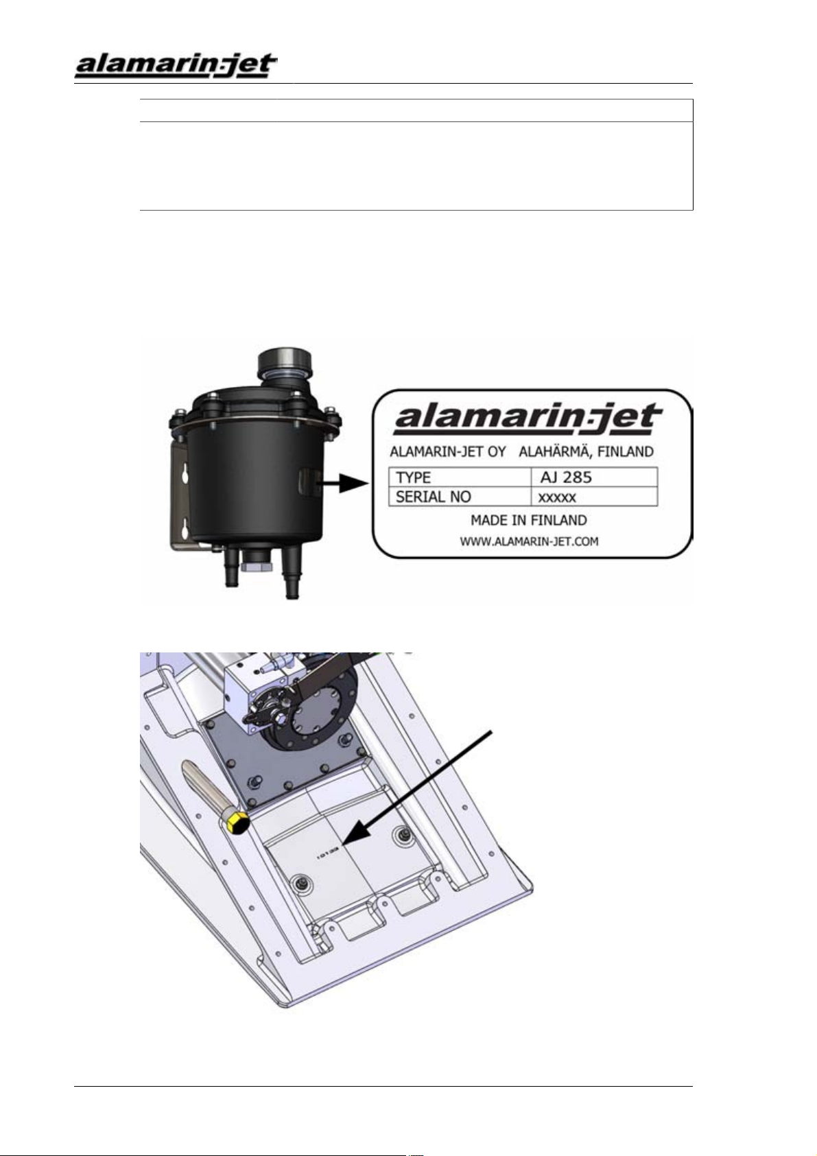
2.2.Serial number
Every jet has a unique serial number. The serial number has been marked on
the type label, which is on the side of the bearing oil reservoir (figure 2). The
serial number is also stamped on the body of the jet under the cooling system
(figure 3).
Figure2.Serial number on the oil reservoir
Figure3.Serial number on the body

Operation
Operation and maintenance manual
KHO/285/EN/1.0.0. 5
3. Operation
If you have never driven a jet boat before, familiarise yourself with the
separate guide “Steering and controlling jet boats” before driving the boat for
the first time.
3.1.Starting
Before you start the engine equipped with the jet, make sure that
• the reversing deflector control lever is in centre position
• the gear is disengaged. (If the engine has no gearbox, it must be in the idle
position before you start it.)
• Note the direction of the jet’s rotation, which usually corresponds to the
direction of the engine’s rotation (counterclockwise from the rear of the
boat). This is why the gear must usually be used in the "reverse" position.
The positions of the reversing deflector control lever are described in section
3.3. Controlling, page 7.
Operation for the first time
CAUTION!
Before you set the boat afloat for the first time, make sure
that the jet has been installed according to the installation
instructions. If you have not personally installed the jet, check
with the boat's retailer that the jet has been installed correctly.
Correct installation helps to prevent the emergence of
unexpected fault situations which can lead to damages.
The jet does not require separate running in. However, follow the engine
manufacturer's instructions about running in during the first few drives.
Ensure the functioning of the jet carefully when driving at low speeds.
DANGER!
The jet can be dangerous when running.
Do not go near the rotating parts.
Do not open the jet's inspection hatch when the engine is
running.
When running, the jet propulsion unit sprays water backwards
at great pressure. Make sure that there is no one in the water
behind the boat!
The intake in the bottom of the boat causes suction power at
the back of the boat when the jet propulsion unit is running.
Make sure that there is no one in the water at risk of being
affected by the intake.
When you start the engine for the first time, you may hear a jingling sound for
a few minutes. This is normal and the sound will disappear when the impeller

Operation
Operation and maintenance manual
6 KHO/285/EN/1.0.0.
gap sets in place. The noise from the oil pump may be loud at first but it will
disappear as the system fills up with oil.
During the first few drives, the reversing deflector's hydraulic control system
needs more oil than usual because the hoses and the cooler are empty. Check
the oil level and add more oil if necessary in accordance with the instructions
in section 4.3.1. Lubricating the front bearing, page 15.
NOTE!
An oil leak may pollute the environment.
Monitor the oil level and make sure that oil does not leak out.
3.2.Steering
WARRANTY!
In this section, controlling the jet boat is described in a way
that it is performed using a system that has been installed as
intended by the manufacturer.
Alamarin-Jet Oy is not liable for damages which derive from
incorrect installation of the system.
Steering denotes exclusively moving the steering nozzle. Steering means
changing the boat's bow angle.
The boat is steered by turning the steering wheel. The steering wheel is
hydraulically connected to the cylinder, which moves the steering nozzle.
Figure4.Steering device
Steering is possible only when the power of the jet flow is sufficient. This is
why the engine must run on sufficiently high revs when steering. A suitable
number of revolutions depends on the engine. Usually it is between 1,000 and
1,500 rpm.
In sharp curves, turning the nozzle causes the boat to slow down. This is
normal and increases safety.
Operation
Operation and maintenance manual
KHO/285/EN/1.0.0. 7
Turning the nozzle from one extreme position to the other takes between
1 and 3 revolutions of the steering wheel, depending on the capacity of the
steering pump used.
TIP!
When the boat is not in use, it is advisable to turn the wheel
all the way to the left. This will protect the cylinder rod and
prevent it from collecting dirt, thus increasing the service life
of the seals.
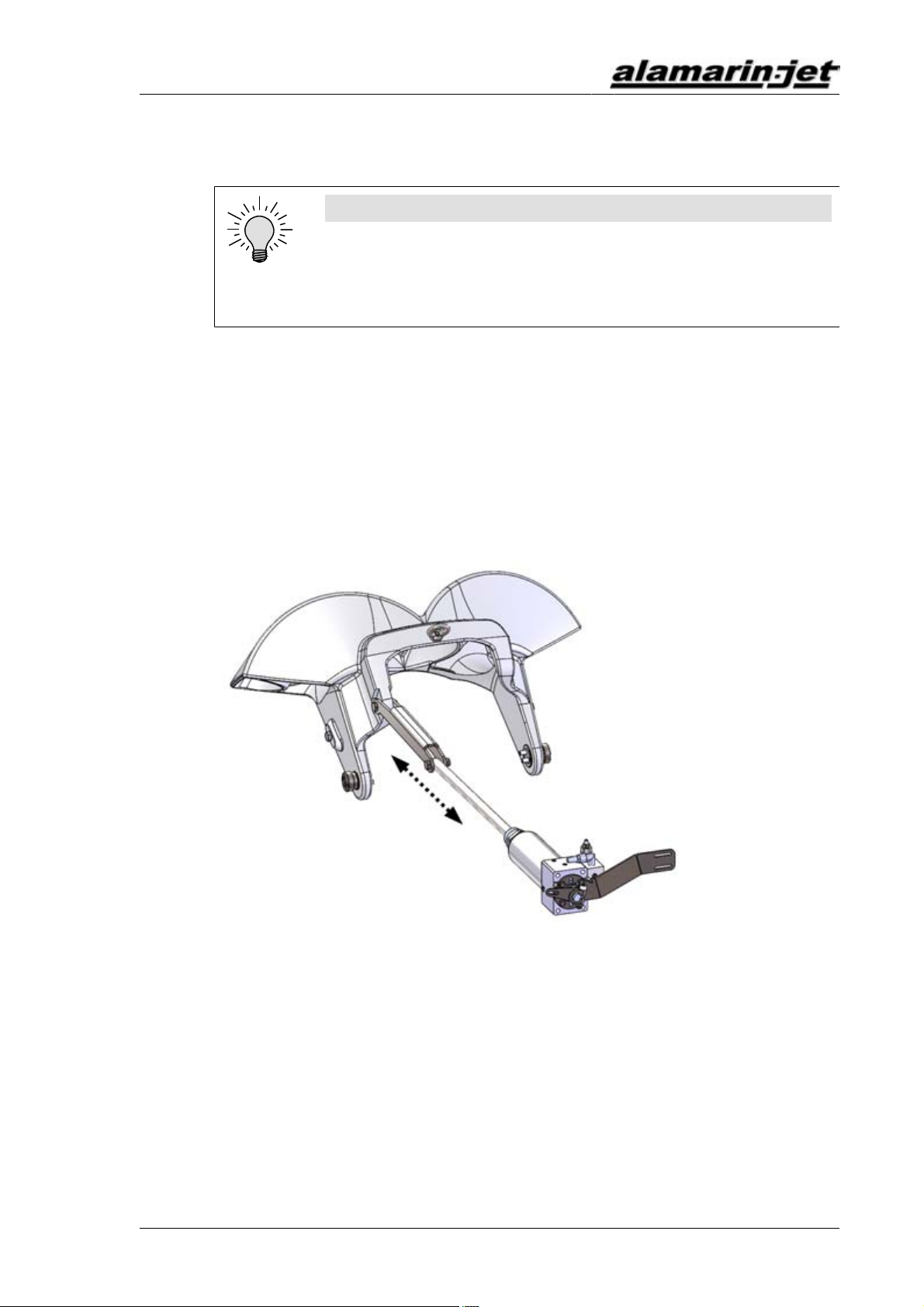
3.3.Controlling
Controlling denotes exclusively moving the reversing deflector. Controlling
means changing the boat's driving direction (forward–astern). The reversing
deflector is moved with the lever, which is usually next to the throttle lever.
The lever controls the hydraulic system mechanically (the cable operates the
cylinder valve)
The reversing deflector can be lowered in front of the jet flow using
hydraulics, causing the boat to reverse (figure 5).
Figure5.Lowering the reversing deflector
3.3.1.The positions of the reversing deflector control lever
The reversing deflector control lever can be in one of three positions: forward,
rear or centre.
Forward position
When the reversing deflector control lever is in the forward position, the
deflector is not blocking the jet flow and the boat moves forward (figure 6).

Operation
Operation and maintenance manual
8 KHO/285/EN/1.0.0.
Figure6.Ahead
A Throttle lever
B Control lever
Rear position
When the reversing deflector control lever is in the rear position, the deflector
is blocking the jet flow and the boat moves astern (figure 7).
Figure7.Astern
A Throttle lever
B Control lever
Centre position
The centre position of the control lever corresponds to the ”idle” position of
the gearbox: even though the drive is on, the boat does not move. The centre
position is not absolute as it depends on the power of the jet flow. You can find
the centre position by testing during the first few driving hours.
Operation
Operation and maintenance manual
KHO/285/EN/1.0.0. 9
TIP!
When the boat is not in use, it is advisable to raise the
reversing deflector into the upright position. This will protect
the cylinder rod and prevent it from collecting dirt, thus
increasing the service life of the seals. For long-term storage,
you can ensure that the reversing deflector stays in the
upright position by tying it from the lifting loop to the stern of
the boat.
3.3.2.Using the reversing deflector
When moving at low speeds, the reversing deflector is used to control the
boat's speed. Because the engine is being run at 1,000–1,500 rpm to enhance
steering, the boat may travel faster than desired. If this is the case, the
deflector can be lowered in front of the jet flow to reduce the thrust directed
towards the driving direction. This does not affect the steerability, which
remains good.
At high speeds, the deflector is not used to reduce speed. Instead, speed is
controlled with engine revolutions.
It is possible to turn the boat in place when the deflector is in the centre
position. When the nozzle is turned in the desired direction, the boat rotates
about its central axis.
When reversing, steering is inversed in comparison to driving forward. If
you want to reverse the boat to the left, you must turn the steering wheel to
the right. A good rule to remember is that the boat's bow always turns in the
same direction as the wheel when reversing. When fast turns are needed, the
engine revolutions are not reduced. Instead, the turn is performed through the
combined motion of the nozzle and the deflector.
Emergency stop
When the boat is running forwards at great speed, it is possible to stop the
boat by only using the reversing deflector. When the reversing deflector is
lowered quickly, the boat stops in a very short distance. The emergency stop is
to be used in emergencies only.
WARNING!
Alert the passengers and tell them to hold on to something if
you are planning an emergency stop. Without being prepared,
a passenger may be thrown overboard.
3.4.Driving under difficult conditions
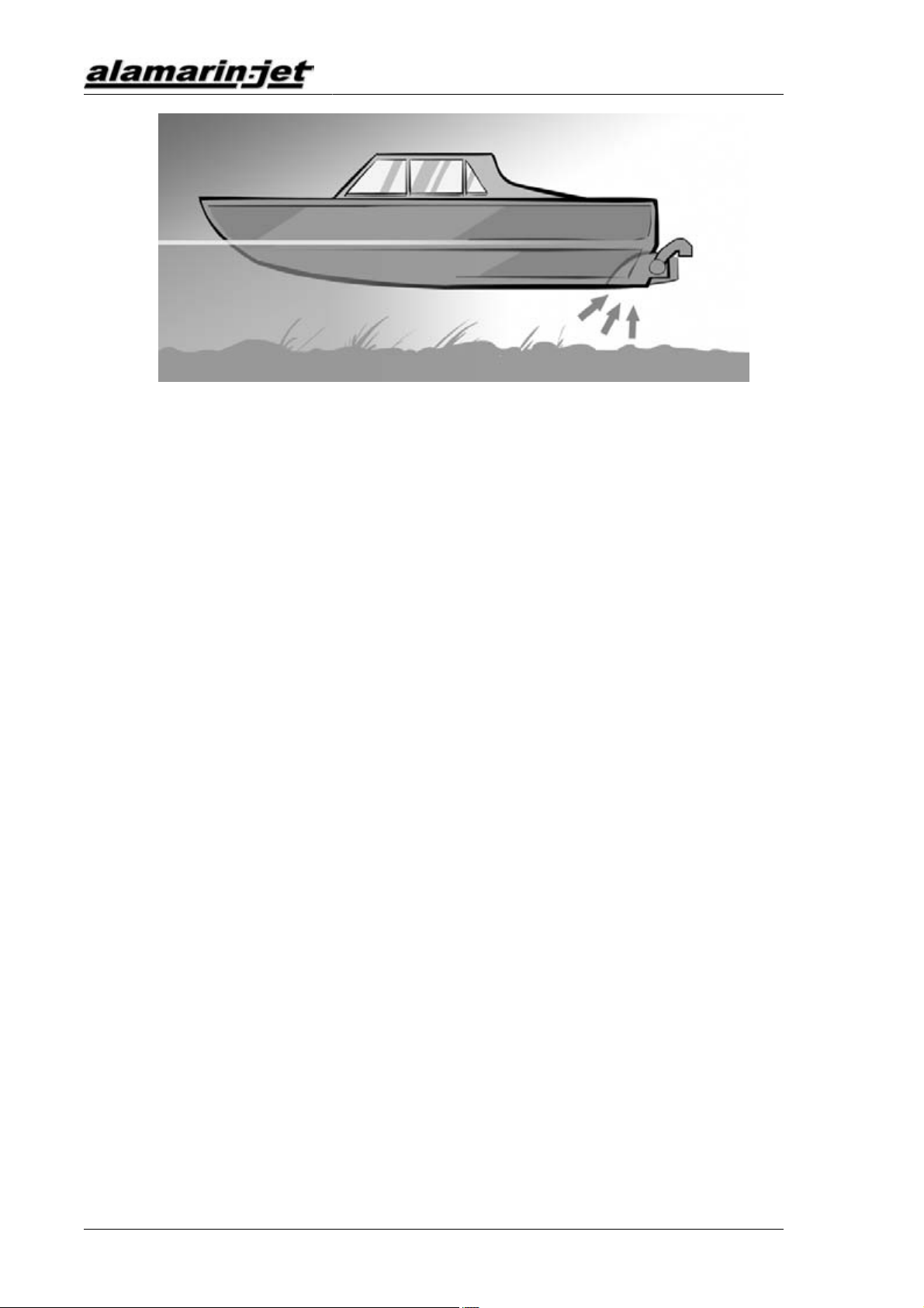
Shallow water
The jet boat can be used in very shallow water. However, note that especially
on high revolutions, the suction power of the intake is high (figure 8).
Operation
Operation and maintenance manual
10 KHO/285/EN/1.0.0.
Figure8.Suction power of the intake
Loose objects may get sucked into the grass rake and small objects may
wash through the jet. Stones may cause damage to the jet and its parts. In
sandy conditions, the impeller inevitably wears. A worn impeller requires
maintenance (section 4.8. Impeller, page 24).
Reed fields
At planing speeds, a jet boat usually crosses reed fields without difficulty. In
difficult conditions, however, clogging may be possible.
A clogged jet must be cleaned immediately (section 5.3. Clogged jet, page
35).
3.5.Dry running
The jet may be run by the engine even out of the water, because the bearings
are greased and oiled. This is a significant benefit in comparison to water-
lubricated bearings, which do not sustain dry running well.
During dry runs, a temporary water inlet must be arranged for the motor sea
water cycle to cool the engine.
Maintenance
Operation and maintenance manual
KHO/285/EN/1.0.0. 11
4. Maintenance
The jet is designed and manufactured to be as simple as possible. This is why
the need for maintenance is low and maintenance can be carried out on shore.
However, maintenance must be performed regularly and whenever the need
arises.
Alamarin-Jet can provide you with a toolkit, available through separate order,
for maintenance purposes. The toolkit includes the tools needed to perform
most maintenance and repair procedures on the jet. The tools included in the
toolkit are specified in table 3.
Table 3. Toolkit
Tool Pcs Size
Wrench 5 10, 13, 17 mm
Allen wrench 4 5, 6, 8, 10 mm
Knife 1 -
Universal pliers 1 -
Feeler gauge 1 -
4.1.Washing
Washing the jet regularly removes possible salt accruals and impurities, thus
reducing the risk of corrosion.
Every time you lift the jet out of the water, it is a good idea to rinse it with
fresh water.
4.2.Corrosion protection
The jet has been protected against corrosion in the manufacturing and
installation phases. However, the protection requires regular maintenance.
4.2.1.Changing the anodes
The main raw materials used for manufacturing the jet parts are aluminium,
acid-proof steel and plastic. Materials that have different electrochemical
properties can form a galvanic couple when they are submerged in electrolytic
fluid (salt water). A galvanic couple forms an electrical circuit because the
materials have different inherent voltages. This in turn leads to electron
movement and corrosion of the weaker material.
Cathodic protection is used to prevent the propagation of galvanic corrosion.
Cathodic protection means introducing a third material with weaker
electrochemical properties into the same circuit.

Maintenance
Operation and maintenance manual
12 KHO/285/EN/1.0.0.
The jet is protected from galvanic corrosion with passive cathodic protection,
i.e. with anodes. Every critical aluminium casting has its own anode. The
locations of the anodes are shown in figure 9.
Figure9.Anodes
A Steering nozzle (1 pc)
B Stator (1 pc)
C Reversing deflector (2 pcs)
D Impeller tunnel (1 pc)
E Stator, inside (1 pc)
F Body (2 pcs)
G Inspection hatch (1 pc)
The functioning of the anodes is absolutely crucial to prevent corrosion. The
anodes must be replaced when they have worn down to half their original size.
Replacing the anodes:
Most of the anodes are attached with simple screws. Below you will find
instructions for changing the anodes that are attached differently.
Replacing the stator anode
Maintenance
Operation and maintenance manual
KHO/285/EN/1.0.0. 13
Figure10.Stator anode
The stator is protected by an anode housed under a plastic plug located on the
starboard side the stator. To remove the anode, first open the arrester screw
(figure 10, point A) and unscrew the plug. Now you can replace the anode
located inside the plug. Leave the screw that holds the anode in place (figure
10, point B) loose and fasten the plug into place using a sealing compound
(such as Sikaflex 221). Only then attach the other end of the arrester to the
stator. After this, tighten the screw that holds the anode in place.
4.2.2.Touch-up painting and antifouling
The aluminium castings have been protected with paint. Painting efficiently
prevents the propagation of various forms of corrosion, e.g. pit corrosion.
Bare aluminium, on the other hand, is liable to corrosion in difficult conditions.
This is why it is important to carry out touch-up painting if paint comes loose
and aluminium is exposed. Touch-up painting can be done in various ways.
What is important is that the paints used are suitable for aluminium and that
the paint manufacturer's instructions are followed during painting.
If the boat is going to be used in waterways where the growth and sticking
of organisms around the boat’s bottom and the propulsion unit is heavy,
the propulsion unit can be painted with antifouling paint after installation.
Generally speaking, antifouling paints are based on various soluble
substances, such as copper. Because the propulsion unit is made mainly of
aluminium, copper forms a highly unfavourable galvanic couple with the
propulsion unit. In other words, the aluminium starts to corrode because it
functions as an anode.

Maintenance
Operation and maintenance manual
14 KHO/285/EN/1.0.0.
WARNING!
Familiarise yourself with antifouling before painting the
propulsion unit with antifouling paint! Painting the propulsion
unit with antifouling paint that contains copper will result in
heavy corrosion and destruction of the propulsion unit. Do not
use any other antifouling paints for painting the propulsion
unit except those intended for aluminium surfaces.
A boat bottom made of reinforced plastic can be painted using antifouling
paint that contains copper. In this case, leave a 50 mm (2") unpainted area
around the propulsion unit in the stern and on the bottom of the boat (figure
11).
Figure11.Antifouling
A Unpainted area
B Painted area
CAUTION!
Do not paint the anodes or their fastening screws.
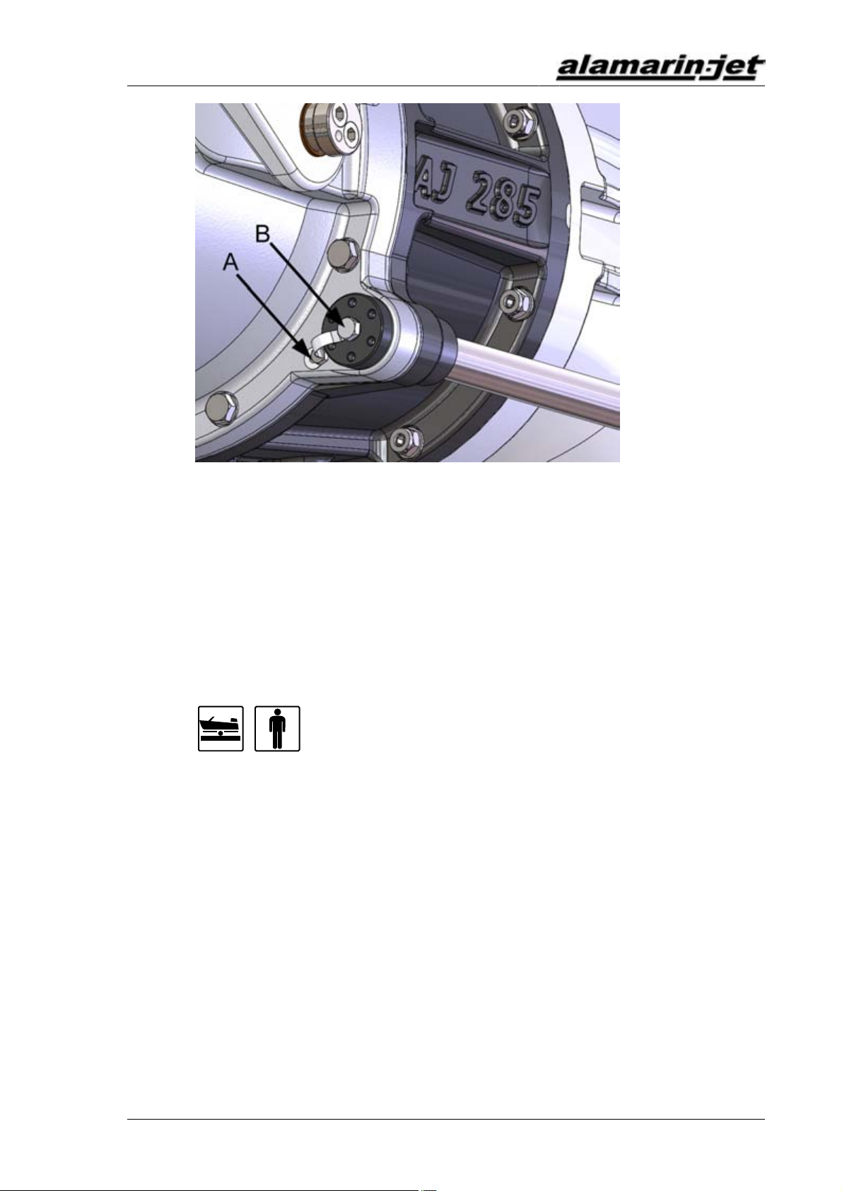
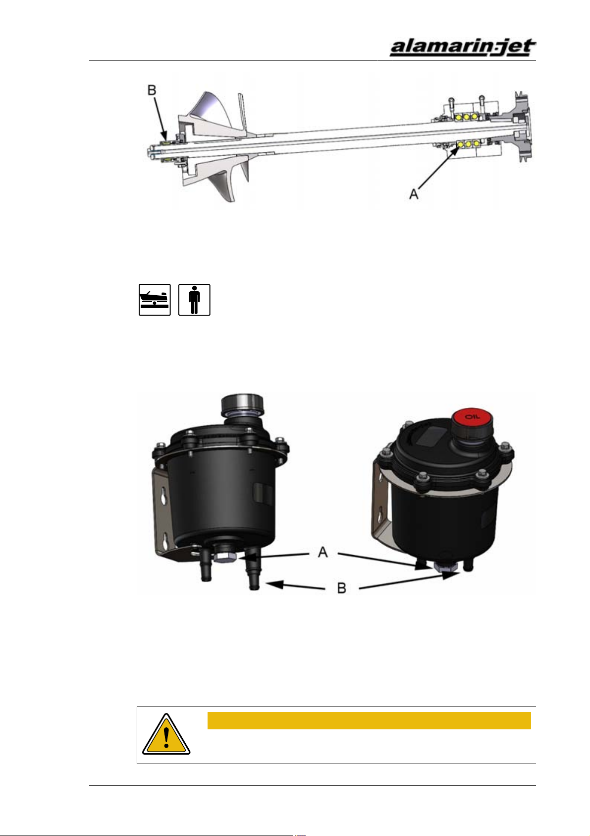
4.3.Bearing
The jet's bearing is very simple. There are bearings at both ends of the direct
shaft. The structure of the front bearing (figure 12, point A) is receptive to
axial pressure. It also carries the radial loads caused by the weight of the
shaft and the parts attached to it. At the rear end, a grease lubricated needle
bearing supports the shaft (figure 12, point B). A water-lubricated bushing can
also be used.
Maintenance
Operation and maintenance manual
KHO/285/EN/1.0.0. 15
Figure12.Bearing
4.3.1.Lubricating the front bearing
The front bearing is oil-lubricated and the housing is secured with a
mechanical sealing. When the shaft rotates, the oil circulates through the
reservoir and impurities gather to the bottom of the reservoir on the drain
plug magnet (figure 13, point A).
Figure13.Drain plug magnet and oil return hose
A Drain plug magnet
B Oil reservoir return hose connection
Oil change
WARNING!
Use protective gloves while handling oil.

Maintenance
Operation and maintenance manual
16 KHO/285/EN/1.0.0.
The front bearing oil must be changed after the first 20 hours of driving and
then after every 500 hours or once every driving season.
Before you start changing the oil, make sure you have a container for draining
the used oil.
Changing the oil:
1. Open the reservoir cap and stir the oil inside.
Impurities are easier to remove from the reservoir when they are mixed in
with the oil.
2. Open the drain plug (figure 13, point A) and drain the oil into the
container.
3. Clean the plug magnet, close the drain plug and fill the reservoir
with new oil. Oil recommendations can be found in appendix 3. Oil
recommendations, page 41.
This prevents air from drifting into the system and ensures that lubrication
functions well from the start.
4. Remove the reservoir return hose (figure 13, point B) and keep it below
the reservoir.
This way the oil drains out from the bearing housing and the hoses and
the system fills up with new oil. The time it takes to drain the oil depends
on how far the reservoir is from the bearing housing. The colour of the oil
indicates whether all the old oil has drained out. The system can have a
maximum volume of up to 1 L, depending on the length of the hoses.
5. Attach the oil return hose to the reservoir once the system is filled with
new oil.
6. Check the oil level from the dipstick on the reservoir cap (figure 21, point
B).
When the shaft starts to rotate, the system generates pressure into the
return line, causing oil to start circulating in the system.
4.3.2.Lubrication of the rear end bearing
The rear end bearing is lubricated from the engine room with petroleum jelly.
The lubrication channel runs from the engine room to the rear end bearing
housing.
An automatic lubrication unit that makes sure that the rear end bearing is
lubricated regularly is available as an accessory.
Other manuals for AJ 285
2
Table of contents


