BRP EVINRUDE E-TEC 200 User manual


Printed in the United States.
© 2011 BRP US Inc. All rights reserved.
TM, ® Trademarks and registered trademarks of Bombardier Recreational Products Inc. or its affiliates.
BRP US Inc.
Technical Publications
P.O. Box 597
Sturtevant, Wisconsin 53177 United States
www.evinrude.com or www.johnson.com
† AMP, Superseal 1.5, Super Seal, Power Timer, and Pro-Crimper II
are registered trademarks of Tyco International, Ltd.
† Amphenol is a registered trademark of The Amphenol Corporation.
† BEP is a registered trademark of Actuant Corporation.
† Champion is a registered trademark of Federal-Mogul Corporation.
† Deutsch is a registered trademark of The Deutsch Company.
† Dexron is a registered trademark of The General Motors Corporation.
† Fluke is a registered trademark of The Fluke Corporation
† GE is a registered trademark of The General Electric Company.
† GM is a registered trademark of The General Motors Corporation.
† Locquic and Loctite are registered trademarks of The Henkel Group.
† Lubriplate is a registered trademark of Fiske Brothers Refining Company.
† NMEA is a registered trademark of the National Marine Electronics Association.
† Oetiker is a registered trademark of Hans Oetiker AG Maschinen.
† Packard is a registered trademark of Delphi Automotive Systems.
† Permatex is a registered trademark of Permatex.
† STP is a registered trademark of STP Products Company.
† Snap-on is a registered trademark of Snap-on Technologies, Inc.
The following trademarks are the property of BRP US Inc. or its affiliates:
Evinrude ® Twist Grip™
Johnson ® Nut Lock™
Evinrude ® E-TEC ® Screw Lock™
FasTrak™ Ultra Lock™
S.A.F.E.™ Moly Lube™
SystemCheck™ Triple-Guard ® Grease
I-Command™ DPL™ Lubricant
Evinrude ® ICON™ 2+4 ® Fuel Conditioner
Evinrude ® / Johnson ® XD30™ Outboard Oil Carbon Guard™
Evinrude ® / Johnson ® XD50™ Outboard Oil HPF XR™ Gearcase Lubricant
Evinrude ® / Johnson ® XD100™ Outboard Oil HPF PRO™ Gearcase Lubricant
Gel-Seal II™

2
SERVICE MANUAL
CONTENTS
SECTION . . . . . . . . . . . . . . . . . . . . . . . . . . . . . . . . . . . . PAGE
1 REFERENCE INFORMATION . . . . . . . . . . . . . . . . . . . . . 3
2 ROUTINE SERVICE . . . . . . . . . . . . . . . . . . . . . . . . . . . . 15
3 ENGINE COVER SERVICE . . . . . . . . . . . . . . . . . . . . . . 49
4 ENGINE MANAGEMENT MODULE (EMM) . . . . . . . . . . 53
5 SYSTEM ANALYSIS . . . . . . . . . . . . . . . . . . . . . . . . . . . . 73
6 ELECTRICAL AND IGNITION . . . . . . . . . . . . . . . . . . . . . 87
7 FUEL SYSTEM . . . . . . . . . . . . . . . . . . . . . . . . . . . . . . . 127
8 OILING SYSTEM . . . . . . . . . . . . . . . . . . . . . . . . . . . . . 155
9 COOLING SYSTEM . . . . . . . . . . . . . . . . . . . . . . . . . . . 183
10 EVINRUDE ICON REMOTE CONTROL SYSTEM . . . . 195
11 POWERHEAD . . . . . . . . . . . . . . . . . . . . . . . . . . . . . . . . 215
12 MIDSECTION . . . . . . . . . . . . . . . . . . . . . . . . . . . . . . . . 259
13 GEARCASE . . . . . . . . . . . . . . . . . . . . . . . . . . . . . . . . . 281
GEARCASE – STANDARD ROTATION . . . . . . . . . . . . 296
GEARCASE – COUNTER ROTATION . . . . . . . . . . . . . 319
14 TRIM AND TILT . . . . . . . . . . . . . . . . . . . . . . . . . . . . . . . 331
SAFETY . . . . . . . . . . . . . . . . . . . . . . . . . . . . . . . . . . . . . . . S-1
INDEX . . . . . . . . . . . . . . . . . . . . . . . . . . . . . . . . . . . . . . . . . . I-1
TROUBLE CHECK CHART . . . . . . . . . . . . . . . . . . . . . . . . T-1
DIAGRAMS
IMPORTANT: For complete outboard rigging and control installation information, refer to the Predeliv-
ery and Installation Guide included with the service manual set.
All special tools referenced in this manual can be found in the Special Tools Guide, P/N 5008526.

REFERENCE INFORMATION
3
1
REFERENCE INFORMATION
TABLE OF CONTENTS
SAFETY NOTICE . . . . . . . . . . . . . . . . . . . . . . . . . . . . . . . . . . . . . . . . . . . . . . . . . . . . . . . . . . . . . . . . . . . . . 4
ABBREVIATIONS USED IN THIS MANUAL . . . . . . . . . . . . . . . . . . . . . . . . . . . . . . . . . . . . . . . . . . . . . . . .6
UNITS OF MEASUREMENT . . . . . . . . . . . . . . . . . . . . . . . . . . . . . . . . . . . . . . . . . . . . . . . . . . . . . . . . . . . . 6
LIST OF ABBREVIATIONS . . . . . . . . . . . . . . . . . . . . . . . . . . . . . . . . . . . . . . . . . . . . . . . . . . . . . . . . . . . . . 6
EMISSION-RELATED INSTALLATION INSTRUCTIONS . . . . . . . . . . . . . . . . . . . . . . . . . . . . . . . . . . . . . . 7
MANUFACTURER’S RESPONSIBILITY . . . . . . . . . . . . . . . . . . . . . . . . . . . . . . . . . . . . . . . . . . . . . . . . . . . . 7
DEALER’S RESPONSIBILITY . . . . . . . . . . . . . . . . . . . . . . . . . . . . . . . . . . . . . . . . . . . . . . . . . . . . . . . . . . . 7
OWNER’S RESPONSIBILITY . . . . . . . . . . . . . . . . . . . . . . . . . . . . . . . . . . . . . . . . . . . . . . . . . . . . . . . . . . . 7
EPA EMISSION REGULATIONS . . . . . . . . . . . . . . . . . . . . . . . . . . . . . . . . . . . . . . . . . . . . . . . . . . . . . . . . . 7
MODEL DESIGNATION . . . . . . . . . . . . . . . . . . . . . . . . . . . . . . . . . . . . . . . . . . . . . . . . . . . . . . . . . . . . . . . . 8
MODELS COVERED IN THIS MANUAL . . . . . . . . . . . . . . . . . . . . . . . . . . . . . . . . . . . . . . . . . . . . . . . . . . . 9
SERVICE SPECIFICATIONS . . . . . . . . . . . . . . . . . . . . . . . . . . . . . . . . . . . . . . . . . . . . . . . . . . . . . . . . . . . 10
STANDARD TORQUE SPECIFICATIONS . . . . . . . . . . . . . . . . . . . . . . . . . . . . . . . . . . . . . . . . . . . . . . . .14
PRODUCT REFERENCE AND ILLUSTRATIONS . . . . . . . . . . . . . . . . . . . . . . . . . . . . . . . . . . . . . . . . . . . 14

SAFETY NOTICE
Before working on any part of the outboard, read the SAFETY section at the end of this manual.
This pu blication is written fo r qualified, facto ry-
trained technicia ns who ar e alrea dy familiar with
the use of Evinrude/Johnson Special Tools. The
included in formation is not a substitu te for wo rk
experience. It is an organized guide for reference,
repair, and/or maintenance.
The following sym bols and /or signal words
may be used in this document:
Indicates a n in struction which, if
not followed, could severely damage engine
components or other property.
These safety alert signal words mean:
ATTENTION!
BECOME ALERT!
YOUR SAFETY IS INVOLVED!
IMPORTANT: Identifies information that controls
correct assembly and operation of the product.
DO NOT perform any work unt il yo u have read
and understood these instructions completely.
Torque wre nch tig htening specifications must
strictly be adhered to.
Should removal of any locking fastener (lock tabs,
locknuts, or p atch screws) be requ ired, a lways
replace with a new one.
When repla cement p arts are required, use
Evinrude/Johnson Genuine Parts or parts with
equivalent characteristics, including type, strength
and mate rial. Use of subst andard p arts could
result in injury or product malfunction.
Always wear EYE PROTECTION AND APPRO-
PRIATE GLOVES when using power tools.
Unless otherwise specified, engine must be OFF
when performing this work.
Always be aware of p arts that can move, such as
flywheels, propellers, etc.
Some components may be HOT. Always wait for
engine to cool down before performing work.
If you use procedures or service tools that are not
recommended in th is manual, YOU ALONE must
decide if your actions might injure people or dam-
age the outboard.
This document ma y be tra nslated into othe r la n-
guages. In the event o f an y discrepancy, t he
English version shall prevail.
A DANGER
Indicates a h azardous situation which, i f
not avoided, will re sult in death or serious
injury.
A WARNING
Indicates a h azardous situation which, i f
not avo ided, could result in death or seri-
ous injury
A CAUTION
Indicates a h azardous situation which, i f
not avoided, could result in minor or mod -
erate personal injury.
NOTICE

1
A DANGER
Contact with a rot ating prope ller is likely to result in seriou s injury or death. Assure the
engine and prop area is clear of people and objects before starting engine or operating boat.
Do not allow anyon e near a pro peller, even when the engine is off. Blades can be sharp and
the propeller can continue to turn even after the engine is off. Remove propeller before ser-
vicing and when running the outboard on a flushing device.
DO NOT run the e ngine indoors or with out adequate ventilation or permi t exhaust fumes to
accumulate in confine d areas. Engin e exhaust contains carbon mo noxide which, i f inhaled,
can cause serious brain damage or death.
A WARNING
Wear safety glasses to avoid personal injury, and set compressed air to less than 25 psi (172
kPa).
The mo tor cov er an d fly wheel c over are m achinery guards. Use caution when con ducting
tests on running outb oards. DO NOT wear jewelry or loose clo thing. Keep hai r, hands, and
clothing away from rotating parts.
During service, the outboard may drop unexpe ctedly. Avoid personal injury; always suppo rt
the outboard’s weight with a suitable hoist or the tilt support bracket during service.
To prevent acc idental starting while servicing, disconnect the battery cables at the battery.
Twist and remove all spark plug leads.
The electrical system presents a serious shock hazard. DO NOT handle primary or secondary
ignition components while outboard is running or flywheel is turning.
Gasoline is extremely flammable and highly explosive under certain conditions. Use caution
when working on any part of the fuel system.
Protect a gainst h azardous fuel sp ray. Befo re st arting a ny fuel s ystem service, carefully
relieve fuel system pressure.
Do not smo ke, or allow open flame s or sparks, or use ele ctrical devi ces such as cellula r
phones in the vicinity of a fuel leak or while fueling.
Keep all electrical connections clean, tight, and insu lated to preve nt shorting or arcing and
causing an explosion.
Always work in a well ventilated area.
Replace any lo cking fastener (locknut or p atch screw) if it s locking feature bec omes weak.
Definite resistance to tightening must be felt when reusing a locking fastener. If replacement
is indicated, use only authorized replacement or equivalent.

6
REFERENCE INFORMATION
ABBREVIATIONS USED IN THIS MANUAL
Units of Measurement List of Abbreviations
A Amperes
amp-hr Ampere hour
fl. oz. fluid ounce
ft. lbs. foot pounds
HP horsepower
in. inch
in. Hg inches of mercury
in. lbs. inch pounds
kPa kilopascals
ml milliliter
mm millimeter
N·m Newton meter
P/N part number
psi pounds per square inch
RPM revolutions per minute
°C degrees Celsius
°F degrees Fahrenheit
ms milliseconds
µs microseconds
ΩOhms
VVolts
VAC Volts Alternating Current
VDC Volts Direct Current
ABYC American Boat & Yacht Council
ATDC after top dead center
AT air temperature sensor
BPS barometric pressure sensor
BTDC before top dead center
CCA cold cranking amps
CFR Code of Federal Regulations
CPS crankshaft position sensor
EMM Engine Management Module
EPA Environmental Protection Agency
ICOMIA International Council of Marine
Industry Associations
ID Inside dimension
MCA marine cranking amps
MWS modular wiring system
NMEA National Marine Electronics Assoc.
ROM read only memory
S.A.F.E. speed adjusting failsafe electronics
SAC start assist circuit
SAE Society of Automotive Engineers
SYNC synchronization
TDC top dead center
TPS throttle position sensor
USCG United States Coast Guard
WOT wide open throttle
WTS water temperature sensor

7
REFERENCE INFORMATION
EMISSION-RELATED INSTALLATION INSTRUCTIONS
1
EMISSION-RELATED
INSTALLATION
INSTRUCTIONS
Failing to follow these instructio ns when
installing a certified engine in a vessel violates
federal l aw (40 CFR 1 068.105 (b )), s ubject to
fines or other penaltie s as described in the
Clean Air Act.
Maintenance, replacement, or rep air of the emis-
sion control de vices and systems ma y be per-
formed by any ma rine SI (sp ark ig nition) engine
repair establishment or individual.
Manufacturer’s Responsibility
Beginning with 1 999 model year o utboards, man-
ufacturers o f ma rine outboards must de termine
the exha ust emissio n levels for each outbo ard
horsepower family and certif y the se o utboards
with the Unite d States of America Environmental
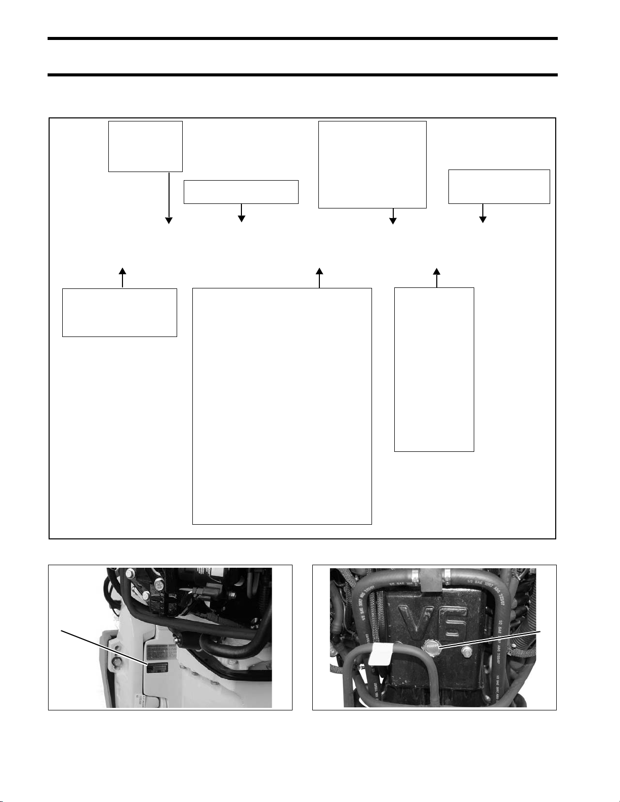
Protection Age ncy (EP A). An emissions control
information labe l, showing emission leve ls a nd
outboard specifications, mu st be placed o n each
outboard at the time of manufacture.
Dealer’s Responsibility
When pe rforming service on all 1 999 a nd more
recent Evinrude/Johnson outboards that carry an
emissions control information la bel, adjustments
must be kept with in pub lished factory specifica-
tions.
Replacement or repair of any emission rela ted
component must b e exe cuted in a manne r that
maintains emission levels within the prescrib ed
certification standards.
Dealers are not to mo dify the outbo ard in an y
manner that would alter the horsepower or allow
emission levels to excee d their predete rmined
factory specifications.
Exceptions include manu facturer’s prescrib ed
changes, such as altitude ad justments, for exa m-
ple.
Owner’s Responsibility
The owner/operator is required to have outboa rd
maintenance performed to maintain emission lev-
els within prescribed certification standards.
The owner/operator is not to, and should not allow
anyone to, modify the outboard in any manner
that wo uld a lter th e horsepower or a llow e mis-
sions levels to exceed their predetermined factory
specifications.
Tampering with the fuel system to change horse-
power or mo dify emission levels beyond fa ctory
settings or specifications will void the product war-
ranty.
EPA Emission Regulations
All new 19 99 and more recent Evinrude/Johnson
outboards are certified to the EPA as confo rming
to the requirements of the regulations for the con-
trol of air pollutio n from new watercraf t marine
spark ignition outboards. This certification is con-
tingent on certain adjustments being set to factory
standards. For this reason, the factory procedure
for servicing the product must be strictly followe d
and, whe never pra ctical, ret urned to the original
intent of the design. The responsibilities liste d
above are gen eral and in no way a comple te list-
ing of the r ules and reg ulations pertaining to th e
EPA re quirements on e xhaust emissions for
marine products. For more detailed information on
this subject, you may cont act th e fo llowing loca-
tions:
VIA U.S. POSTAL SERVICE:
Office of Mobile Sources
Engine Programs and Compliance Division
Engine Compliance Programs Group (6403J)
401 M St. NW
Washington, DC 20460
VIA EXPRESS or COURIER MAIL:
Office of Mobile Sources
Engine Programs and Compliance Division
Engine Compliance Programs Group (6403J)
501 3rd St. NW
Washington, DC 20001
EPA INTERNET WEB SITE:
www.epa.gov

8
REFERENCE INFORMATION
MODEL DESIGNATION
MODEL DESIGNATION
Model and serial numbers are located on the swivel bracket and on the powerhead.
B E 200 DP X IN E
STYLE:
J = Johnson
E = Evinrude
HORSEPOWER
LENGTH:
= 15” Std.
L = 20” Long
Y = 22.5” Special
X = 25” X-long
Z = 30” XX-long
MODEL YR:
I= 1
N= 2
T= 3
R= 4
O= 5
D= 6
U= 7
C= 8
E= 9
S= 0
Ex: IN = 2012
MODEL RUN
or SUFFIX
DESIGN FEATURES:
B = Blue Paint
C = Counter Rotation
D = Evinrude E-TEC®
E = Electric Start w/Remote Steering
F = Direct-Injection
G = Graphite Paint
H = High Output
J = Jet Drive
M = Military
P = Power Trim and Tilt
R = Rope Start w/Tiller Steering
S = Saltwater Approved
T = Tiller Steering
TE = Tiller Electric
V = White Paint
W = Commercial Model
PREFIX:
B = Bodensee model
D = ICON model
1. Model and serial number 000449
1
1. Serial number 006828
1

REFERENCE INFORMATION
MODELS COVERED IN THIS MANUAL
9
1
MODELS COVERED IN THIS MANUAL
This manual covers service information on all 200.1 cubic inch (3.3 L) and 210 cubic inch (3.4 L), 90° V
Evinrude E-TEC models.
Model Displacement Gearcase Height Color Description
E200HSLINE 3.3 L, 200.1 ci .538 L2 20" White Stainless Steering Arm , H.O./Standard Styling
E200HVLINM 3.3 L, 200.1 ci .542 M2 20" White Stainless Steering Arm , H.O./Standard Styling
E200DHLINS 3.3 L, 200.1 ci .538 L2 20" Blue Steel Steering Arm , H.O./Standard Styling
E200DHXINE 3.3 L, 200.1 ci .542 M2 25" White Stainless Steering Arm, H.O./Standard Styling
E200HCXINE 3.3 L, 200.1 ci .542 M2 CR 25" White Stainless Steering Arm , H.O./Standard Styling
E225DPLINS 3.3 L, 200.1 ci .542 M2 20" Blue Steel Steering Arm, Standard Styling
E225DPXINS 3.3 L, 200.1 ci .542 M2 25" White Stainless Steering Arm, Standard Styling
E225DCXINS 3.3 L, 200.1 ci .542 M2 CR 25" White Stainless Steering Arm , Standard Styling
E225DPZINS 3.3 L, 200.1 ci .542 M2 30" White Stainless Steering Arm , Standard Styling
E225DCZINS 3.3 L, 200.1 ci .542 M2 CR 30" White Stainless Steering Arm , Standard Styling
E225HSLINM 3.3 L, 200.1 ci .542 M2 20" White Stainless Steering Arm, H.O. Styling
E225DHLINS 3.3 L, 200.1 ci .542 M2 20" Blue Steel Steering Arm, H.O. Styling
E225DHXIND 3.3 L, 200.1 ci .542 M2 25" Blue Stainless Steering Arm , H.O. Styling
E250DPLINS 3.3 L, 200.1 ci .542 M2 20" Blue Steel Steering Arm, Standard Styling
E250DPXINS 3.3 L, 200.1 ci .542 M2 25" White Stainless Steering Arm, Standard Styling
DE250PXINR 3.3 L, 200.1 ci .542 M2 25" White ICON Control, Stainless Steering Arm , Std Styling
E250DCXINS 3.3 L, 200.1 ci .542 M2 CR 25" White Stainless Steering Arm , Standard Styling
DE250CXINR 3.3 L, 200.1 ci .542 M2 CR 25" White ICON Control, Stainless Steering Arm , Std Styling
E250DPZINS 3.3 L, 200.1 ci .542 M2 30" White Stainless Steering Arm , Standard Styling
DE250PZINR 3.3 L, 200.1 ci .542 M2 30" White ICON Control, Stainless Steering Arm , Std Styling
E250DCZINS 3.3 L, 200.1 ci .542 M2 CR 30" White Stainless Steering Arm, Standard Styling
DE250CZINR 3.3 L, 200.1 ci .542 M2 CR 30" White ICON Control, Stainless Steering Arm , Std Styling
E250HSLINA 3.4 L, 210 ci .542 M2 20" White Stainless Steering Arm , H.O. Styling
E250DHLINM 3.4 L, 210 ci .542 M2 20" Blue Steel Steering Arm, H.O. Styling
E250DHXINM 3.4 L, 210 ci .542 M2 25" Blue Stainless Steering Arm, H.O. Styling
E300DSLINA 3.4 L, 210 ci .542 M2 20" White Stainless Steering Arm , Standard Styling
E300DPXINM 3.4 L, 210 ci .542 M2 25" White Stainless Steering Arm , Standard Styling
DE300PXINR 3.4 L, 210 ci .542 M2 25" White ICON Control, Stainless Steering Arm , Std Styling
E300DPZINM 3.4 L, 210 ci .542 M2 30" White Stainless Steering Arm , Standard Styling
DE300PZINR 3.4 L, 210 ci .542 M2 30" White ICON Control, Stainless Steering Arm , Std Styling
E300DCXINM 3.4 L, 210 ci .542 M2 CR 25" White Stainless Steering Arm , Standard Styling
DE300CXINR 3.4 L, 210 ci .542 M2 CR 25" White ICON Control, Stainless Steering Arm , Std Styling
E300DCZINM 3.4 L, 210 ci .542 M2 CR 30" White Stainless Steering Arm , Standard Styling
DE300CZINR 3.4 L, 210 ci .542 M2 CR 30" White ICON Control, Stainless Steering Arm , Std Styling

10
REFERENCE INFORMATION
SERVICE SPECIFICATIONS
ENGINE
HP 200 225 250
Full Throttle
Operating Range 4500–5800 RPM
Power
200 HP
(147.1 kw)
@ 5150 RPM
225 HP
(165.5 kw)
@ 5150 RPM
250 HP (183.9 kw)
@ 5150 RPM
Idle RPM in Gear 500 ± 50
Test Propeller Standard Rotation Models: P/N 436080 or P/N 396277
Counter Rotation Models: P/N 436081 or P/N 398674
Weight
(may vary depending
on model)
20 in. (L) Models: 503 lbs. (228 kg)
25 in. (X) Models: 524 lbs. (238 kg)
30 in. (Z) Models: 530 lbs. (240 kg)
Lubrication Evinrude/Johnson XD100 Oil
Refer to Recommended Lubricants on p. 164
Engine Type 90° V 6-Cylinder Loop-Charged
Displacement 200.1 cu. in. (3279 cm3)
Bore 3.854 in (97.89 mm)
Stroke 2.858 in. (72.60 mm)
Standard Bore 3.8535 to 3.8545 in. (97.87 to 97.90 mm)
To bore oversize, add piston oversize dimension to standard bore
Top Crankshaft Journal 1.6199 to 1.6204 in. (41.15 to 41.16 mm)
Center Crankshaft Journals 2.1870 to 2.1875 in. (55.55 to 55.56 mm)
Bottom Crankshaft Journal 1.5747 to 1.5752 in. (40.0 to 40.01 mm)
Rod Crankpin 1.4995 to 1.5000 in. (38.09 to 38.106 mm)
Piston Ring End Gap, Both 0.022 to 0.028 in. (0.57 to 0.72 mm)
FUEL
Fuel/Oil Ratio EMM Controlled
Starting Enrichment EMM Controlled
Preferred Fuel Regular unleaded gasoline
Acceptable Fuel See Fuel Requirements on p. 134 for additional information.
Minimum (High) Fuel Pressure
@ IDLE RPM – 500 ± 50 22 to 28 psi (152 to 193 kPa)
Minimum Fuel Lift Pump Pressure
@ IDLE RPM – 500 ± 50 3 psi (21 kPa)
Maximum Fuel Inlet Vacuum 4 in. Hg. (13.5 kPa)
Minimum Octane 87 AKI (R+M)/2 or 90 RON
Additives
2+4 ®Fuel Conditioner, Fuel System Cleaner
Use of other additives may result in engine damage.
See Fuel Requirements on p. 134 for additional information.

REFERENCE INFORMATION
SERVICE SPECIFICATIONS
11
1
ELECTRICAL
HP 200 225 250
Minimum Battery
Requirements
675 CCA (845 MCA); or
750 CCA (940 MCA) below 32°F (0°C)
(Use a 107 amp-hr battery for extreme applications.)
Alternator Dual Voltage 50 Amp with Voltage Regulator and Battery Isolation. Refer to Predeliv-
ery and Installation Guide for multiple battery applications.
Tachometer Setting 6 pulse (12 pole)
Charging Isolator Integral, Terminal on Engine Harness
Engine Fuse P/N 967545 – 10 A
COOLING
Thermostat 143°F (62°C)
Maximum Temperature 190°F (88°C)
Water pressure 15 to 17 psi @ 5000 RPM
IGNITION
Type Capacitor Discharge
Firing Order 1-2-3-4-5-6
Ignition Features EMM Controlled
RPM Limit 6050
Crankshaft Position Sensor Air Gap Fixed
Spark Plug Refer to Emission Control Information Label
Champion †QC8WEP @ 0.028 ± 0.003 in. (0.71 mm)
GEARCASE
Gear Ratio
“M2” Type Gearcase: 13:24 (.542) (1.85:1)
“L2” Type Gearcase – 200 HP:14:26 (.538) (1.86:1)
Refer to GEARCASE TYPES on p. 285
Lubricant HPF XR Gearcase Lubricant
Capacity
“M2” Type Gearcase: 38.9 fl. oz. (1150 ml)
“M2” Type – Counter Rotation: 35.8 fl. oz. (1060 ml)
“L2” Type Gearcase: 32.5 fl. oz. (960 ml)
Refer to GEARCASE TYPES on p. 285
Shift Rod Height
20 in. (L) Models: 21 29/32 (556.25 mm) ± one-half turn
25 in. (X) Models: 26 29/32 (683.25 mm) ± one-half turn
30 in. (Z) Models: 31 29/32 (810.25 mm) ± one-half turn
Shift Cable Stroke 1.125 to 1.330 in. (28.6 to 33.8 mm) measured between NEUTRAL and FORWARD
POWER TRIM/TILT
Lubrication Power Trim/Tilt & Power Steering Fluid or
GM Dexron †II Automatic Transmission Fluid
Fluid Capacity 21 fl. oz. (622 ml)
Trim Range 0° to 21°
Tilt Range 22° to 75°
Tilt UP Stall Pressure 1500 psi (10342 kPa)
Tilt IN Stall Pressure 800 psi (5516 kPa)

12
REFERENCE INFORMATION
SERVICE SPECIFICATIONS
ENGINE
HP 250 H 300
Full Throttle
Operating Range 4500–6000 RPM 5000–6000 RPM
Power
250 HP
(183.9 kw)
@ 5250 RPM
300 HP
(220.6 kw)
@ 5500 RPM
Idle RPM in Gear 500 ± 50
Test Propeller Standard Rotation Models: P/N 436080 or P/N 396277
Counter Rotation Models: P/N 436081 or P/N 398674
Weight
(may vary depending
on model)
20 in. (L) Models: 507 lbs. (230 kg)
25 in. (X) Models: 528 lbs. (239 kg)
30 in. (Z) Models: 534 lbs. (242 kg)
Lubrication Evinrude/Johnson XD100 Oil
Refer to Recommended Lubricants on p. 164
Engine Type 90° V 6-Cylinder Loop-Charged
Displacement 210.0 cu. in. (3441 cc)
Bore 3.854 in (97.89 mm)
Stroke 3.000 in. (76.20 mm)
Standard Bore 3.8535 to 3.8545 in. (97.87 to 97.90 mm)
To bore oversize, add piston oversize dimension to standard bore
Top Crankshaft Journal 1.6199 to 1.6204 in. (41.15 to 41.16 mm)
Center Crankshaft Journals 2.1870 to 2.1875 in. (55.55 to 55.56 mm)
Bottom Crankshaft Journal 1.5747 to 1.5752 in. (40.0 to 40.01 mm)
Rod Crankpin 1.4995 to 1.5000 in. (38.09 to 38.106 mm)
Piston Ring End Gap, Both 0.022 to 0.028 in. (0.57 to 0.72 mm)
FUEL
Fuel/Oil Ratio EMM Controlled
Starting Enrichment EMM Controlled
Preferred Fuel Regular unleaded gasoline
Acceptable Fuel See Fuel Requirements on p. 134 for additional information.
Minimum (High) Fuel Pressure
@ IDLE RPM – 500 ± 50 22 to 28 psi (152 to 193 kPa)
Minimum Fuel Lift Pump Pressure
@ IDLE RPM – 500 ± 50 3 psi (21 kPa)
Maximum Fuel Inlet Vacuum 4 in. Hg. (13.5 kPa)
Minimum Octane 87 AKI (R+M)/2 or 90 RON
Additives
2+4 ®Fuel Conditioner, Fuel System Cleaner
Use of other additives may result in engine damage.
See Fuel Requirements on p. 134 for additional information.

13
REFERENCE INFORMATION
SERVICE SPECIFICATIONS
1
ELECTRICAL
HP 250 H 300
Minimum Battery
Requirements
675 CCA (845 MCA); or
750 CCA (940 MCA) below 32°F (0°C)
(Use a 107 amp-hr battery for extreme applications.)
Alternator Dual Voltage 50 Amp with Voltage Regulator and Battery Isolation. Refer to Predeliv-
ery and Installation Guide for multiple battery applications.
Tachometer Setting 6 pulse (12 pole)
Charging Isolator Integral, Terminal on Engine Harness
Engine Fuses P/N 967545 – 10 A
COOLING
Thermostat 143°F (62°C)
Maximum Temperature 190°F (88°C)
Water pressure 18 to 25 psi @ 5000 RPM
IGNITION
Type Capacitor Discharge
Firing Order 1-2-3-4-5-6
Ignition Features EMM Controlled
RPM Limit 6050
Crankshaft Position Sensor Air Gap Fixed
Spark Plug Refer to Emission Control Information Label
Champion †QC8WEP @ 0.028 ± 0.003 in. (0.71 mm)
GEARCASE
Gear Ratio “M2” Type Gearcase: 13:24 (.542) (1.85:1)
Refer to GEARCASE TYPES on p. 285
Lubricant HPF XR Gearcase Lubricant
Capacity
“M2” Type Gearcase: 38.9 fl. oz. (1150 ml)
“M2” Type – Counter Rotation: 35.8 fl. oz. (1060 ml)
Refer to GEARCASE TYPES on p. 285
Shift Rod Height
20 in. (L) Models: 21 29/32 (556.25 mm) ± one-half turn
25 in. (X) Models: 26 29/32 (683.25 mm) ± one-half turn
30 in. (Z) Models: 31 29/32 (810.25 mm) ± one-half turn
Shift Cable Stroke 1.125 to 1.330 in. (28.6 to 33.8 mm) measured between NEUTRAL and FORWARD
POWER TRIM/TILT
Lubrication Power Trim/Tilt & Power Steering Fluid or
GM Dexron †II Automatic Transmission Fluid
Fluid Capacity 21 fl. oz. (622 ml)
Trim Range 0° to 21°
Tilt Range 22° to 75°
Tilt UP Stall Pressure 1500 psi (10342 kPa)
Tilt IN Stall Pressure 800 psi (5516 kPa)

14
REFERENCE INFORMATION
STANDARD TORQUE SPECIFICATIONS
STANDARD TORQUE
SPECIFICATIONS
PRODUCT REFERENCE
AND ILLUSTRATIONS
BRP US Inc. reserves the right to make changes
at a ny time, wit hout no tice, in specificatio ns a nd
models and a lso to discontinue models. The right
is also reserve d to change any specifications or
parts, at any time, without incurring any obligation
to equ ip same on mode ls manufactured prior to
date of such ch ange. Specifications used are
based on the late st product information a vailable
at the time of publication.
The continuing accuracy of this manual cannot be
guaranteed.
All photographs and illustrations used in this man-
ual may no t de pict a ctual models or equipment,
but are intended as representative views for refer-
ence only.
Certain features or systems discussed in this
manual mig ht not be found o n all mod els in all
marketing areas.
All service technicians must be familiar with nauti-
cal orient ation. This manual of ten identifies p arts
and procedures using these terms.
Size In. Lbs. Ft. Lbs. N·m
No. 6 7–10 0.58–0.83 0.8–1.1
No. 8 15–22 1.25–1.83 1.7–2.5
No. 10 24–36 2–3 2.7–4.0
No. 12 36–48 3–4 4.0–5.4
1/4 in. 60–84 5–7 7-9.5
5/16 in. 120–144 10–12 13.5–16.5
3/8 in. 216–240 18–20 24.5–27
7/16 in. 336–384 28–32 38–43.5
M3 15–22 1.25–1.83 1.7–2.5
M4 24–35 2–2.9 2.7–4.0
M5 35–60 2.9–5 4.0–6.8
M6 84–106 7–8.8 9.5–12
M8 177–204 14.7–17 20–23
M10 310–336 25.8–28 35–38
IMPORTANT: These values apply only when a
specific torque for a specific fastener is not listed
in the appropriate section. When tightening two
or mo re screws on the same p art, DO NOT
tighten screws completely, one at a time.
A WA RNING
Torque wre nch tightening spe cifications
must be s trictly adhe red to. Replace any
locking fastene r (lo cknut or p atch screw)
if its loc king featu re become s wea k. Defi-
nite res istance to tu rning mus t be felt
when reusing a locking fastener.
If replac ement is spe cified o r required
because the locking fastener has become
weak, use only authorized Evinrude/
Johnson Genuine Parts.
Nautical Orientation 006411

.ROUTINE SERVICE
15
2
ROUTINE SERVICE
TABLE OF CONTENTS
INSPECTION AND MAINTENANCE SCHEDULE . . . . . . . . . . . . . . . . . . . . . . . . . . . . . . . . . . . . . . . . . . . 16
LIFTING THE OUTBOARD . . . . . . . . . . . . . . . . . . . . . . . . . . . . . . . . . . . . . . . . . . . . . . . . . . . . . . . . . . . . 17
OUTBOARD RIGGING CONNECTIONS . . . . . . . . . . . . . . . . . . . . . . . . . . . . . . . . . . . . . . . . . . . . . . . . . .17
CONTROL CABLE INSTALLATION . . . . . . . . . . . . . . . . . . . . . . . . . . . . . . . . . . . . . . . . . . . . . . . . . . . . . . 17
BATTERY CABLE CONNECTIONS . . . . . . . . . . . . . . . . . . . . . . . . . . . . . . . . . . . . . . . . . . . . . . . . . . . . . . 21
SYSTEMCHECK HARNESS CONNECTIONS . . . . . . . . . . . . . . . . . . . . . . . . . . . . . . . . . . . . . . . . . . . . . . . 21
I-COMMAND NETWORK CONNECTIONS . . . . . . . . . . . . . . . . . . . . . . . . . . . . . . . . . . . . . . . . . . . . . . . . . 22
ICON NETWORK CONNECTIONS . . . . . . . . . . . . . . . . . . . . . . . . . . . . . . . . . . . . . . . . . . . . . . . . . . . . . . . 23
WATER PRESSURE GAUGE . . . . . . . . . . . . . . . . . . . . . . . . . . . . . . . . . . . . . . . . . . . . . . . . . . . . . . . . . . 24
BATTERY AND BATTERY CONNECTIONS . . . . . . . . . . . . . . . . . . . . . . . . . . . . . . . . . . . . . . . . . . . . . . . 25
OETIKER CLAMP SERVICING . . . . . . . . . . . . . . . . . . . . . . . . . . . . . . . . . . . . . . . . . . . . . . . . . . . . . . . . . 26
ADJUSTMENTS . . . . . . . . . . . . . . . . . . . . . . . . . . . . . . . . . . . . . . . . . . . . . . . . . . . . . . . . . . . . . . . . . . . . . 28
TILT LIMIT SWITCH ADJUSTMENT . . . . . . . . . . . . . . . . . . . . . . . . . . . . . . . . . . . . . . . . . . . . . . . . . . . . . . 28
TRIM SENDING UNIT ADJUSTMENT . . . . . . . . . . . . . . . . . . . . . . . . . . . . . . . . . . . . . . . . . . . . . . . . . . . . 29
TRIM TAB ADJUSTMENT . . . . . . . . . . . . . . . . . . . . . . . . . . . . . . . . . . . . . . . . . . . . . . . . . . . . . . . . . . . . 30
DUAL-OUTBOARD ALIGNMENT . . . . . . . . . . . . . . . . . . . . . . . . . . . . . . . . . . . . . . . . . . . . . . . . . . . . . . . 31
OPERATIONAL CHECKS . . . . . . . . . . . . . . . . . . . . . . . . . . . . . . . . . . . . . . . . . . . . . . . . . . . . . . . . . . . . . 32
COOLING SYSTEM . . . . . . . . . . . . . . . . . . . . . . . . . . . . . . . . . . . . . . . . . . . . . . . . . . . . . . . . . . . . . . . . . . 33
ENGINE FLUSHING . . . . . . . . . . . . . . . . . . . . . . . . . . . . . . . . . . . . . . . . . . . . . . . . . . . . . . . . . . . . . . . .34
RUNNING THE OUTBOARD USING A HOSE AND FLUSHING ADAPTER . . . . . . . . . . . . . . . . . . . . . . . . . . . 35
LUBRICATION . . . . . . . . . . . . . . . . . . . . . . . . . . . . . . . . . . . . . . . . . . . . . . . . . . . . . . . . . . . . . . . . . . . . . . 36
STEERING SYSTEM . . . . . . . . . . . . . . . . . . . . . . . . . . . . . . . . . . . . . . . . . . . . . . . . . . . . . . . . . . . . . . . .36
TILT TUBE . . . . . . . . . . . . . . . . . . . . . . . . . . . . . . . . . . . . . . . . . . . . . . . . . . . . . . . . . . . . . . . . . . . . . . . 36
SWIVEL BRACKET AND TRAILERING BRACKET . . . . . . . . . . . . . . . . . . . . . . . . . . . . . . . . . . . . . . . . . . . 36
THROTTLE AND SHIFT LINKAGE . . . . . . . . . . . . . . . . . . . . . . . . . . . . . . . . . . . . . . . . . . . . . . . . . . . . . . 36
PROPELLER SHAFT . . . . . . . . . . . . . . . . . . . . . . . . . . . . . . . . . . . . . . . . . . . . . . . . . . . . . . . . . . . . . . . . 37
GEARCASE LUBRICANT . . . . . . . . . . . . . . . . . . . . . . . . . . . . . . . . . . . . . . . . . . . . . . . . . . . . . . . . . . . . . 37
TRIM AND TILT . . . . . . . . . . . . . . . . . . . . . . . . . . . . . . . . . . . . . . . . . . . . . . . . . . . . . . . . . . . . . . . . . . . 39
SPARK PLUGS . . . . . . . . . . . . . . . . . . . . . . . . . . . . . . . . . . . . . . . . . . . . . . . . . . . . . . . . . . . . . . . . . . . . . 40
INDEXING . . . . . . . . . . . . . . . . . . . . . . . . . . . . . . . . . . . . . . . . . . . . . . . . . . . . . . . . . . . . . . . . . . . . . . . 40
FUEL AND OIL SYSTEMS . . . . . . . . . . . . . . . . . . . . . . . . . . . . . . . . . . . . . . . . . . . . . . . . . . . . . . . . . . . . . 41
FUEL FILTER . . . . . . . . . . . . . . . . . . . . . . . . . . . . . . . . . . . . . . . . . . . . . . . . . . . . . . . . . . . . . . . . . . . . . 41
OIL FILTERS AND OIL RESERVOIR . . . . . . . . . . . . . . . . . . . . . . . . . . . . . . . . . . . . . . . . . . . . . . . . . . . . . 41
AIR SILENCER . . . . . . . . . . . . . . . . . . . . . . . . . . . . . . . . . . . . . . . . . . . . . . . . . . . . . . . . . . . . . . . . . . . . 41
HOSES AND CONNECTIONS . . . . . . . . . . . . . . . . . . . . . . . . . . . . . . . . . . . . . . . . . . . . . . . . . . . . . . . . . . 41
EXHAUST PRESSURE FITTING . . . . . . . . . . . . . . . . . . . . . . . . . . . . . . . . . . . . . . . . . . . . . . . . . . . . . . . . 42
OPERATION TEST . . . . . . . . . . . . . . . . . . . . . . . . . . . . . . . . . . . . . . . . . . . . . . . . . . . . . . . . . . . . . . . . . 42
CLEANING . . . . . . . . . . . . . . . . . . . . . . . . . . . . . . . . . . . . . . . . . . . . . . . . . . . . . . . . . . . . . . . . . . . . . . . 42
ANTI-CORROSION PROTECTION . . . . . . . . . . . . . . . . . . . . . . . . . . . . . . . . . . . . . . . . . . . . . . . . . . . . . . 43
STORAGE . . . . . . . . . . . . . . . . . . . . . . . . . . . . . . . . . . . . . . . . . . . . . . . . . . . . . . . . . . . . . . . . . . . . . . . . . 44
PRE-SEASON SERVICE . . . . . . . . . . . . . . . . . . . . . . . . . . . . . . . . . . . . . . . . . . . . . . . . . . . . . . . . . . . . . . 46
SUBMERGED ENGINES . . . . . . . . . . . . . . . . . . . . . . . . . . . . . . . . . . . . . . . . . . . . . . . . . . . . . . . . . . . . . . 46

16
.ROUTINE SERVICE
INSPECTION AND MAINTENANCE SCHEDULE
Routine inspection and maintenance is necessary to prolong outboard life. The following chart provides
guidelines for inspection and maintenance to be performed by an authorized Dealer.
IMPORTANT: Outboards used in rental, commercial, or other high hour applications require more fre-
quent inspections and maintenance. Adjust schedule for operating and environmental conditions.
Description
Engine
Care
Product
Routine
Inspection
Every 300 hours
or every three
years (1)
(1) Average recreational use. Commercial use, heavy use, or use in salt or polluted water requires more frequent inspection and maintenance.
Engine Monitor self-test and warning horn, check
Emergency stop circuit and lanyard, check operation
Controls, steering and tilting; check operation
Engine mounting hardware, re-tighten (40 ft. lbs.)
Fasteners, tighten any loosened components
Water intake screens, check condition
Cooling system; check water pump indicator / water pressure
Anticorrosion anodes, check condition
Gearcase, check condition
Propeller, check condition
Fuel and oil systems, inspect and repair leaks (2)
(2) Emission-related component
Check battery connections and condition
Access EMM information, resolve any service codes
Electrical and ignition wires, inspect for wear or chafing
Fuel filter, replace
Oil filters, replace
Gearcase lubricant, replace A
Spark plugs, inspect or replace (2)
Thermostats, inspect and check operation (2)
Grease fittings, lubricate (3)
(3) Annually in salt water applications
C
Power trim/tilt and fluid level, inspect B
Propeller shaft splines, inspect and lubricate (3) C
Starter pinion shaft, inspect and lubricate (3) D
Control cables, inspect and adjust
Steering cable, inspect and lubricate C
Water pump, inspect / replace (more often if water pressure loss or overheating occurs)
AHPF Pro Gearcase Lubricant
B Power Trim/Tilt Fluid (Three ram hydraulic systems)
CTriple-Guard Grease
D Starter Bendix Lube Only

17
.ROUTINE SERVICE
LIFTING THE OUTBOARD
2
LIFTING THE
OUTBOARD
Use correct Lifting Fixture to lift outboard:
Place lif ting tool on flywh eel and se at the three
screws completely.
Fasten appropriate chain hoo k to eye of too l.
Carefully hoist outboard with chain and unbolt out-
board mounting brackets from frame.
OUTBOARD RIGGING
CONNECTIONS
IMPORTANT: For complete outboard riggin g
and remote control installation information, refer to
the Predelivery and In stallation Guide included
with the service manual set.
Common Practices – All Models
Control Cable Identification
IMPORTANT: Identify con trol ca ble fun ction
before rigging outboard.
Identify each control cable:
•Put the co ntrol handle into NEUTRAL positio n.
The throttle cable casing guide will retract com-
pletely and the shift cable casing guide will go to
the midpoint of its travel.
Extend the control cables and lubricate them with
Triple-Guard grease.
A WARNING
To avoid personal injury, make sure the lift-
ing cap acity of the hoist is at least twice
the weight of the outboard.
DO NOT all ow the lif t hook or chain from
the hoist to come in contact with any part
of the engine during lifting.
Model Lifting Fixture
90° V6 P/N 396748 with
1 3/4 in. screws
1. Lifting fixture
2. 1 3/4 in. screws 002419
2
1
1. Shift cable casing guide extended to midpoint
2. Throttle cable casing guide retracted DP0811
30501
1
2

18
.ROUTINE SERVICE
OUTBOARD RIGGING CONNECTIONS
Cable Retainer Clip Installation
When installing retainer clips on control arm lin k-
age pins, clips should be locked and must not be
bent or deformed.
For proper installation, review the following steps:
•Place washer on pin.
•Position retainer clip with straight section on the
bottom and angled section on the top.
•Use long nose pliers to insert straight section of
clip into linkage pin hole.
•Push th e clip toward s t he h ole while li fting on
the curved end with the pliers.
•Be sure retainer clip fully engages the pin.
•Lock the retainer by moving the an gled section
behind the straight section.
Cable, Hose, and Wire Routing
Refer to Control Cable Identification on p. 17.
Remove two scre ws a nd b racket that fasten t he
grommet to lower motor cover.
Route all hoses, co ntrol cable s, and wiring
through a prote ctive sleeve or conduit into the
boat and through the grommet.
The fuel hose may be routed th rough the protec-
tive sleeve or throug h an alt ernate ho le in the
lower motor cover grommet.
To route the fuel hose outside the sleeve, trim the
material cove ring the a lternate fu el hose slot in
the grommet.
1. Straight section
2. Angled section DP0818
DP0817
Locked Retainer Clip
1. Angled section behind straight section DP0817A
1
2
1
A CAUTION
To prevent accidental starting while servic-
ing, disconnect the battery c ables at the
battery. T wist and remove al l sp ark plug
leads.
1. Grommet retaining bracket 003964
1. Alternate fuel hose location 003970
1
1
This manual suits for next models
37
Table of contents
Other BRP Outboard Motor manuals

BRP
BRP Evinrude E-TEC Series User manual

BRP
BRP Johnson 4HP User manual

BRP
BRP E250DHLSCS User manual

BRP
BRP Evinrude E-TEC Series User manual

BRP
BRP Evinrude E-TEC Series User manual

BRP
BRP Evinrude E-TEC Manual

BRP
BRP Evinrude User manual

BRP
BRP Evinrude E-TEC G2 Manual

BRP
BRP Johnson J30TEL4SUA 2007 User manual

BRP
BRP Evinrude E15D Manual