Sears gamefisher 298.586131 User manual

)DE L NO.
i8.586131
awner's
responsibility
maintenance
_operation
trouble
shooting
ireplacement
iparts

:TABLE10FCONTENTS PageNo.
•SPECIFICATIONS .... , • . .k......... ..".... . .,..... _,. .......... 1
STEERING HANDLE INSTALLATION • :.... ; ._. _,:. ;'. _ ........... :,: 4
MAINTENANCE ..... °..'o; ..... ;...°_.;. :':. _;. _;:_.!._/"..';_"_:. ..... :... "_4
LUBRICATION GEAR HOUSING .',_:.._....::-2:: .r. • "o;........... 4
MUFFLER INSPECTION ........ ".......... ."............... 4
PROLONGED STORAGE ................................. 4
OPERATIONS ............. . • .._:_, ;... .,/.., ,:_, °. '.o; ........... 5
BOAT MOUNTING ........... _._"....". ...... "... ............. S
STEERING. ADJUSTMENT ......... _:..... "..... :' .:. .......... 5
2-CYCLE ENGINE FUEL, MIXTURE-_'_'_;::_ ,_; '_..'.. _".............. 6
STARTING' PROCEDURES _:.: _._ ... .._'."_ :__;!ii..:"-..' _:........... 6
FLOODING °;.:..._.'; __.....-.'. i._.,._. ::::/:'i.:_!_.':'_:!.:..,.:. ....... :... 7
CARBURETOR ADJUSTMENTS ..... .... _oi-_'-_• • -"-:........... 7
PROPELLER SHEAR PIN ........... _ : .=..'.; .. .. ........... 7
IGNITION SYSTEM .................... - '. _;.... I- _ ........... 8
REMOVING MOTOR FROM BOAT ............ _... ........... 8
SALT WATER OPERATIONS .............................. 8
TROUBLE SHOOTING CHECK LIST . ......................... 9
REPLACEMENT PARTS _...... _.............. ._'°............... 10
ORDERING PROCEDURES .... _ ................... Outside Back Cover
PRODUCT WARRANTY .......................... Outside Back Cover
SPECIFICATION
Type of Engine ........... . ............... Air Cooled 2-Cycle
Horsepower ........................................ 1.2
Maximum RPM .................................... 8000
Weight .................. (6 kg) ........ 13-1/2 Lbs, Approx.
Bore and Stroke ........ :.. (30 mm x 30 mm) .... 1.19" x 1.19"
Displacement ...... :'. ..... (22 cc) ............... 1.39 cu.in.
=.
Fuel Capacity-Engine Tank .... (0.7 liters) .............. 3/4 qt,
Ignition ....... Flywheel Magneto with Transisterized Electronic Ignitor.
Spark Plug .................... NGK BMR6A or Champion RCJ-8
Spark Plug Gap Setting ....... (0.6 ram) ................. 025"
Bearings (Engine) .................................... Ball
Bearings (Gear Hsg.) ....................... Ball & Oilite Bronze
Starter ................................... ;r..... Recoil
Propeller Dia. and P;tch ...... _150 mmx 72 ram) 5-29/32" x 2-13/16"
Lub. (Gear Hsg.) .................................. SAE 90
Fuel Mixture . .. 50 to 1ratio of regular grade gasolineto 2-cycle outboard
lubricant or its equivalent BIA certified TC-W 2-cycle outboard lubricant.
Steering ................. 7.............. 130° Pivot Steering

, IMPORTANT
Owner's Responsibility and Operating Safety Check List
BE SURE TO READ AND DO THE FOLLOWING BEFORE
OPERATING YOUR OUTBOARD MOTOR
SAFETY CHECK LIST
1. Learnand observe the bolting lawl of the U,S. Coast, Guard,state, local author-
ities.
2. U.S. Coast Guard regulations require the following:
a. Provide an approved llfe+vest, type 1,2 or 3, Personat Flotation Device for each
person in boat. {Encourage passengers to wear them.)
b. If the boat exceeds 16-feet, also carry a type 4, throwable Personal Flotation
Device.
3. Do not fill fuel tank with motor running or near any flame or lighted smoking
material.
4. When loading boat distribute the load evenly, keep the load low; don't overload;
don't stand in asmall boat. Take weather and water conditions into account.
5. Do not permit persons to ride on parts of the boat not designed for such use.
Standing, bow riding and seat back or gunwale riding can be especially dangerous.
OWNER'S RESPONSIBILITY
6. Read owner's manual before running your new outboard motor,
7. Before starting, make sure your motor is securely mounted to boat transom with a
safety chain. Tighten clamp stud handles securely by hand,
8. Be sure to have pliers, screwd¢iver, spare spark plugs, wrench, shear pins and cotter
pins in boat whenever leaving shore.
9. Be sure to have an adequate supply of fuel (carry only in an approved container) on
board. Use agood grade of regular gasoline with proper mixture, as cited in the
Specification s.
10. Occasionally check to be sure clamp stud handles on transom mounting bracket are
tight.
11. IN CASE OF AN EMERGENCY, THE ENGINE CAN BE STOPPED BY DEPRES-
SING THE STOP BUTTON (IF 50 EQUIPPED) OR PLACING CHOKE KNOB IN
FULL CHOKE POSITION.
12. Keep an alert lookout. Serious accidents have resulted from failure to use eyes.
13. Keep firefighting and lifesaving equipment in good condition and readily accessible
at all times.
14. Good housekeeping is even more important afloat than ashore. Cleanliness dimin-
ishes the probability of fire and tripping hazards.
TIPS FOR TRAILERING OR AUXILIARY USE
15. When launching or loading boat on atrailer, place your outboard motor in the
tilted storage position. Also when trailering your boat and outboard motor, keep
outboard motor'ln upright {vertical) position on the boat transom. Outboard
im0t0r_;tran_0_l ,across rough roads in the "tilt'* position could cause transom
-damage_bt__m0untJng bradkets to break off, losing your motor, If motor must be
'trailered-ln_'!tiW.'-.=Position, ashort length of 2 x 4 should be placed between the
motor bracket and the motor leg, The motor leg should then be firmly tied down
iagainst :the'2_X,;_;'to -prey ent any possible damage. Similar precautions should be
':taken if b=ing'the motor as an auxiliary power source for a sailboat or power boat.
,Whenrusing motor as an auxiliary power source, the use of an auxiliary adjustable
"..l_.,sitio.nmotor br_. ke.t !s :recpmmended,
ii i r ii
2

MAJOR PARTS
Power
SparkPlug
ChokeLaver
FuelShut-oilValve
Till Pin Adjuslmenl
MuillerPipe
ExhauslOutlet
CollarPin
Fill andDrainPlug
Propeller
GearHousingCover
\
FillerCap
and AirVentScrew
Starter Handk
gHandle
TransomBracke
ClampSlud Handles_
OriveShall Pip
CavitalionPlate
GearHousing,
Figure l
Figure 2
3
Figure 3

IAINTENANCE
1, FEATURE INFORMATION
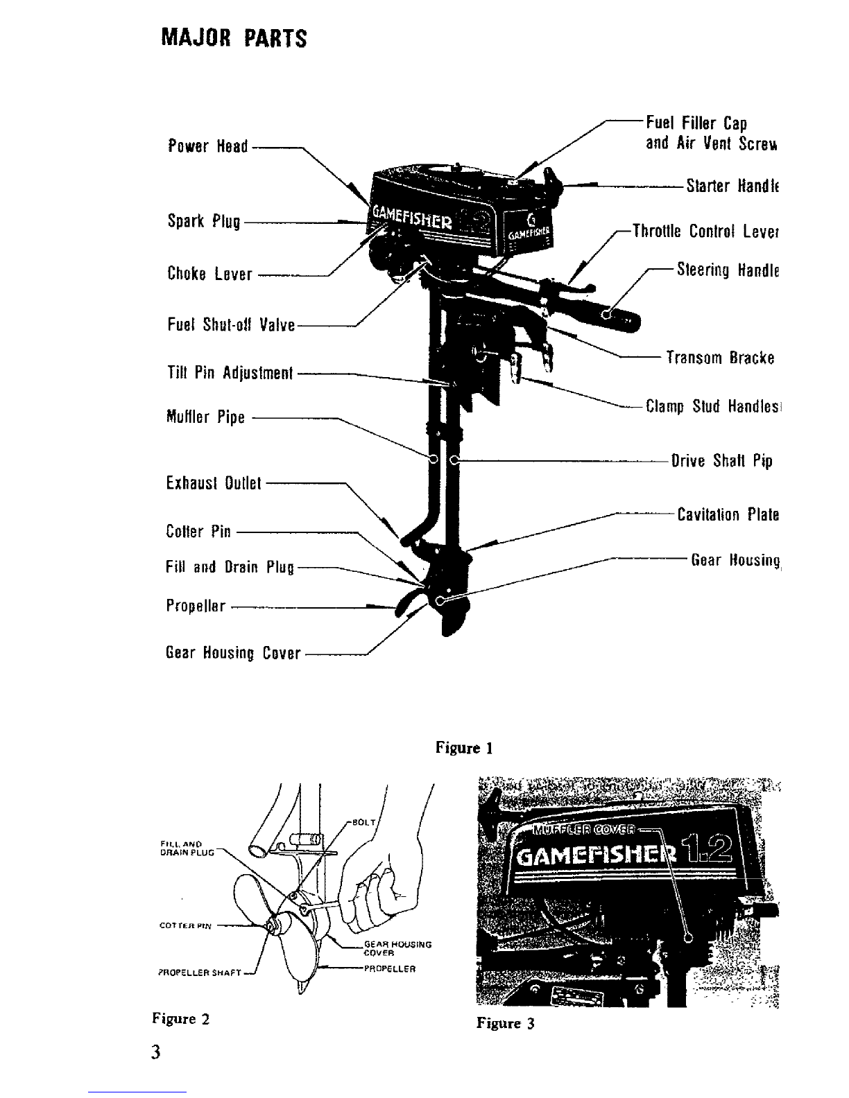
). This outboard motor has special design
features as shown in Figure 1.
}. Your selection of our Marine Products will
provide you with many hours of enjoyable
boating. To assure your complete satisfac-
tion on the in_estment you have just made,
we ask you to read this manual thoroughly
before going afloat. Acquaint yourself with
the particular areas of operation on your
outboard motor as you read the step-by-step
procedures. Keep in mind maximum per-
formance is achieved only when the owner
or operator is completely familiar with the
operatlng instructions.
:, Periodic servicing will be required. It is
recommended that you consult your Sear=
Service Center when service fs necessary.
We will be happy to extend our facilities
and assure prompt service.
_. STEERING HANDLE INSTALLATION
f
iRemove snap pln and washer 5 from steering
handle, screw handle mounting bolt in joint
pipe holder and stop steering handle. Then push
!groove at tip of steering handle against handle
stopper.
::Put washer 5 in over handle mounting bolt and
_insert snap pin.
3, LUBRICATION -- GEAR HOUSING
a. The Gear Housing has been pre-lubricated at
the factory; however, the grease level should
be checked as follows using SAE 90 out-
board motor grease. (See Figure 2).
{1 ) oPrior to initial operation.
{2) After first four (4) hours of use.
(3) Recheck after every fifty {50) hours
running time.
(4) Replace with new lubricant pt the end
of your outboard motor season. This
is important, as it removes any water
from the gear housing and prevents
possible corrosion to internal parts.
b. To Check, Drainer Fill gear housing, follow
these steps:
(1) Position outboard motor upright.
(2) Remove drain plug and washer, then
_nsert nozzle of gear lubricant tube
Into hole.
(3) Squeeze tube until lubricant is forced
out around tube.
[4) Replace plug and washer. Be sure plug
is tightened securely,
(5) To achieve complete drainage of lubri-
cant, remove cotter pin, propeller and
shear pin from propeller shaft, also,
gear housing cover by unscrewing 2
bolts.
C,
(6) When lubricant has completely drained,
replace parts and refill gear housing
using filling procedure above.
For best results, lubricate propeller shaft
with lithium grease every 30 to 60 days.
4. MUFFLER INSPECTION
a. Periodically remove muffler, cover by un-
screwing screws and inspect for carbon
build-up inside the muffler inlet and outlet,
the exhaust port and the combustion
chamber of the cylinder. Excessive carbon
wil! prevent drawing the maximum power
out of the engine. (See Figure 3).
b, Care should be exercised while cleaning
away carbon to prevent scratches to the
surface of the engine components and drop-
ping carbon inside of crankcase.
5. PROLONGED STORAGE
a. To store your outboard motor for pro-
longed storage, prepare outboard as fol-
lows:
(1) See paragraph on stopping procedures.
(Ref, 10)
(2) When removing outboard motor from
boat, allow atl water to drain from
unit.
(3) The outboard mercer should be
mounted on a stand vertically with
power head up for storage.
{4) Pull starter handle slowly until resist-
ance is felt due to compression pres-
sore, then stop. Release starter tension
slowly tO prevent engine from revers-
ing rotation due to compression
pressure. This position will close both
the intake end exhaust ports for
storage.
(5) Drain and fill gear housing as outlined
under Lubrication of Gear Housing.
(Ref. 3)
(6) Wipe exterior completely with fresh
water cloth and then apply light coat-
ing of oil.
b. When starting a new season, always use fresh
gasoline. Last year's gasoline may have
varnish deposits that will plug the carbu-
retor jets, thus requiring a complete over-
haul,
c, To plan for the coming season, we recom-
mend you contact your Sears Service
Center before the new season for any service
repair work required.

OPERATION
6, BOAT MOUNTING
a. Mount the motor on the center of the boat
transom (stern), (See Figure 4).
CAUTION
Hand tighten transom bracket and clamp
stud handles simultaneously. Do not use a
wrench or any other device that would
cause damage to brackets. Occasionally
check to be sure tamp stud handles on
transom mounting bracket are tight.
|Sea Figure 5),
b. To obtain the best performance from your
outboard, the following boat transom speci-
fications are recommended: (Sea Figure 4).
Transom Angle {Sea View 3):
........... 12 to 15 degrees
Transom Height (See View 4):
............... 20 inches
c. The angle of the motor column is easily
adjusted by removing the Hitch Pin and
changing the Tilt Lock Bracket Pin in the
Five (5) different angle position holes
located on either side of the right or _eft
Transom Mounting Brackets. Each angle
position elevates five {bJ degrees, Try
center hole position first. (See Figure 6),
d. To find the correct angle position, make a
test run at full throttle with your usual
loading in the boat. Always stop motor to
change the Tilt Lock Bracket Pin. The cor-
rect angle position w_t! have your boat
traveling with the bow slightly higher than
the stern, but shoutd not porpoise (bow
risesand felts rapidW and contlnuously}. Be
sure Tilt Lock BraCket Pin is always pushed
completely through both Transom Mount-
ing Brackets and Hitch Pin is secured,
WARNING
If the motor corumn is tilted too far out-
ward, the boat is likely to porpoise or
cavitate at full throttle, which can be
dangerous because a cross wind or a wave
could suddenly deflect the boat into a
dangerous turn. Also, if the motor
column is tilted too far inward, the bow
of the boat will dig in, which can be
dangerous when crossing awake or in
rough water. DO not run motor in the
storage position. (,See View fand 2,
Figure 4),
e. Secure motor to boat with Safety Chain.
Chain is not included with motor.
._L_I =_'°)=" 'vl,,,_." -'_.o","*'_
_RIGHT'V|ew2 EVEN KEeL
Vtsw4
FlBure 4 , "
Figure 5
Figure 6
7. STEERING ADJUSTMENT
Tighten steering tension bolt using aspanner
for desired steering effort. (See Figure 6).
iCAUTION j
There is a possibility of losing bolt if
backed out too far.
5

OPERATION
8. 2-CYCLE ENGINE FUEL MIXTURE
Use a good grade of regular gasoline. {See mix-
ing table below.)
CAUTION
Always use BIA certified TC-W oil in the
50:1 ratio. Faiture to do so may result in
excessive spark plug fouling, piston
scoring, or bearing failure. Do not under
any circumstances, use multigrade, such as
! 0W-30, or other automobile oils.
If BIA certified oil is not available, use
an SAE 30 or 40 2-cycle or outboard oil.
We reserve the right to refuse warranty on
parts which are damaged when using
improper fuels or lubricants.
WARNING
Gasoline is hrghly flammable. Always mix
in well ventilated area, Do not fill tank
with motor running, nor near any flame
or while smoking. Be sure vent screws
and filler caps on tanks are finger tighte-
ned when transporting gasoline in the
trunk of your automobile to prevent
explosion.
U.S. Measure
Regular Amount of oil
Gasoline to be added
In Gallons In Pints In O'z'-
1 0.16 2.6
30.48 7.7
FUEL 5 0.80 12.8
MIXING 6 0,96 15.4
TABLE
50"1 Metric Measure
MIXTURE Regular Amount of oil
Gasoline to be added
In Liters In Liter=
1 0.02"
50.10
10 0.20
20 0.40
9. STARTING PROCEDURE (See Figure 7).
a. Open air vent screw located on fuel filler
cap by turning counterclockwise.
b. Open fuel shut-off valve.
c, Open throttle lever to half throttle.
d. Move choke lever to "On" position,
WARNING
When starting outboard, the boat will
move with a sudden burst of speed. Make
sure you are well seated so as not to lose
your balance with a fast start.
FJ_Jure7
Figure 8
e, Pull starter handle slowly until you feel
starter engage. Then pull with rapid
motion and allow the starter cord to
retract slowty. {See Figure 8).
f. After engine has started, gradually move
choke lever to "Off'* position while
warming up the engine.
g. Let engine idte for approximately 3
minutes before moving throttle lever to
"Fast" positson,
10. STOPPING PROCEDURE
To stop engine, move throttle lever to full
"Stop" position. {See Figure 7).
WARNING
In case of an Emergency, the engine can
be stopped by moving the Choke Lever to
Full Choke Position.
If the motor will not be operated for a
persod of time, if st is to be removed from
the boat, or if st is to be tilted up, we
recommend the following practice to
prevent spillage from the carburetor
throat and bowl and to prevent gum
formations in the carburetor during
storage:
1. Close fuet shut-off valve and air
vent screw at fuel filler cap,
2. Allow motor to run at idling speed
untd it stops of its own accord,
indicating the carburetor has run
dry_
6

OPERATION
11. FLOODING
To clear engine of excess fuel, move choke lever
to "Off" position and throttle lever to half
throttle position. PuU recoil starter handle
until engine starts and continues to run.
12, CARBURETOR ADJUSTMENTS
a. Your motor has afixed high speed jet, The
Idle Adjustment has been preset at the
factory. (See Figure 9).
b. Periodically check filter for dirt by unscrew-
ing fuel inlet bolt. (See Figure 9).
13. PROPELLER SHEAR PIN & COTTER
PIN HOLDER
_. The Shear Pin is used for the purpose of
protecting the Drive Train and Gears. The
Shear Pin will not prevent the propeller
from becoming damaged when striking an
under water object. When shear pin is
broken, the engine will continue to run,
however, the propeller will not be rotating.
iCAUTION ]
Stop engine immediately after shearing
pin tO avoid possible damage to the engine,
b. To replace shear pin, shut off motor,
remove cotter pin with needle nose pliers
and slip off propeller. (See Figure 10 & 11).
c. Replace with new shear pin located in shear
pin and cotter pin holder on steering handle,
CARBURETOR
FUEL INLET BOLT
Figure 9
Figure I0
Figure II

OPERATION
14. FLYWHEEL MAGNETO IGNITION
SYSTEM WiTH TRANSISTERIZED
ELECTRONIC IGNITOR
a. The magneto ignition system consists of the
following component parts: Flywheel, Tran-
sisterjzed Electronic ignitor and ignition Coil.
b. Inspect the following if engine fails or is
hard to start:
(I) Spark plug as often as necessary. Be
sure spark plug gap setting is .025"
lO.6mm).
(2) Gasoline fuel supply and fuel shut-
off valve should be Open.
(3) Carburetor being starved of fuel.
c. The correct spark plug for this motor is
NGK BMR6A or Champion RCJ-8.
d. To test ignition system, remove spark
plug and place against bare spot on metal
part of motor away from cylinder soark
plug hole and then pull starter cord several
times, if aspark bridges the plug gap, the
magneto is in good operating condition.
The high tension lead wire must be con-
nected to the plug for this check. If there
is no spark, have the ignition checked at
your Seats Service Center,
15, REMOVING MOTOR FROM BOAT
a, Always tilt motor by lifting on rear of
shroud. DO NOT PUSH DOWN ON THE
STEERING HANDLE. When removing the
motor from the boat, raise the outboard in
upward direction until the propeller clears
the transom.
Hold the motor upright long enough t_
allow all water to drain from the exhaust_
pipe. When you find it difficult to hold_
the motor upright, tighten the Center_
Bolt increasingly for desired effort. (See_
Figure 131. j
WARNING
Although the engine is air cooled, it is
possible to burn your hands on the engine
b;ock and upper portion of the column.
DO not touch.
b= It may be necessary to rotate the motor to
one side before tilting the motor on the
transom to remove leg from the water when
installed on boats with thick transoms.
c. Always carry outboard with the engine
above the lower unit to prevent moisture
from entering the engine through the
exhaust ports.
CENTER BOLT
Figure 13 WARNING
If the motor will not be operated for a
period of time, if it is to be removed
from the boat, or if it is to be tilted up,
we recommend the following practice to
prevent spillage from the carburetor
throat and bowl and to prevent gum
formations in the carburetor during
storage:
1. Close fuel shut-off valve and air vent
screw at fuel filler cap.
2, Allow motor to run at idling speed
until it stops of its own accord, indi-
cating the carburetor has run dry.
16. SALT WATER OPERATION
To materially increase the life of att exposed
parts and decorative finishes, follow the steps
indicated below.
a, Always tilt your motor out of the water
when not in use.
b. Never leave the lower unit in salt water
overnight.
c. Wipe exterior completely with fresh water
cloth and then apply light coating of oil,
d. Lubricate propeller shaft occasionally with
a waterproof type of lubricant (Lithium
Grease), thus enabling the propeller to be
removed easily.
e. it is good practice when operating in satt
water to inspect your motor deity and to
apply afight coating of grease to any
part or area that shows evidence of cor-
rosion or rust.
f. Always remove motor from boat ver-
tically, allowing water to drain from column
before tilting the motor.
8

TROUBLESHOOTING CHECK LIST
"Take your outboard motor Into any one of over
2000 SearsService Unite,
X X Fuel Tank Empty "
X X Fue! Shut-Off Valve Ciosed
XX XXFuel Line Kinked or Pinched "
X X XX Vent Screw on' Fuel Tank Filter Cap C'lo_d
X x x x Carburetor PassagesCloggedor Dirty *
X X X X X Incorrect Fuel-Oil Mixture
X X X X X Carburetor Out of Adjustment
X X Engine Flooded
X"" X X. ,. X X' Wrong Type Spark Plug
X X X X X Defective or Fouled Spark Piug
X X Defecti_ Magneto *
X Spark Does Not Jump Spark Plug Gap J. *
'" X'" Engine Out of Tim;" "
Xx X X Transisterized Electronic Ignitor out of order "
X X X X X Weak Ignition Coii
X X Spark Plug LeadWire Not Secured ....
X X Frayed or Cracked Lead Wire Insufation
X X Disconnected. Grounde_d'0r Loom Wiring in Electricai 'SyStem *
X Propeller Bound by Foreign Objects (F!shing L_ne.Weeds. Etc.) .,
X High Tension Lead-Salt Water Build Up
9
IMPORTANT INFORMATION
MODEL NUMBER: 298,586131
SERIAL NUMBER
DATE OF PURCHASE
INSURE YOUR ENGINE
Many insurance companies including Allstate
Insurance offer protection contraCts for your
boat and outboard engine. Insurance covering
your own equipment against damage, theft,
etc., as well as liability insurance for property
damage and personal injuw to others is availa-
ble. It would be wise to contact your insurance
agent for further information about adequate
protection.
IDENTIFICATION PLATE
\
OPERATING LOG
DATE NO. HR_ USED GALS. FUEL USED DATE
FNO. HRS. USED GALS, FUEL USED

REPLACEMENTPARTS
FOR
MODEL No.298.586131
20

FIG.1 ENGINE
35__71 °74
55 2
,__1 2°
i_--9S
_----7o
--18
]!

FIG.1 ENGINE
REENo.
1-002
1-003
1-004
1-00S
1-007
1-008
1-009
1-010
1-011
1-012
1-013
1-014
1-015
1-01,7
1-018
1-020
1-025
1-026
1-027
1-030
1-031
1-032
1-033
1-034
1-035
1-038
1-039
1-040
1-041
1-042
1-043
1-044
1-053
1-055
1-067
1-068
1-070
1-071
1-074
1-075
1-078
1-079
1-080
1-089
1-095
P.P.No.
157-04000-900
018-00546-200
002-00500-804
017-00501-202!
041-00000-210
039-00000-20!
031-00500-200
037-00000-200
046-00557-801
068-02000-200
070-02401-201
999-61600-200
999-66152-500
038-00000-200
072-00586-900
159-21401-871
999-61620-100
999-66122-821
090-00501-202
167-20759-800
178-00810-801
155-21708-900
I12-00501-203
202-10200-201
198-I1600-800
065-00000-200
066-00000-200
790-00601-203
992-01050-011
788-00601-203
822-00801-200
793-10200-201
070-00601-201
256-01046-200
990-11060-222
992-10060-042
990-I1040-182
990-11040-081
990-11050-202
992-10050-042
990-11050-202
992-10050-042
992-10060-042
990-11080-182
992-10040-012
PARTS NAME
SPARK PLUG CAP ASS'Y
SPARK PLUG BHR6A
CYLINDER COHP.
CYLINDER GASKET
PISTOH RIHG
PISTON PIN CIRCLIP
PISTOH
PISTOH PIN 9X24
CRANK SHAFT COHP.
WOOD-RUFF KEY 3XI3X5
CRANK SSAFT WASHER 15,2X22
BALL BEARING .8002
OIL SEAL 15257
>ISTON PIN BHSHIHG
CRAHK CASE ASS'Y
IGHITOR TTI-1E
BALL BEARIHG _6201
OIL SEAL 12287
CRANK CASE GASKET
IGNITIOH COIL COUP.
STOP CORD COHP.
NAGNETO ROTOR ASS'Y
FAN CASE
iGROHHET
CORD CLANP COHP.
FLYWHEEL WASHER
FLYWHEEL HUT 12
STARTER PAWL SPRING
WASHER 5
STARTER PAVL
STARTER PAWL SHIH O.BT
STEP BOLT
CRANK SHAFT WASHER 12.2X18
SPARK PLUG RUBBER COVER B
SCREW 6X22
S.WASUER 6
SCREW 4X18
;CREW 4X6
SCREW 5X20
S.VASUER 5
SCREW 5X20
S.WASNER 5
S.WASHER 6
SCREW BX18
S.WASHER 4
Q'ty
1
I
1
1
2
2
1
t
1
1
1
1
1
1
1
1
1
I
1
1
1
I
1
I
I
1
l
2
2
',2
2
2
2
1
3
3
2
I
2
2
3
3
3
3
2
12

FI_.2 TANK, CLUTCH & MUFFLER
SEE FIG.
38
2640 _4,
41 24
23
25 27-
t9 20
22
31 37 36
]3

FIG.2 ENGINE COVER & MUFFLER
RERNo.
2-002
2-003
2-004
2-005
2-012
2-015
2-017
2-019
2-O20
2-022
2-023
2-024
2-025
2-026
2-027
2-028
2-029
2-030
2-031
2-032
2-033
2-034
2-035
2-036
2-037
2-038
2-039
2-040
2-04t
2-042 •
2-043
2-044
2-045
2-100
2-101
2-102
2-103
-P.P.No.
595= 51oo- oo2
300-35108-200
_600-35100-203
401-35100-204
5_2-00750-900
700-07105-180
680-00618-201
403-00001-200
393-00004-201
410-00517-900
737-00531-201
716-00568-200
?37-00517-200
717-00568-200
221-35100-200
228-35100-201
220-35100-203
225-35100-203
227-35100-203
990-11040-252
992-10040-042
990_11050-162
992-10050-042
990-11040-252
992-10040-042
g90-11040-202
992-10040-042
990-11050-202
992-10050-042
990-11050-122
992-10050-042
990-11060-222
992-10060-042
330-35118-200
331-35118-200
906-35_18-200
336-35118-200
PARTS NAME
TAlKCAP*ASS' "
EHGINE COVER
!TAH[ SUPPORT KIHG
FUEL TAHK
PET-COCK ASS'Y
_PHEL PIPE 7XlO,5X180
iCLIP
INLET HAHIFOLD GASKET
IHLET HAHIFOLP
!AIR CLEAHER ASS'Y
MUFFLER GASKET
HUFFLER BODY A
HUFFLER GASKET
HUFFLER BODY B
HgFFLER PIPE GASKET
HUPFLEK PIPE STAY A
HOFFLER PIPE
HUFFLER PIPE STAY
HUFFLER PIPE STAY B
SCREW 4X25
S,VASHER 4
SCREW 5X16
S.WASHER 5
SCREW 4X25
S.VASHER 4
SCREN 4X20
S,WASHER 4
SCREW 5X20
S.NASHER 5
SCREW 5X12
!S.WASHER 5
SCREW 6X22
S.WASHER 6
RIGHT SIDE HARK
LEFT SIDE HARK
iHAHE PLATE
STAKTER NARK
[O'ty
1
I
I
I
1
I
2
1
I
1
1
1
I
1
1
1
1
I
I
3
3
2
2
2
2
4
4
2
2
2
2
l
l
1
I
I
1
14

FIG.3 RECOIL STARTER
0 u
5
15
REENo. P.P.No. NAME
3-000
3-001
3-002
3-003
3-004
3-005
3-006
3-007
3_008
3-009
3-010
3-011
3-012
3-013
3-014
3-015
3-016
3-017
756-00537-900
!772-00537-200
774-04015-204
!779-01006-201
776-01006-207
'783-00517=200
780-00601-201
;785-10207-201
i773-00100-204
814-00500-200
990-11050-122
992-I0050-042
992-01060-041
992-10060-042
991-41060-022
782-00546*200
833-10207-200
992-01040-01I
PARTS
,,i. ,, .r,,,,j
RECOIL STARTER ASS'Y
RECOIL STARTER BODY
STARTER ROPE REEL
RECOIL SPRIHG
PULLEY SHAFT
STARTER ROPE 3.5X1300
ROPE GUIDE
STARTER HAHDLE
POLLEY SHAFT/OUTER
STARTER PULLEY SHIH
SCREW 5X12
S.WASHER 5
WASHER 6
S.VASHER 6
CAP NUT 6
ROPE RECEIVE
STARTER HANDLE CAP
WASHER4
IS-
O'ty
1
1
I
1
1
]
]
1
1
1
2
2
I
1
t
1
1
!

FIG.4 CARBURETOR
0--
0
6_
8,0 28
/a
RERNo. P.P.No.
.L.
4-000
4-001
4-002
4-004
4-005
4-006
4-007
4-008
4-OOg
4-010
4-011
4-012
4-013
4-014
4-015
4-016
4-017
4-018
4-019
4-020
4-021
4-022
4-023
4-024
4-025
4-026
4-027
4-028
a
#
- 23
----24
• 26
455-21602-901
560-20445-200
597-20110-200
595-21303-200
594-20110-200
6!9-20110-200
592-2002T-930
593-20400-200
591-2003T-200
561-20445-900
571-20400-200
622-20110-200
623-21700-200
994-34040-100
550+21700-200
602-20445-200
603-20110-200
628-20202-200
605-21700-200
598-2004T-900
599-2001T-580
604-20110-200,
607-20110-200
606-20202-200
629-20445-200
990-11040-05t
500-21700-200
50t-21700-900
PARTS NAME
i
CARBURETOR A'SS'Y
RUBBER CAP
CABLE ADJUSTER
BODY CAP
THROTTLE VALVE SPRING
THROTTLE SPRING RECEIVE
JET HEEDLE ASS'Y 004
JET NEEDLE CLIP
TBRDTTLE VALVE 0.5XI.5
BODY BAND ASS'Y
FLANGE GASKET
ADJUSTER SCREW
ADJUST SPRING
SCREW 4XlO/S
O-RING
NEEDLE SEAT
NEEDLE VALVE
FLOAT ARM
FLOAT ARM PIN
HEEDLE JET 2090
MAIN JET _58
FLOAT
FLOAT CHAHBER GASKET
FLOAT CHAMBER W/THREAD
DRAIN SCREW GASKET
SCREW 4X5
FUEL INLET GASKET
FUEL INLET BOLT ASS'Y
iQ'ty+
1
]
1
1
1
]
1
]
1
I
1
I
1
2
!
1
i
1
1
!!
l
1
i]
!
2
I
16

FIG.5 HANDLE &BRACKET
35
1_ I1
9
34 _
6
7
3
12
13
15
14
16
I
23
25
39
26
27
28
21
22
20
I?

FIG.5 HANDLE & BRACKET
RERNo. P.P.No. PARTS NAME O'ty
8SS-OOS_-SOO'TNR_TTLEVZRE_OHP.
870-00569-900 THROTTLE LgVER ASS'¥
5-001
5-002
5-003
5-004
5-005
5-006
5-007
5-008
5-009
5-010
5-01I
5-012
5-013
5-014
5-015
5-016
5-017
5-018
5-019
5-020
5-021
5-022
5-023
5-024
5-025
5-026
5-027
5-028
5-029
5-030
5-031
5-032
5_033
5-034
5-035
5-036
5-037
5-038
5-039
5-040
145-35118-200
990-11060-182
992-10060-04_
990-21060-302
992-10060-042
160-35118-901
163-35118-200
992-10060-042
162-35118-200,
079-35100-801
150-35109-200
115-35500-204
990-21060-102
I31-3511B-200
134-35109-201
990-21050-302
992-10050-042
113-35109-200
990-11050-122
992-10050-042
108-35501-200
123-35500,-201
129-35100-200
107-35118-801
106-35119-801
990-21060-752
991-41060-022
992-10060-042
992-01060-04!
992-01050-041
106-35118-200
161-35118-200
990-11050-202:
991-01050-021
021-35100-201
012-35100-201
01!-35100-200
910-00562-201
JOINT PIPE HOLDER
_SCREW OX18
S.WASHER 0
BOLT 6X30
!S.WASHER 6
STEERING HAHDLE ASS'Y
HANDLE HOUNTING BOLT
S.WASHER 6
HANDLE WASHER
ADAPTER COHP.
ITHRUST WASHER
BRACKET
!BOLT 6XI0
THRUST BRACKET
ADJUSTIHG PLATE
BOLT 5X30
S.WASHER 5
BRACKET PIH HOLDER
[SCREW5X12
S.WASHER 5
tCLA_P BRACKET BUSHIHG
BRACKET PIN S
BRACKET PIH STOPPER A
CLAMP BRACKET B COHP.
CLAHP BRACKET A COHP.
BOLT BXT5
CAP NUT 6
S.WASHER 6
WASHER 6
WASHER 5
SNAP PIN
HANDLE STOPPER
SCREW 5X20
NUT 5
PIN HOLDER
SHEAR PIH
COTTER P[H
THROTTLE LEVER HARK
I
I
1
3
3
1
1
1
1
1
1
1
1
1
1
4
t
t
I
1
4
4
2
1
1
tI
1
1
I
I
I
1
1
1
!
1
2
2
1
18

FIG.6 DRIVE SHAFT PIPE & GEAR CASE
31
32
2°
[9
Table of contents
Other Sears Outboard Motor manuals