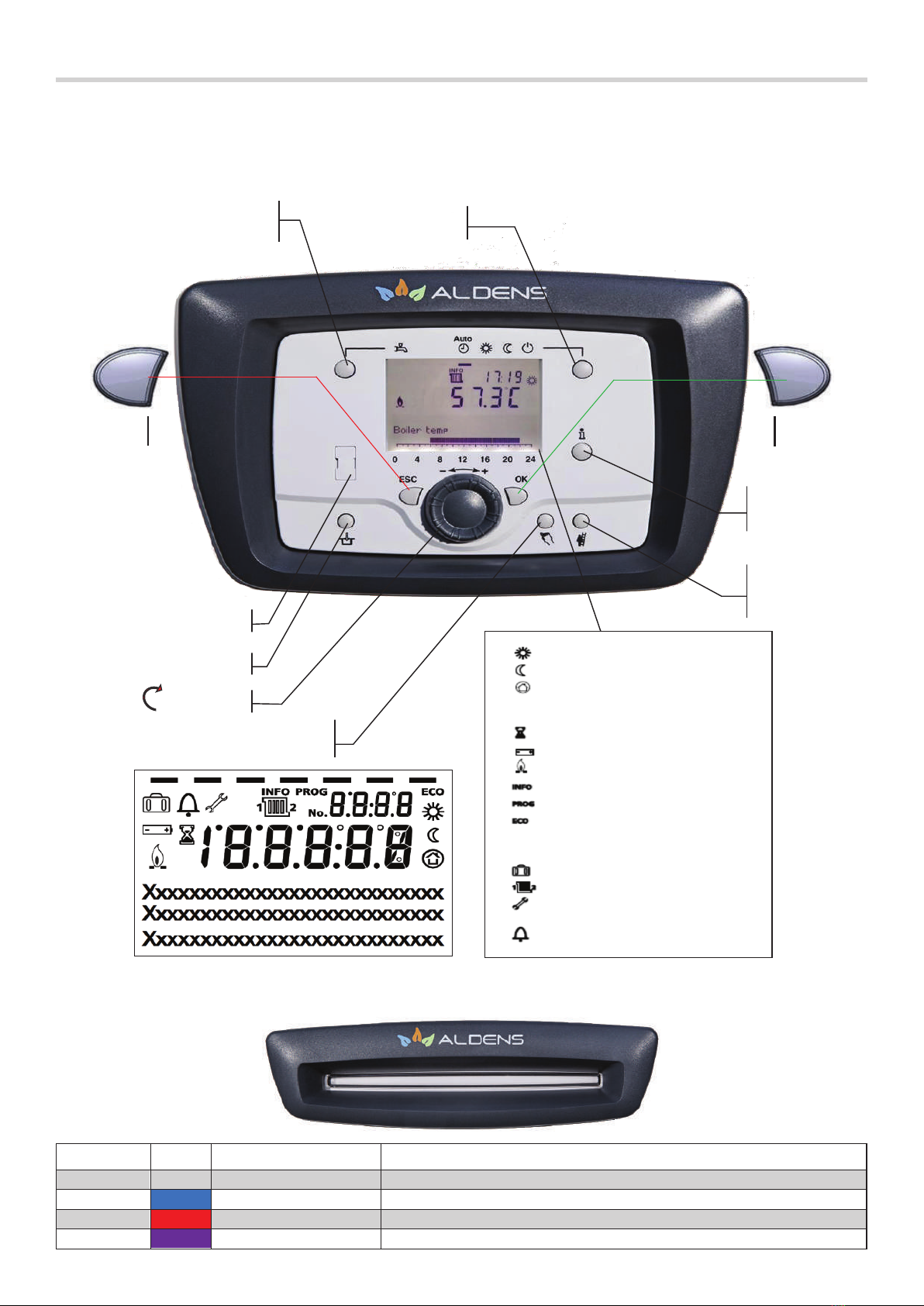
Alarko ALDENS 65 User manual

ALDENS 65, 85, 105, 130, 150 L/T
USER MANUAL

Code No: A.4.1.14i Publishing Date: 180121
Revision Date: 180121

ALDENS 65, 85, 105, 130, 150 L/T
USER MANUAL

4
CONTENTS
1. Introduction 7
1.1. General Warnings / Warranty Issues 7
1.2. Product Conformity 8
2.1. Boiler Panel and Human Machine Interface (Master Boiler) 9
2.3. Product Declerations of Conformity (ErP Directive) 11
2.4. System General View / Sub-System and Components 14
2.4.1. ALDENS 65 L/T 14
2.4.2. ALDENS 85 L/T, ALDENS 105 L/T , ALDENS 130 L/T, ALDENS 150 L/T 15
2.5. Read Before Installation 16
2.5.1. Content of Shipping 16
2.5.2. Additional Accesories 17
2.5.3. Boiler and Sanitary Connection Dimensions (Same for Master and Slave Boilers) 21
2.5.4. Installed Cascade System Dimensions 22
2.5.5. Sanitary Needs For a Long Boiler Life and Proper Operation 22
2.5.6. Minimum Free Space Dimensions To Be Left Between the Boiler and the Walls 23
2.5.7. Device Mechanical Circuitry (Hydraulic, Gas, Exhaust) 25
2.6. Water Management 26
2.6.1. Circulating Pump Technical Properties and Characteristic Curves 26
2.6.2. Water Pressure Supervision 29
2.6.3. Water Fill / Drainage From The Circuit 31
2.6.4. Hardness and Conductivity of Water, Fur Layer 31
3.1. General and Safety Warnings 33
3.1.1. Informations and Safety Warnings About the Circuit 33
3.1.2. Safety Warnings and useful Information About the Heat Exchanger, Fan and the Venturi 35
3.1.2.1.
Safety Warnings and Useful Information About the Heat Exchanger, Fan and the Venturi
35
3.1.2.2. Heat Exchanger Hanging System (Patented– PT2014/15542) 38

5
3.1.2.3. Limit Thermostat 39
3.1.2.4. Thermal Fuse 40
3.2. Unpacking The Boiler 41
3.3. Mounting On The Wall and The Hanging System 42
3.4. Electrical Wiring Diagram and DHW Circuitry 42
3.5. Flue Pipe System and Components 47
3.5.1. Standard Chimney Types 48
3.5.2. Flue / Fresh Air Piping Accesories 51
3.6. DHW Tank, Solar Collector, Direct and Mixing Circuits, System Examples 53
3.7. Quantity of Boilers, Extension Module and Sensor Quantities 56
4. Comissioning, Adjustments and Maintenance 58
4.1. Temperature Settings And Mode Selection On The Main Panel 58
4.1.1. Monitoring and Setting Parameters 58
4.1.2. Language Selection 59
4.1.3. Setting The Comfort Temperature 59
4.1.4. Boiler Operation Mode Selection 61
4.2. Accessing The Menus And Parameters 62
4.3. Time Program Settings 63
4.4. Frost Protection Settings 66
4.5. Heating Curve 67
4.6. Important And Practical Enduser Parameters 68
4.7. Maintenance Issues 68
4.8. System Monitoring and Audition with the Web Server via Local Area Network or Internet 69
5. Fault Codes 70

6

7
1. Introduction
1.1. General Warnings / Warranty Issues
Please refer and use the information in the content of this manual textbook. Obey the
instructions, warnings and advices. The warnings and instructions are the matter of your and
your device’s safety. The sections of this manual textbook are mostly in the order of the start of
comissioning with the unpacking of the device towards decomissioning and disassembling.
The neutral keeping position of your device unless it is hanged on a wall or a hanging structure is
horizontal with front side (the side including the control panel, on which the ALDENS LOGO and the
word “ALDENS” is also written) directed upwards. Especially please refer to this information in case
of heat exchanger assembling or disassembling.
As factory setting, ALDENS boilers are set to operate with natural gas fuel. Whether if LPG will be
used as fuel for a single or a cascade system, all the boilers should be adapted to operate with LPG
fuel. For establishing this adaptation please refer to Alarko Carrier authorized services.
Warranty
Your device’s warranty is valid for only the case that it has been comissioned appropriate with this
The period for ALDENS devices is 2 years.
Natural gas is an environment friendly fuel. Your device is a high valued State-of-the-Art and are
equipped with the highest technology safety precautions.

8
compliance with the relevant standards.
with the following standards:
2009/142/EC – GAS APPLIANCES DIRECTIVE
92/42/EEC – EFFICIENCY REQUIREMENTS FOR NEW HOT-WATER BOILERS FIRED WITH
LIQUID OR GASEOUS FUELS
2014/30/EU – ELECTROMAGNETIC COMPATIBILITY (EMC) DIRECTIVE
2014/35/EU – LOW VOLTAGE DIRECTIVE (LVD)
2006/42/EC – THE MACHINERY DIRECTIVE (MD)
2010/30/EU – LABELLING DIRECTIVE : Commision Delegated Regulation (EU) No: 811/2013 of 18
February 2013 supplementing directive 2010/30/EU of the European Parliament and of the Council
with regard to the energy labelling of space heaters, combination heaters, packages of space heater,
temperature control and solar device and packages of combination heater, temperature control and
solar device.
2009/125/EC – ECODESIGN DIRECTIVE : Commission Regulation (EU) No: 813/2013 of August
2013 implementing directive 2009/125/EC of the European Parliament and of the Council with regard
to ecodesign requirements for space heaters and combination heaters.
Standards:
EN 15502-1:2012+A1:2015 - Gas-red heating boilers Part 1: General requirements and tests
EN 15502-2-1:2013 - Gas-red central heating boilers Part 2: Specic standard for type C
appliances and type B2, B3 and B5 appliances of a nominal heat input not exceeding 1 000 kW

9
Panel light
Appearance
Explanation
No light
-
Boiler standby
Blue
Permanent Burner operation
Red
Blinking
Boiler error
Magenta
Temporary continuous
At first energizing the boiler with electricity or while parameters loading.
Heating to Comfort setpoint
Heating to Reduced setpoint
Heating to frost protection setpoint
Process running - please wait
Change battery
Burner operation
Info level activated
Programming activated
Heating temporarily switched off
ECO function active
Holiday function active
Reference to heating circuit
Maintenance / special operation
Error messages
Selection of Domestic Hot
Water (DHW) Heating Heating Mode Selection
Displaying
information
Chimney sweep
function
Reset
Manual operation
(Additional feature : Aereation prevention)
Selection wheel
Service socket
ESC OK
Quit Confirm

10
PROPERTY
UNIT
ALDENS 65
ALDENS 85
ALDENS 105
ALDENS 130
ALDENS 150
Types Proper for Cascade Setup
Master (L)
Master (L)
Master (L)
Master (L)
Master (L)
Slave (T)
Slave (T)
Slave (T)
Slave (T)
Slave (T)
Fuel
Natural Gas (G20) +
LPG (G31)
Natural Gas (G20) +
LPG (G31)
Natural Gas (G20) +
LPG (G31)
Natural Gas (G20) +
LPG (G31)
Natural Gas (G20) +
LPG (G31)
Upstream Pressure (Inlet)
mbar
21
21
21
21
21
Fuel Consumption @ Maximum Load
m
3
/h
6,87
8,83
11,17
13,28
15,11
Fuel Consumption @ Minimum Load
m
3
/h
1,35
1,76
2,16
2,68
3,07
Technical Parameters wrt. ErP Directive
P
n
–Rated Heat Output
kW
64
85
105
125
145
P
4
–Useful Heat Output @ Max L.–(80/60
o
C)
kW
61,6
81,2
101,3
120,0
143,7
P
1
–Useful Heat Output @ Part L. –(50/30
o
C)
kW
20,7
25,3
34,2
41,0
46,0
η
s
–Seasonal Space Heating Energy Efficiency
%
91
93
92
94
91
η
4
–Useful Efficiency @ Max L. –(80/60
o
C)
%
87,3
86
86,9
86,4
89,2
η
1
–Useful Efficiency @ Part L. –(50/30
o
C)
%
97,7
97,5
97,7
98,4
96,7
P
stby
–Standby Heat Losses
W
68
80
80
117
121
P
ign
–Ignition Burner Energy Consumption
kW
1,75
2,92
1,97
1,94
2,16
L
wA
–Sound Power Level (Indoors)
dB
58,8
61,9
63,8
66,3
67,4
NOx –Emissions of Nitrogen Oxides
mg/kWh
44,2
46,2
41,3
55,2
54,6
NOx Class
-
6
6
6
6
6
Boiler Heat Output / Efficiency
Maximum / Minimum Output (50/30
o
C)
kW
67,2 / 13,4
90,1 / 18,5
109,0 / 21,7
135,1 / 27,3
153,9 / 30,7
Maximum (P
4
) / Minimum Output (80/60
o
C)
kW
61,6 / 12,0
81,2 / 16,5
101,3 / 19,5
120,0 / 24,5
143,7 / 28,2
Output @ Fan Ignition RPM
kW
27,5
44,3
52,2
56,8
60,1
Efficiency (50/30
o
C – Max./ Min. Load)
%
105,8 / 107,3
106,0 / 108,6
103,9 / 108,3
108,1 / 109,0
106,2 / 105,8
Efficiency (80/60
o
C – Max./ Min. Load)
%
97,0 / 95,8
95,6 / 97,2
96,5 / 97,6
96,0 / 97,8
99,1 / 97,2
Maximum Backpressures / Fluegas Flowrate
Backpressure (Max. / Min. Load)
Pa
137 / 79
210 / 105
253 / 90
256 / 70
282 / 87
Backpressure (Ignition)
Pa
106
116
122
106
118
Fluegas Flowrate (Maximum Load - 50/30
o
C)
g/s
24,7
34,9
44,6
51,8
58,2
Fluegas Flowrate (Minimum Load - 50/30
o
C)
g/s
4,9
7,0
8,6
10,5
11,8
Fluegas Flowrate (Maximum Load - 80/60
o
C)
g/s
30,0
37,7
48,4
57,1
64,2
Fluegas Flowrate (Minimum Load - 80/60
o
C)
g/s
5,9
7,5
9,4
11,5
13,0
CO
2
Conc. (Max. / Min Load) –(50/30
o
C)
%
9,12 / 9,12
9,0 / 9,0
9,05 / 9,16
9,13 / 9,23
9,27 / 9,06
Flue Temp. (Max. / Min. Load) –(50/30
o
C)
o
C
63,3 / 40,4
51,6 / 34,2
64,8 / 32,1
58,0 / 31,7
54,4 / 43,8
Flue Temp. (Max. / Min. Load) –(80/60
o
C)
o
C
82,7 / 64,1
70,0 / 62,7
78,0 / 60,8
74,8 / 60,5
74,5 / 65,0
Electrical Properties
Electrical Input (Voltage/Frequency)
VAC/Hz
230 / 50
230 / 50
230 / 50
230 / 50
230 / 50
Electrical Fuse
A
6,3
6,3
6,3
6,3
6,3
Electrical Consumption in Standby
W
2,7
2,7
2,7
2,7
2,7
Electrical Consumption –Max. / Min. Load
W
91,8 / 18,7
109,0 / 14,7
131,1 / 16,9
205,7 / 18,8
284,2 / 21,0
Installations / Connections
Gas Connection
inch
¾”
¾”
¾”
¾”
¾”
Heating Circuit (Inlet / Outlet)
inch
1”
1 ¼”
1 ¼”
1 ¼”
1 ¼”
DHW Circuit (Inlet / Outlet)
inch
1”
1 ¼”
1 ¼”
1 ¼”
1 ¼”
Maximum Water Pressure of Operation
bar
4,5
6
6
6
6
Minimum Water Pressure of Operation
bar
1
1
1
1
1
Boiler Hydraulic Loss –Max Load (50/30
o
C)
mWC
5,4
2,9
4,4
5,0
5,0
Boiler Hydraulic Loss –Max Load (80/60
o
C)
mWC
4,6
2,5
3,7
3,9
4,5
Water Flowrate @ Max. Load - (50/30
o
C)
m3/h
2,8
3,7
4,5
5,6
6,3
Boiler water fill up volume
lt
3,4
6,6
6,6
8,2
10,1
General Properties
Boiler Net Dimensions (W x D x H)
mm
493 x 540 x 627
493 x 540 x 797
493 x 540 x 797
493 x 540 x 797
493 x 635 x 797
Packaged Dimensions (W x D x H)
mm
565 x 740 x 760
565 x 910 x 760
565 x 910 x 760
565 x 910 x 760
565 x 910 x 850
Boiler Weight (Empty / Full)
kg
54,6 / 58
68,7 / 75,3
68,7 / 75,3
75,2 / 83,4
88,6 / 98,7
Packaged Weight
kg
58,6
72,7
72,7
79,2
92,6
Chimney Pipe Diameters (exhaust/air intake)
mm
100 / 150
100 / 150
100 / 150
100 / 150
100 / 150
Type
-
Hermetic / full
condensing
Hermetic / full
condensing
Hermetic / full
condensing
Hermetic / full
condensing
Hermetic / full
condensing
Control Panel
-
Electronic and Push
Button
Electronic and Push
Button
Electronic and Push
Button
Electronic and Push
Button
Electronic and Push
Button
Ignition System
-
Electronic
Electronic
Electronic
Electronic
Electronic
Fault Detection and Warning
-
YES - error code on
screen
YES - error code on
screen
YES - error code on
screen
YES - error code on
screen
YES - error code on
screen
Floor Heating Application
-
YES
YES
YES
YES
YES
Cascade Operation
-
256 items
maximum
256 items
maximum
256 items
maximum
256 items
maximum
256 items
maximum
Frost Protection
-
YES
YES
YES
YES
YES
Time Programming / Holiday Mode
-
YES
YES
YES
YES
YES
Parametric Tuning Hardware
-
User monitor HMI
/ PC
User monitor HMI
/ PC
User monitor HMI
/ PC
User monitor HMI
/ PC
User monitor HMI
/ PC

11
YES
NO
NO
NO NO
NO
Item Symbol Value Unit Item Symbol Value Unit
Rated heat output
P
n
64 kW Seasonal space heating energy efficiency η
s
91 %
At nominal heat output and high-temperature
regime (*) P461,6 kW At nominal heat output and high-temperature
regime (*) η487,3 %
At 30% of nominal heat output and low-
temperature regime (**) P120,7 kW At 30% of nominal heat output and low-
temperature regime (**) η197,7 %
At full load elmax 92 W Standby heat losses Pstby 0,068 kW
At part load
el
min
17 WIgnition burner energy consumption P
ign
1,75 kW
In standby mode
P
SB 3 W Sound power level, indoors
L
WA 58,8 dB
Emissions of nitrogen oxides NOx 44,2 mg/kWh
Contact information
(*) High temperature regime means 60 ⁰C on return and 80 ⁰C on flow.
Equipped with a supplementary heating system:
Auxiliary electricity consumption
(**) Low temperature regime means 30 ⁰C for condensing boilers, 37 ⁰C for low-temperature boilers and 50 ⁰C for other appliances on return temperature.
B11 Boiler/s:
Cogeneration Space Heater:
Other items
ALARKO CARRIER SAN. TİC. A.Ş., GOSB - Gebze O.S.B., Şahabettin Bilgisu Cad., 41400, Gebze/Kocaeli/Turkey
Combination Heater:
For boiler space heaters and boiler combination heaters: Useful heat output For boiler space heaters and boiler combination heaters: Useful efficiency
Model/s: ALDENS 65 L/T
Condensing Boiler/s:
Low Temperature Boiler/s:
dB
2019 811/2013
kW
A+++
A++
A
A
B
C
D
+
A
San. ve Tic. A.S.
Alarko Carrier
ALDENS 65
64
59
Product Fiche for ALDENS 65 L/T
Seasonal space heating energy efficiency class A
Rated heat output kW 64
Seasonal space heating energy efficiency % 91
Sound power level LWA indoors dB 58,8

12
YES
NO
NO
NO NO
NO
Item Symbol Value Unit Item Symbol Value Unit
Rated heat output
P
n85 kW Seasonal space heating energy efficiency
η
s93 %
At nominal heat output and high-temperature
regime (*) P481,2 kW At nominal heat output and high-temperature
regime (*) η486 %
At 30% of nominal heat output and low-
temperature regime (**) P125,3 kW At 30% of nominal heat output and low-
temperature regime (**) η197,5 %
At full load elmax 109 W Standby heat losses Pstby 0,08 kW
At part load
el
min 18 WIgnition burner energy consumption
P
ign 2,92 kW
In standby mode
PSB
3 W Sound power level, indoors
LWA
61,9 dB
Emissions of nitrogen oxides NOx 46,2 mg/kWh
Contact information
Model/s: ALDENS 85 L/T
Condensing Boiler/s:
Low Temperature Boiler/s:
B11 Boiler/s:
Cogeneration Space Heater: Equipped with a supplementary heating system:
Combination Heater:
(*) High temperature regime means 60 ⁰C on return and 80 ⁰C on flow.
(**) Low temperature regime means 30 ⁰C for condensing boilers, 37 ⁰C for low-temperature boilers and 50 ⁰C for other appliances on return temperature.
For boiler space heaters and boiler combination heaters: Useful heat output For boiler space heaters and boiler combination heaters: Useful efficiency
Auxiliary electricity consumption Other items
ALARKO CARRIER SAN. TİC. A.Ş., GOSB - Gebze O.S.B., Şahabettin Bilgisu Cad., 41400, Gebze/Kocaeli/Turkey
YES
NO
NO
NO NO
NO
Item Symbol Value Unit Item Symbol Value Unit
Rated heat output
P
n
105 kW Seasonal space heating energy efficiency η
s
92 %
At nominal heat output and high-temperature
regime (*) P4101,3 kW At nominal heat output and high-temperature
regime (*) η486,9 %
At 30% of nominal heat output and low-
temperature regime (**) P134,2 kW At 30% of nominal heat output and low-
temperature regime (**) η197,7 %
At full load
el
max
131 W Standby heat losses P
stby
0,08 kW
At part load
elmin
21 WIgnition burner energy consumption
Pign
1,966 kW
In standby mode PSB 3 W Sound power level, indoors LWA 63,8 dB
Emissions of nitrogen oxides NOx 41,3 mg/kWh
Contact information
Model/s: ALDENS 105 L/T
Condensing Boiler/s:
Low Temperature Boiler/s:
B11 Boiler/s:
Cogeneration Space Heater:
Other items
ALARKO CARRIER SAN. TİC. A.Ş., GOSB - Gebze O.S.B., Şahabettin Bilgisu Cad., 41400, Gebze/Kocaeli/Turkey
Combination Heater:
For boiler space heaters and boiler combination heaters: Useful heat output For boiler space heaters and boiler combination heaters: Useful efficiency
(*) High temperature regime means 60 ⁰C on return and 80 ⁰C on flow.
Equipped with a supplementary heating system:
Auxiliary electricity consumption
(**) Low temperature regime means 30 ⁰C for condensing boilers, 37 ⁰C for low-temperature boilers and 50 ⁰C for other appliances on return temperature.

13
YES
NO
NO
NO NO
NO
Item Symbol Value Unit Item Symbol Value Unit
Rated heat output
P
n125 kW Seasonal space heating energy efficiency
η
s94 %
At nominal heat output and high-temperature
regime (*) P4120 kW At nominal heat output and high-temperature
regime (*) η486,4 %
At 30% of nominal heat output and low-
temperature regime (**) P141 kW At 30% of nominal heat output and low-
temperature regime (**) η198,4 %
At full load
el
max 206 W Standby heat losses
P
stby 0,117 kW
At part load elmin 24 WIgnition burner energy consumption Pign 1,94 kW
In standby mode PSB 3 W Sound power level, indoors LWA 66,3 dB
Emissions of nitrogen oxides NOx 55,2 mg/kWh
Contact information
Model/s: ALDENS 130 L/T
Condensing Boiler/s:
Low Temperature Boiler/s:
B11 Boiler/s:
Cogeneration Space Heater: Equipped with a supplementary heating system:
Combination Heater:
(*) High temperature regime means 60 ⁰C on return and 80 ⁰C on flow.
(**) Low temperature regime means 30 ⁰C for condensing boilers, 37 ⁰C for low-temperature boilers and 50 ⁰C for other appliances on return temperature.
For boiler space heaters and boiler combination heaters: Useful heat output For boiler space heaters and boiler combination heaters: Useful efficiency
Auxiliary electricity consumption Other items
ALARKO CARRIER SAN. TİC. A.Ş., GOSB - Gebze O.S.B., Şahabettin Bilgisu Cad., 41400, Gebze/Kocaeli/Turkey
YES
NO
NO
NO NO
NO
Item Symbol Value Unit Item Symbol Value Unit
Rated heat output
P
n
145 kW Seasonal space heating energy efficiency η
s
91 %
At nominal heat output and high-temperature
regime (*) P4143,7 kW At nominal heat output and high-temperature
regime (*) η489,2 %
At 30% of nominal heat output and low-
temperature regime (**) P146 kW At 30% of nominal heat output and low-
temperature regime (**) η196,7 %
At full load
el
max
284 W Standby heat losses P
stby
0,121 kW
At part load
elmin
28 WIgnition burner energy consumption
Pign
2,16 kW
In standby mode PSB 3 W Sound power level, indoors LWA 67,4 dB
Emissions of nitrogen oxides NOx 54,6 mg/kWh
Contact information
(*) High temperature regime means 60 ⁰C on return and 80 ⁰C on flow.
(**) Low temperature regime means 30 ⁰C for condensing boilers, 37 ⁰C for low-temperature boilers and 50 ⁰C for other appliances on return temperature.
For boiler space heaters and boiler combination heaters: Useful heat output For boiler space heaters and boiler combination heaters: Useful efficiency
Other items
ALARKO CARRIER SAN. TİC. A.Ş., GOSB - Gebze O.S.B., Şahabettin Bilgisu Cad., 41400, Gebze/Kocaeli/Turkey
B11 Boiler/s:
Cogeneration Space Heater: Equipped with a supplementary heating system:
Combination Heater:
Model/s: ALDENS 150 L/T
Condensing Boiler/s:
Low Temperature Boiler/s:

14
2.4.1. ALDENS 65 L/T
Rev: Alarko User Manual (English)
Date: 08/11/2019
11
2.4. System General View / Sub-System and Components
2.4.1. ALDENS 65 L/T
No
Item
1 PRESSURE SENSOR
2 FLUEGAS SENSOR
3 FAN
4 HEAT EXCHANGER
5
IGNITION + IONIZATION ELECTRODE
6 RETURNING PIPE TO EXCHANGER
7
OUTGOING PIPE FROM EXCHANGER
8 BOILER RETURN TEMPERATURE SENSOR
9
AIR PURGE VALVE 1/2"
10 GAS VALVE
11
VENTURI
12 LIMIT THERMOSTAT
13
MAINBOARD ASSEMBLY
14 CONDENSATE SYPHON + DRAIN HOSE
15
BOILER OUTFLOW TEMPERATURE SENSOR

15
2.4.2. ALDENS 85 L/T, ALDENS 105 L/T , ALDENS 130 L/T, ALDENS 150 L/T
LEFT VIEW
FRONT VIEW RIGHT VIEW
ISOMETRIC
No Item No Item
1PRESSURE SENSOR 9 AIR PURGE VALVE 1/2"
2FLUEGAS SENSOR 10 GAS VALVE
3FAN 11 VENTURI
4HEAT EXCHANGER 12 IONIZATION ELECTRODE
5 IGNITION ELECTRODE 13 MAINBOARD ASSEMBLY
6 RETURNING PIPE TO EXCHANGER 14 CONDENSATE SYPHON + DRAIN HOSE
7 OUTGOING PIPE FROM EXCHANGER 15 BOILER OUTFLOW TEMPERATURE SENSOR
8 BOILER RETURN TEMPERATURE SENSOR

16
You will see the below parts and accesories when unpacking your boiler’s package.
The list of contents in the coming pages can be purchased via the Alarko authorised distributors.

17
2.5.2. Additional Accesories
Boiler circulating pump
Refer to section 2.6 for details.
Pump Connection Set
ALDENS 65 L/T
x1 x2 x2 x2 x2
Pump Connection Set
ALDENS 85 L/T,
ALDENS 105 L/T
x1 x2 x1 x2 x2
Pump Connection Set
ALDENS 130 L/T,
ALDENS 150 L/T
x1 x2 x1 x2 x2
AGU2.550A109 Single
Extension Module Set
x1 x1 x1 x1
AGU2.550A109 Double
Extension Module Set
x2 x2 x2 x1 x1

18
AGU2.550A109 Triple
Extension Module Set
x3 x3 x3 x1 x1
Boiler Hanging Console
Set
Modular structure available for side-to-side or back-to-back
docking.
Used for incapable walls of weight carrying.
Purchased as a single console set.
QAZ36.522/109 Sensor
For DHW tank or hydraulic header (PVC, 2m)
QAZ36.481/101 Sensor
For solar collector (Silicone, 1,5m)
QAD36/101 Bracelet Type
Sensor
For mixing circuit and plate heat exchanger
QAC34/101 Outside
Temperature Sensor

19
QAA55.110/101 Room
Unit
OCI345 Cascade Module
Set
x1 x1
AVS37.397/509 Service
HMI Set
x1 x1
For comissioning and setting up the slave boilers
OCI700.1 Service Tool
Balance Tank
Should be appropriate for the sanitary installation.

20
Expansion Vessel
Per each boiler, a 24 lt expansion vessel should be
installed. The secondary circuit expansion vessels
should appropriately be selected by the installer /
contractor firm.
Oxygen Seperator
Silt Trap / Strainer
Neutralizer (150 kW
03/150)
Neutralizer (300 kW
04/BGN)
Neutralizer (650 kW
08/BGN)
Neutralizer Container
Connection Elbow (40
mm)
This manual suits for next models
9
Table of contents
Other Alarko Air Handler manuals
Popular Air Handler manuals by other brands

Daikin
Daikin UATYQ25ABAY1 Operation manual

Lennox
Lennox Elite series installation instructions

S&P
S&P CAD-COMPACT 500 manual

BLAUBERG Ventilatoren
BLAUBERG Ventilatoren KOMFORT EC SKE270-1.5 Operation manual

IV Produkt
IV Produkt Envistar Flex Assembly instructions

Venmar
Venmar AVS E15 ECM ERV installation guide