Alarko Carrier AIROStar 39SQ Manual

39SQ/39SQR/39SQP
Airostar Air Handling Units
Installation, operation and maintenance instructions

CONTENTS
1 - SAFETY CONSIDERATIONS .................................................................................................................................... 3
1.1 - General .................................................................................................................................................................. .3
1.2 - Applications ........................................................................................................................................................... .3
1.3 - Instruction types ..................................................................................................................................................... .3
1.4 - Disposal of parts/materials ..................................................................................................................................... .5
2 - TRANSPORT AND LIFTING INSTRUCTIONS.......................................................................................................... 5
2.1 - General .................................................................................................................................................................. .5
2.2 - Transport and storage ............................................................................................................................................ .5
2.3 - Offloading and hoisting ........................................................................................................................................... .5
2.4 - Horizontal transport ................................................................................................................................................ .6
2.5 - Storage .................................................................................................................................................................. .6
2.6 - Warranty ................................................................................................................................................................ .6
2
2.7 - Placement ............................................................................................................................................................... 6
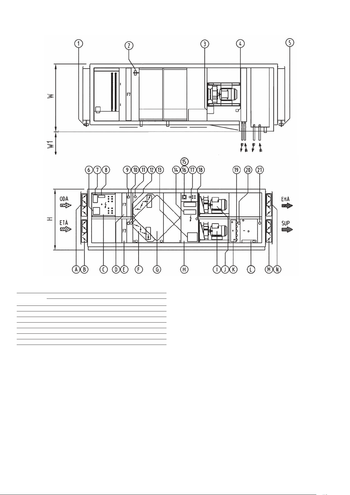
2.8 - Schematic diagram of an air handling unit ............................................................................................................... 6
3 - CHECKLIST OF START-UP CHECK POINTS .......................................................................................................... 9
3.1 - Checklist of start-up check points .......................................................................................................................... .9
4 - START-UP INSTRUCTIONS ................................................................................................................................... 10
4.1 - Casing ................................................................................................................................................................. .10
4.2 - Dampers .............................................................................................................................................................. .12
4.3 - Air filters ............................................................................................................................................................... .13
4.4 - Heaters ................................................................................................................................................................ .13
4.5 - Coolers ................................................................................................................................................................ .14
4.6 - DX Coils ............................................................................................................................................................... .15
4.7 - Heat recovery wheel ............................................................................................................................................. .15
4.8 - Plate heat exchanger ............................................................................................................................................ .16
4.9 - Recirculation damper ........................................................................................................................................... .16
4.10 - Fan .................................................................................................................................................................... .16
4.11 - Silencers ........................................................................................................................................................... .19
4.12 - Lighting .............................................................................................................................................................. .19
4.13 - Control panel ..................................................................................................................................................... .20
4.14 - Installation of external sensors included ............................................................................................................. .21
4.15 - Sensor Replecament ......................................................................................................................................... .22
5 - MAINTENANCE CHECKLIST ................................................................................................................................. 23
5.1 - Checklist of check points and maintenance intervals ............................................................................................ .23
6 - MAINTENANCE AND OPERATING INSTRUCTIONS ............................................................................................ 23
6.1 - General ................................................................................................................................................................ .24
6.2 - Casing panels ...................................................................................................................................................... .24
6.3 - Doors and access covers ..................................................................................................................................... .24
6.4 - Flexible connections ............................................................................................................................................. .24
6.5 - Earthing ............................................................................................................................................................... .24
6.6 - Dampers .............................................................................................................................................................. .24
6.7 - Outside air intake ................................................................................................................................................. .24
6.8 - Filters ................................................................................................................................................................... .24
6.9 - Heaters ................................................................................................................................................................ .24
6.10 - Coolers .............................................................................................................................................................. .25
6.11 - Heat recovery wheel ........................................................................................................................................... .25
6.12 - Plate heat exchanger .......................................................................................................................................... .26
6.13 - Recirculation damper ......................................................................................................................................... .26
6.14 - Fan .................................................................................................................................................................... .26
6.15 - Silencers ............................................................................................................................................................ .27
6.16 - Control ............................................................................................................................................................... .27
7 - OPEN AND CLOSED INSTRUCTIONS .................................................................................................................. 28
Abbreviations
AHU - Air handling unit
PED - Pressure Equipment Directive
SUP - Supply air
ETA - Extract air
BMS - Building management system
HMI - Human machine interface
ODA - Outdoor air
EHA - Exhaust air
rh - Relative humidity
6
7

3
1 - SAFETY CONSIDERATIONS
1.1 - General
Air Handling unit (AHU) is a device used to regulate and
circulate air as part of a heating, ventilating, and air-
conditioning (HVAC) system. So it can not be used for
differents purposes. The 39SQ air handling units (AHUs)
has been designed and manufactured in accordance with
the CE machine directive. In order to guarantee safe
operation and use of the unit, please carefully read and
observe the instructions in this document and pay special
attention to the warnings that apply to this unit. Any
modifications in the design and/or installation of the AHU
that are carried out without discussion with Carrier and
without advance written agreement will result in the loss of
the right to any warranty claims and any claim for injury to
personnel as a result of these modifications.
All work must be carried out by sufficiently trained
personnel.
All applicable personal safety devices must be used to
ensure safe working conditions. Safety gloves, glasses and
shoes must be worn for all maintenance operations. A
respiratory protection mask must be worn when changing
the filters. This pictogram shows the safety requirements
for all maintenance operations.
The technical staff should be use the most suitable
lightining for maintenence and startup. The unit should be
lighted according to EN12100.
The A weighted equivalent continuous
sound pressure level is between 70 and
85 dB(A), depending on the motor size,
fan size and fan speed. This means that
ear defenders must be worn, when the
fan is running.
All doors and hatches must have at
least one lock that can only be opened
with a special device.
Heating and cooling coils are
manufactured and supplied in
accordance with guidelines of the
Pressure Equipment Directive (PED).
Do not walk on the roof panels of units
installed inside or
outside.
Technical staff who is responsible for startup and
maintanence, has to take occupational health and safety
trainings according to the relevant national laws and
obligations. Only technical staff who fits this definition is
allowed to work on (electrical) components. All power
supplies to the unit must be disconnected, before any work
can be carried out.
Switch off the supply voltage using the main disconnect
switch /emergency stop switch.
CAUTION: Electric heaters have a separate supply and
must be switched off separately.
Use of electical equipment with a voltage above 48 V is
only permitted if an earth leakage switch is installed that
complies with local and national regulations.
1.2 - Applications
The AHU is designed for the movement and conditioning of
air, unless otherwise agreed during the design stage.
Lifting point
This pictogram shows where the AHU must be lifted and is
positioned on the support beam.
Lifting prohibited
This pictogram shows that no horizontal transport devices
must be placed under this frame section, such as pallet
lifters or the forks of fork lift trucks. It is also forbidden to
place lifting devices for transport and storage under this
frame element.
1.3 - Instruction types
The following warning pictograms and labels with text are
used.
Earthing
This pictogram indicates where the AHU can be earthed
and is on one of the support beams beneath the casing in
the fan section. If a unit consists of several sections, only
one section needs to be earthed, provided the sections are
connected in the correct way.
• The electrical components in the AHU must be
earthed, except for components with double insulation
and/or components with a supply voltage below 50 V.
• The electrical components must be installed in
accordance with national and local regulations.

4
Central data
This label contains the data for the AHU, such as order
number, position number etc. If present, the label is
normally located on the access cover or the door of the fan
assembly.
If the AHU consists of several parts, each part must
have a label with the required data.
Hot surfaces
This pictogram indicates that there are components behind
this access cover, door or panel that can cause serious
burns when touched.
The surfaces that may be hot are the heater surfaces. If
there are special special customer-specific components
behind doors, access covers or panels that have hot
surfaces and pose a potential risk, this is also indicated by
this pictogram.
Electrical voltage
This pictogram indicates that there are electrical
components behind this access cover, door or panel that
may be dangerous for the user/installer. Only qualified
electrician is permitted to carry out work on these
components. Do not work on electrical components including
control panels, switches, VFD untill you are sure ALL POWER
IS OFF and no residual voltage can leak from capacitors or
solid state components. Lock open and tag electrical circuits
during servicing ( see annex1 for lock out tag out instructions).
If the operation is interrupted, confirm that all circuits are
deenergized before the operation is resumed. For this work
the regulations of the applicable international (a.o. IEC
61557, EN 50110 and ES 59009) and national (e.g. BS
7671) standards must be observed. The pictogram is
attached to the access cover for the electric heater control
box.
Rotating parts
This pictogram indicates that there are rotating parts
behind this access cover, door or panel which may cause
injury. The components that include rotating parts are the
fan and heat recovery wheel. If there are special customer-
specific components behind doors, access covers or panels
that include rotating parts and pose a potential risk, this is
also indicated by this pictogram.

5
Opening the fan door
This pictogram is positioned on the outside of the door or access cover of the fan assembly. This pictogram warns that the
fan must have been switched off and deenergised for a minimum of two minutes before the door or access cover is
opened. This pictogram also indicates that transport brackets must be removed before the fan is started up. This warning
also important for safety. Because of the positive pressure, fan doors can hit the technical personnel who opens the doors.
Other warning labels
CAUTION: All doors and access covers must be closed
before starting up the AHU.
Lifting and transport
An instruction is attached to the AHU that describes the
procedures that must be followed for lifting and transport.
The following chapter contains further details.
1.4 - Disposal of parts/materials
• The packaging material must be disposed of in a
responsible manner and in accordance with local
regulations.
• Components that are replaced, must be disposed of
as described above.
2 - TRANSPORT AND LIFTING INSTRUCTIONS
2.1 - General
Transport and lifting of the AHU must always be in
accordance with the instructions below. If these
instructions are not observed, the unit may be irreparably
damaged, and people in the immediate vicinity of the unit
are endangered. Carrier does not accept any responsibility
if these instructions are not observed. Transport and lifting
must be carried out by qualified personnel. The AHU must
only be lifted with lifting bars supplied by Carrier (box profile
30 x 30 x 4 mm). Lifting must be carried out in accordance
with local regulations and with the help of certified lifting
aids.
Only one set of lifting bars is supplied per order/position
number per unit width (if ordered). These lifting bars are
suitable for single use and only for the parts of this order/
position number. The lifting bars are certified by an
authorised person using a type test.
2.3 - Offloading and hoisting
Depending on the dimensions of the AHU and the situation
on site, the AHUs are supplied in previously agreed
transport sections.
Before proceeding with the transport and installation of the
casing sections, always consult the applicable dimensional
drawing that give the dimensions and weights of the
sections, as well as the installation sequence.
The weight is given on each transport section. Each
transport section is equipped with a subframe with four
lifting points. These points are marked by the label shown
below.
2.2 - Transport and storage
During transport and storage the air handling unit must only
be supported under the designated lifting points.
Supporting and lifting under the cross beams is prohibited.

6
2.4 - Horizontal transport
For horizontal movement pallet lifters or transport skids can
be placed under the installation frame or under the lifting
bars. It is important that these support the lifting points. At
no time should the cross beams at the ends of the unit
sections be used for jacking or tracking the AHU. FOR
HORIZONTAL TRANSPORT ALWAYS PROVIDE SUPPORT
UNDER THE LIFTING POINTS. The use of bars as rollers
can result in damage to the installation frame.
For offloading as well as hoisting lifting cables can be
attached to the lifting bars. Evenly positioned spacer bars
should be used between the lifting cables to prevent
damage to the top of the unit and ensure that no excess
pressure is applied to the side panels. For hoisting please
ensure that the weight is evenly distributed. And please use
CE marked hooks.
The AHU should not be lifted or moved under the cross
beams.
2.5 - Storage
The packaging in which the AHU is supplied can cause
condensation to be formed between the packaging and
the AHU, if the unit is stored in an unconditioned place.
Storage temperature will be between –25 to 55 oC
according to EN 60204-1. If the AHU is not immediately
used it is recommended to store it in a conditioned location
on-site. If the AHU is kept outside for a short period direct
sun radiation must be avoided.
If the fans are shut down for a longer period (longer than
three months) bearing damage can occur. To prevent this it
is recommended to loosen the belt tension or to
temporarily remove the fan belts. When the fans are
re-started the belt tension must be reset to the specified
tension. Controlled rotation of the fan impeller can also
prevent this type of damage. This is also recommended for
direct-drive fans.
2.6 - Warranty
The units will 2 years warranty after invoice date if startup,
storage and maintenance are made according to this
manuel.
2.7 - Placement
The unit have to be placed on a dry floor surface which can
handle the weight and do not give permission to slide or
vibrate. Anti vibration pads can be used if needed.
2.8 - Schematic diagram of an air handling unit
The two versions of the 39SQ with heat recovery shown
here in schematic diagrams with a short description.
The drawings in this document are for information only and
show the various versions. They do not include possible
external sensors or control devices. The air flow direction
shown is from LEFT to RIGHT.
The dimensions given in the drawings (H and W) refer to
the outside dimensions of the
AHU casing (excl.
connections and additional components).
Dimension
W1min is the required service clearance in front of the
AHU. W1rec is the recommended service clearance in front
of the AHU to replace components.
For horizontal movement pallet lifters or transport skids can
2.7 - Placement
The unit have to be placed on a dry floor surface which can
handle the weight and do not give permission to slide or
vibrate. Anti vibration pads can be used if needed.
2.8 - Schematic diagram of an air handling unit
The two versions of the 39SQ with heat recovery shown
here in schematic diagrams with a short description.
The drawings in this document are for information only and
show the various versions. They do not include possible
external sensors or control devices. The air flow direction
shown is from LEFT to RIGHT.
The dimensions given in the drawings (H and W) refer to
the outside dimensions of the
AHU casing (excl.
connections and additional components).
Dimension
W1min is the required service clearance in front of the
AHU. W1rec is the recommended service clearance in front
of the AHU to replace components.
2.6
2.7

7
39SQR with high-efficiency heat recovery wheel
Sizes 0606, 0707, 0808, 0909, 1010, 1111, 1212, 1412 and 1416
Dimensions
39SQR Dimensions in mm
H W W1min W1rec
0606 1120 1148 700 1190
0707 1280 1308 700 1350
0808 1440 1483 700 1525
0909 1600 1643 700 1685
1010 1760 1803 700 1845
1111 1920 1963 700 2005
1212 2080 2138 700 2180
1412 2080 2458 700 2500
1416 2720 2458 700 2500
W1 min= minimum service distance
W1 rec= recommended service distance,
Recommended service distance on top of the unit is 1.5 meter.
If the customer doesn’t leave sufficient service distance,
Alarko Carrier does not accept any responsibility about commissioning
or service problems.
Legend
A. Exhaust air damper
B. Outdoor air intake damper
C. Electric pre-heater (hot water)
D. Supply air filter
E. Extract air fan
F. Control panel
G. Motor, heat recovery wheel
H. Heat recovery wheel
I. Recirculation damper
J. Supply air fan
K. Extract air filter
L. Electric reheater (hot water)
M. Cooling coil with changeover
N. Supply air damper
O. Extract air damper
Legend
1. Actuator, outdoor air damper
2. Pressure sensor, extract air fan
3. Frequency converter, extract air fan
4. Actuator, recirculation air damper
5. Frequency converter, supply air fan
6. Pressure sensor, supply air fan
7. Actuator, extract and supply air damper (2 x)
8. Main disconnect switch (supply), electric heater
9. Electrical heater switching components
10. Fuses, electric heate
11. Pressure switch, supply air filter
12. Controller, heat recovery wheel
13. Main supply connection, control panel
14. Main disconnect switch / emergency stop switch
(excl. electric heater)
15. Connection terminals
16. Pro-Dialog control
17. Reset button
18. Temperature sensor, air intake
19. Temperature sensor, extract air
20. Pressure switch, extract air filter
21. Relay
22. Frost protection thermostat, heating coil
23. Temperature sensor, DX coil inlet
24. Temperature sensor, supply air

8
39SQP with cross-flow plate heat exchanger
Sizes 0405, 0506, 0606, 0707, 0808, 0909 and 1010
Dimensions
39SQP Dimensions in mm
H W W1min W1rec
0405 960 813 600 855
0506 1120 973 700 1015
0606 1120 1148 700 1190
0707 1280 1308 700 1350
0808 1440 1483 700 1525
0909 1600 1643 700 1685
1010 1760 1803 700 1845
W1 min= minimum service distance
W1 rec= recommended service distance,
Recommended service distance on top of the unit is 1.5 meter.
If the customer doesn’t leave sufficient service distance,
Alarko Carrier does not accept any responsibility about commissioning
or service problems.
Legend
A. Outdoor air intake damper
B. Extract air damper
C. Electric pre-heater (hot water)
D. Supply air filter
E. Extract air filter
F. Recirculation damper, plate heat exchanger
G. Plate heat exchanger, incl. face/bypass damper
H. Control panel
I. Supply air fan
J. Extract air fan
K. Electric reheater (hot water)
L. Cooling coil with changeover
M. Supply air damper
N. Exhaust air damper
Legend
1. Actuator, outdoor air, extract air damper (2 x)
2. Actuator, face/bypass and/or recirculation air damper, plate heat
exchanger
3. Frequency converter, extract/supply air fan (2 x)
4. Pressure sensor supply/extract/supply air fan (2 x)
5. Actuator, supply/exhaust air damper (2 x)
6. Main disconnect switch (supply), electric heater
7. Electrical heater switching components
8. Fuses, electric heater
9. Pressure switch, supply air filter
10. Pressure switch, extract air filter
11. Temperature sensor, air intake
12. Temperature sensor, extract air
13. Relay
14. Pro-Dialog control
15. Main supply connection, control panel
16. Main disconnect switch, / emergency stop switch
AHU (excl. electric heater)
17. Connection terminals
18. Reset button
19. Frost protection thermostat, heating coil
20. Temperature sensor, DX coil inlet
21. Temperature sensor, supply air

9
3 - CHECKLIST OF START-UP CHECK POINTS
3.1 - Checklist of start-up check points
Before commissioning the unit, all functions below and the associated components must be checked, using the check list below.
The table below shows a general overview of the planning required to facilitate the installation of the AHU. The following pages give
a more detailed description of the individual components. The unit should be lighted according to EN12100 during maintenance
operation.
CAUTION: “Technical staff who is responsible from startup and maintenence, has to take occupational health and safety
trainings according to the relevant national laws and obligations.” Do not work on electrical components including control
panels, switches, VFD untill you are sure ALL POWER IS OFF and no resudual voltage can leak from capasitors or solid state
components. Lock open and tag electrical circuits during servicing. If work is interrupted, confirm that all circuits are deenegized
before resuming work. Before starting up the AHU ensure that the components have the correct connection voltage and
connect them in accordance with the regulations. The doors and access covers must be closed and the AHU must be earthed
.
Start-up check points
Function Components Check points Start-up
General All functions Remove obstacles and loose debris from compartment
All functions Check for possible condensate and if necessary dry the parts
indoor installation/
outdoor installation
Internal and external panels Damage
Joints Cracks
Doors/access covers Must be closed and locked before start-up
Flexible connections Correct installation
Earthing Correct earthing in accordance with regulations
Roof covering (outdoor installation) Check if roof is completely watertight
dampers Correct operation
Blades fully closed and at zero position
Actuators Correct operation
Check rotation direction
Actuator end position same as damper end position
Filters Correct filter type
Are the filters correctly installed
Pressure differential gauge Correct operation
Pressure differential switch Correct operation/set-up
Heaters Hot-water coil Correct connections
Air vent the coil
Leakage
Frost protection thermostat connected
Electric heater Check heater earth
Check hatch earth
Correct fuse size
Check wiring diagram
Check for possible condensate and if necessary dry the heater
Coolers Chilled-water coil Correct connections
Air vent the coil
Leakage
Droplet eliminator Correct alignment
Drain trap Correct connection
Heat recovery wheel Rotor Check rotation direction
Seal Correct seal towards wheel
Drive Check connection voltage
Correct connection
Check current in all phases
Drive belt Check tension
Rotation monitor Correct connection
Controller Correct connection
Plate heat exchanger Damper (if used) Correct operation
Actuator (if used) Correct operation
Fan Transport protection brackets Remove
Fan housing and fan compartment Remove obstacles and loose debris from the fan and fan compartment
Fan compartment, fan, motor, frequency converter Check for possible condensate and if necessary dry the parts
Impeller Check rotation direction
Motor Check connection voltage
Correct connection
Check current in all phases
Drive belt Check tension
Flexible connections Correct installation
Operating switch Check connection
Ensure switch is locked off during checks
Frequency converter Connections Correct connection/complies with EMC
Frequency converter Check for possible condensate and if necessary dry the converter
Voltage Check connection voltage
Settings Check correct settings
Phases Check voltage in all phases
Lighting Lamp Check connection voltage
Control panel Components Check for possible condensate and if necessary dry the components
Power supply Check power supply voltage
Check neutral
Correct earthing in accordance with regulations
Power supply with correctly sized fuses
External sensors/control devices Connect according to wiring diagram
Alarms Connect to BMS or external panel
Controller Parameters Set all specific project parameters

10
4 - START-UP INSTRUCTIONS
4.1 - Casing
The unit data, such as order number, position number etc.
is given on the nameplate.
Note: Making a hole or mounting different components
on panel while start up, can affect the air handling unit
mechanical classes
4.1.1 - Casing panels
Check the AHU panels for any damage. Any dirt or stains
must be removed from the surface to prevent possible
long-term damage. Dirt can be removed with water and a
mild house-hold soap solution. Damage can be repaired by
throughly cleaning the affected surface, then treat and paint
as necessary. If applicable check the sealing joints and
repair if required.
4.1.2 - Doors and access covers
Check the operation of door handles, locks and movement
of the hinges. Check if the door closure (on the inside of the
door) is tightly fitted, so that there are no excessive air leaks
at the doors. For outside installation of the AHU check the
storm cord.
CAUTION: Doors and access covers must always be
closed before starting the unit.
4.1.3 - Flexible connections
• Check that all flexible connections are attached to the
AHU. If necessary, tighten loose screws.
• The stretched length of a single-skin flexible
connection is 170 mm, but a flexible connection must
NOT be installed stretched between the AHU and the
duct. Once installed the operating length of the flexible
connection must be 100 mm.
4.1.4 - Earthing
Ensure that the AHU has been earthed correctly and in
accordance with local regulations. A label on the support
frame indicates where the unit should be earthed.
4.1.5 - Connected ducts
• Inlet and outlet sections could be full face opening or
full face damper with flanges. For all fan types
(forward, backward or plug) duct have to be fixed
from flanges.
• It is recommended to use Europrofile connections
(type E30) at the corner frame as well as at the
duct to be connected.
• The Europrofile connections are available in fixed
lengths and can be cut to the required length with
a saw. These profiles can easily be placed over the
corner frame. Allow for a maximum profile height
of 30 mm, so that ducts that are positioned one
above the other can be installed correctly.
• The four corners between the profilles can be
completed with a corner piece (type H30).
• The profile at the corner frame can be attached to
the profile on the duct using a drive slip (type SR).
• Attaching self-adhesive tape between the two profiles
ensures an air-tight seal, as shown in the drawing
below.
8.5 mm
27 mm
27 mm
15 mm
105 mm
ø 11 mm
30 mm

11
• To be able to make two openings one above the other
the corner frames of the two openings have a different
length so that there is always enough space to place
and attach the profiles. Using the drive slip means that
there is no need to use screws in the limited space
between the two ducts that are one above the other,
as shown in the drawing below.
• The corner frame has a length of 32 or 72 mm and
extends 22 or 62 mm beyond the external AHU
dimension, as shown in the drawing below.
• The flexible connection, including the installed corner
frame, extend 170 mm beyond the external AHU
dimension, and a damper set 132/172 or 207/247
mm, as shown in the drawing below.
Legend
1. AHU
2. Flexible connection or damper
3. Duct connection
(single-skin flexible connection - ± 30 mm press fit)
• The combination of flexible connections and dampers,
including the installed corner frame, extends 302/337
or 342/417 mm beyond the external AHU dimension,
as shown in the drawing below.
If these can be expected for the installation or geographical
location, try to minimise them with partitions. If there is any
possibility that rain water can be drawn in, droplet
eliminators must be added behind the air intake grille. A
pre-heater for the filters can be installed to prevent that
mist causes the filters to become too wet. The pre-heater
will reduce the relative humidity of the air.
Connection of the outdoor air intake duct
If condensation can be expected in or on the ducts, these
must be insulated on the outside.
To connect the outdoor air intake duct to a unit that is
installed inside we recommend the following procedure:
• Connect a 500 mm long adapter piece to the corner
frame of the air handling unit.
• Insulate the inside of the complete adapter piece up to
the unit panel.
• Insulate the outside of the adapter piece so that there
is a 250 mm overlap between inside and outside
insulation.
• The remainder of the adapter piece needs to be
insu-lated on the outside, as shown in the drawing
below.
4.1.6 - Outdoor air intake
• Ensure that the air intake duct is correctly connected.
High air velocities must be avoided and no rain drops
should get into the duct. This can be prevented by
installing rain protec-tion air intake grilles (Caution: The
maximum air velocity for the grille is as given by the
supplier). The rear air intake duct must be sized to
avoid higher than allowable air veloci-ties in the grille.
High air velocities in the openings can also be caused
by wind attacks at one of the openings.
(single-skin flexible connection - ± 30 mm press fit)
Legend
1. AHU
2. Duct connection
Legend
1. AHU
2. Damper
3. Flexible connection
4. Duct connection
302/337 or 342/417 mm
170 mm 132/172 or 207/247 mm
22/62 mm

12
4.2 - Dampers
• Check if the actuator motor is installed in accordance
with the supplier’s instructions.
• Check if the correct angle has been set.
• Check if the dampers close properly.
• Check if the damper can open to the required angle.
• Check operation after the power has been restored
following a power cut. Some dampers must be open,
others must be closed.
If a damper is installed on the unit it is recommended to
insulate up to the unit (over the damper). The damper can
cause condensation to form on the unit.
4.1.7 - Assembly and placement of the air handling unit
Ensure that the floor in the room where the unit is installed
is even and waterproof. The joints between the parts must
be covered with the sealing tape provided. The sections
can then be placed in the correct order. Place the sections
as close as possible together and ensure that they can be
moved. Using a support, pull the sections towards each
other with a pull-rope. Check if all parts are water-tight and
if necessary slide spacers under the support where
required (see also chapter 2). Then attach the profiles
supplied to the joint. The roof of units installed outside
must be sealed so that no water can leak to the inside.
Always attach a unit installed outside to the floor of the
support frame, to ensure that the unit cannot move or fall.
(take the force of the wind into account). For units installed
inside please make sure that the unit cannot move from its
support points. If necessary, the unit must be attached to
the support.
4.1.8 - Air contamination
If the exhaust and outdoor air intake openings are close to
each other there is a risk of air contamination. To reduce
contamination the air must be rarefied. To do this correctly,
the air volume, the horizontal and vertical distance to the
two openings and the position of the two openings in
relation to each other must be taken into consideration (is
the outdoor air intake lower or higher than the exhaust air
opening).
It may be necessary to position the two openings further
apart, using an extra piece of duct at the outdoor air intake
opening. If the units are installed outside, this piece of duct
should be placed between the air handling unit and the
pre-installed suction cap (if used). The piece of ducting
must always be supported in an appropriate way.
4.1.9 - Condensation in or on the AHU
Condensation can form on the inside and outside the AHU.
This depends on the installation location (indoor or
outdoor), temperature and relative humidity inside and
outside the AHU and the thermal bridge factor (theTB
value) of the AHU. Always select an AHU with a thermal
bridge factor that will not lead to condensation at the
indoor and outdoor conditions. For units installed inside the
following points must be considered:
• Open water collection tanks (e.g. vapour/condensate
collection tank). These must always be unpressurised
and covered so that the relative humidity in the plant
room is minimised.
• Sufficiently insulate the cold water and condensate
lines up to the AHU.
• Sufficiently insulate air ducts with a possible air
temperature below the dew point of the air in the plant
room, as described earlier.
For units that are installed outside the following points must
be considered:
• Always insulate air ducts with a possible air condition
(temperature and relative humidity) with a dew point
above the expected outdoor air condition, to prevent
condensate formation in the duct. It is recommended
to insulate all ducts from and to the building to
minimise heat transfer and to ensure good control
• After connecting the ducts to the building immediately
connect the unit to the power supply, switch it on and
start it up. If this is not done moisture will move from
the building ducts to the AHU, causing an increase of
the relative humidity in the AHU. At low outdoor
temperatures (if the AHU is not operating) this can lead
to condensation in the AHU and the control panel.
This must always be prevented.
4.1.10 - AHU support
The AHU incorporates a 62-mm high self-supporting base.
If the AHU is placed on a base or an external frame, the
following dimensions of the support under the AHU must
be taken into consideration
Unit length:
AHU width
Unit width: (Dimensions in mm)

13
Manual operation Actuator-assisted operation
4.3 - Air filters
• Check if the correct filters have been installed.
• Check if the filters have been installed correctly.
• Set pressure switches or filter indicators, if used.
• Close the inspection door.
For manual operation the damper blades can open via
hexagon-socket-screw key which is mounted on the
actuators.
AHU with control
The unit is supplied as standard with actuator(s).
• Open/closed
• Spring return
AHU with control
The supply and extract air filters are equipped with a
pressure switch that is configured in series and normally
closed.
AHU with control
The first hot water coil without glycol in air flow direction is
equipped with a frost protection thermostat. This is set to a
cut-out temperature of 5oC.
4.4.1.1 - Coils containing glycol
If coils are filled with a water/glycol mixture, this requires
extra attention.
• Glycol can react violently with strong oxidation
solutions.
• When working on the coil, always check which
medium is used. Before adding anything to the heat
exchange medium, always check with the installer.
• Always wear safety glasses, gloves and shoes.
• Do not smoke or use an open flame.
• When sizing the expansion tank take the higher heat
transfer coefficient into account, (± 25% larger).
• Watertight seals are not always tight for water/glycol
mixtures. It is therefore better to use weld/solder
connections.
• Water/glycol causes increased sludge formation.
• Always observe the instructions of the right glycol
manufacturer.
• Check the mixture to ensure that the glycol concen-
tration (by weight) is correct.
4.4.2 - Electric heater
• Check and/or connect the heater in accordance with
local regulations and the data from the manufacturer.
• Ensure that the terminal strip earth and the inspection
hatch earth have been connected.
• Check for possible condensate/moisture. Condensate
may form in the period before the first start-up of the
AHU as a result of weather change and/or humid air
from the building. Remove all condensate from the
construction components and dry the electrical
components using warm (dry) air (e.g. with a hair
drier).
• Check the connection voltage.
• Check the existing amperage on all phases. The
values must agree with the data on the heater name
plate.
• To ensure safe operation of the heater, it is equipped
with a thermostat with auto reset (70 °C) and and a
high limit thermostat with manual reset (110 °C).
ATTENTION:
• Do not enter the AHU if the electric heater is on.
• The instructions must clearly specify that the fan
must be operating, before the electric heater is
switched on. After the heater has been switched
off, the fan must continue to run for at least five
minutes.
• As not all electric heater stages have variable
control, always ensure that the minimum speed
across the heater is 2 m/s. If all stages have
variable control the air velocity over the element
can go down to 1.5 m/s.
• The warning label for electrical voltage is attached to
the inspection hatch.
• Ensure that the end position of the damper is the
same as the end position of the actuator so that the
drive lever of the damper is unloaded in the end
position.
4.4 - Heaters
4.4.1 - Hot water coil
• Check the connections on the dimensional drawing.
• Ensure that the coil has been fully purged.
• Check connections for leakage.
• Ensure that the frost protection thermostat has been
correctly connected and set up.
• It is possible that the coil is the last or second last
component in the AHU. The frost protection
thermostat must be made accessible by providing a
field-installed inspection hatch in the supply air duct
• Ensure that the heater can supply heat to prevent frost
formation when the fan is started.
• City water can be used for water coils without any
conditioning.
CAUTION: When the coils are drained, no water must
remain in the circuits to prevent freezing at
temperatures below zero.

14
• The earth warning label is attached to the inside of the
heater and the inspection hatch.
The product complies with residential EMC standards EN
61000-4-2, EN 61000-4-3, EN 61000-3-2, EN 61000-3-3,
EN 61000-3-11, EN 61000-3-12, EN 61000-6-2, EN
61000-6-4, EN 55016-2-1, EN 55016-2-3, EN 55014-1
with the following restrictions, related to the flicker effect.
Only one heater
Heating
capacity
Current/
phase
Maximum
Impedance Z
Declaration of the connection condition
to comply with
7.5 kW 11 A 0.309 Minimum power supply capability at the
building connection point to the public
network > 100 A per phase
9 kW 13 A 0.257
11 kW 16 A 0.210
15 kW 22 A 0,154 Maximum allowable power supply
network impedance < 0.15 Ohm
18 kW 26 A 0.128 Maximum allowable power supply
network impedance < 0.13 Ohm
19 kW 27 A 0.122 Maximum allowable power supply
network impedance < 0.12 Ohm
24 kW 35 A 0.096 Maximum allowable power supply
network impedance < 0.10 Ohm
27 kW 39 A 0.086 Maximum allowable power supply
network impedance < 0.09 Ohm
35 kW 51 A 0.066 Maximum allowable power supply
network impedance < 0.07 Ohm
40 kW 58 A 0.058 Maximum allowable power supply
network impedance < 0.06 Ohm
* Maximum value at the point of common coupling (PCC) of the machine and
other electrical devices sensitive to the flicer effect
The values in the table above are calculated based on the
following assumptions
• Power supply 400 V
• Safety margin 10%
• A voltage change as defined by the standard
corresponds to a cycle ON – OFF – ON
• For an interval period of 50 seconds
4.5 - Coolers
• Check the connections in accordance with the
dimensional drawing.
• Ensure that the coil has been fully purged.
• Control the connections for leaks.
• If a changeover coil is supplied by a heat pump, the
installation must be designed to compensate for the
required heat during the system heat pump defrost
cycle and the heat cannot be drawn from the supply
air. Otherwise the supply air temperature cannot be
achieved. During the heat pump defrost cycle it must
be possible to add so much heat into the system that
the desired entering temperature (heater design
capacity) as well as the required heat for heat pump
defrosting can be guaranteed.
• Ensure that the AHU is installed high enough to enable
the siphon trap to work correctly.
• Check that the siphon trap (option) has been correctly
installed.
• Check if siphon cover and ball have been correctly
installed.
AHU with control
Do not work on electrical components including control
panels, switches, VFD untill you are sure ALL POWER IS
OFF and no resudual voltage can leak from capasitors or
solid state components. Lock open and tag electrical
circuits during servicing. If work is interrupted, confirm that
all circuits are deenegized before resuming work. If an AHU
with control includes an electric heater, this must have a
separate power supply (400 V ± 10%, 3 phase, 50Hz +-%2)
the electric heater supply must be protected by a correctly
sized fuse. The control ensures the correct control signal
and the minimum air flow across the heater.
The electric heater includes:
• A main disconnect switch
• Internal fuses (fast acting)
• Circuit control devices and switching elements that
ensure modulating control.
4.4.3 - Electric heater in combination with changeover
coil
For an AHU with control an electric heater combined with a
changeover coil can be used. The changeover coil provides
primary heating and cooling. The electric heater is used as
a back-up heater in case there is no hot water available for
the changeover coil at a demand for heating. The electric
heater must NOT be used if the changeover coil is
operating and the required entering temperature is not
achieved.

15
Positive pressure:
H1 = >maximum positive pressure in the cooler section (in mm WG) + 50 mm
H2 = 50 mm
Pressure in kPa (100 Pa = 10 mm WG)
• Check if the droplet eliminator after the cooler has
been correctly installed.
• Check if fins have been bent during transport.
• Correctly straighten the fins.
• The fins will only work correctly after several days in
dehumidification mode.
• Start-up the cooling coil by opening the shut-off
valves. After several days of cooling operation check
the condensate drain and operation of the plastic
siphon.
• If necessary clean the siphon.
• City water can be used for water coils without any
conditioning.
4.7 - Heat recovery wheel
• Ensure that the heat exchanger face area is not
damaged.
• Check that the wheel is rotating in the correct
direction.This is indicated by an arrow on the casing.
• Check if the wheel seals are fitting correctly.
• Check if belt tension is correct.
• Check if the motor and the rotation monitor have been
correctly connected (5 mm play between sensor and
detection point on the wheel).
• Ensure that the rotor speed has been correctly set.
The 39SQ condensation rotor must have a maximum
speed of 10 min-1; a sorption rotor must have a
maximum speed of 20 min-1. Refer to the user manual
for the heat recovery wheel controller.
• If the air intake temperature is below -15 °C, a pre-
heater is recommended for the heat recovery wheel to
prevent freezing.
4.6 - DX-coils
• The DX-coils are supplied without refrigerant.
• The coils must never be pressurised with water. They
must be sealed and pressurised with a gaseous
medium to prevent pollution of the coil.
• A qualified person should charge the coil and the rest
of the system with a sufficient amount of the refrigerant
specified in the technical specifications.
• When connecting the DX-coil to the compressor/
condensing unit always follow the supplier
specifications and the instructions of the qualified
personnel.
• It is not recommended to connect several DX-coils to
one compressor/condensing unit.
• It is best to use an infinitely variable controller for the
compressor / condensing unit. If the condensing unit
has infinitely variable control, one of the temperature
controls in the controller can be selected.
• If the condensing unit does not have infinitely variable
control, set the AHU control for supply air temperature
control, and connect the DX entering temperature
sensor instead of the supply air sensor. The desired
(room) temperature must then be controlled by a
separate controller at the condensing unit.
If a changeover coil is supplied by a heat pump, the
installation must be designed to compensate for the
required heat during the system heat pump defrost cycle
and the heat cannot be drawn from the supply air.
Otherwise the supply air temperature cannot be achieved.
During the heat pump defrost cycle it must be possible to
add so much heat into the system that the desired entering
temperature (heater design capacity) as well as the
required heat for heat pump defrosting can be guaranteed.
AHU with control
To ensure that the correct control strategy for an AHU with
DX-coil can be selected, there is a temperature sensor on
the intake side of the DX-coil. If a heater is placed directly
before the DX-coil, this sensor is only accessible, if an
inspection section is installed between the two coils.
WARNING:
AVOID SPILLING liquid refrigerant on skin or getting it into
the eyes.
USE SAFETY GOGGLES. Wash any spills from the skin
with soap and water. If liquid refrigerant enters the eyes,
IMMEDIATELY FLUSH EYES with water and consult a
physician.
Fill siphon with water, if the fan is switched off.
Negative pressure:
H1 = maximum negative pressure in the cooler section (in mm WG) + 50 mm
H2 = >1/2 x H1
• Check that the (negative or positive) pressure
corresponds to the siphon type installed.
• The outlet of the siphon trap connected to the drain
must not be under pressure.
• It is not recommended to connect a siphon in a
negative pressure section and a siphon in a positive
pressure section via a manifold that is not under
pressure to the drain. Instead two separate manifolds
should be used.
• If the field-prepared siphon is used, follow the
instructions in the drawing below.

16
4.8 - Plate heat exchanger
• Ensure that the face area of the heat exchanger is not
damaged.
• If dampers are installed, also check if the actuator
motor has been installed in accordance with the
instructions of the supplier.
• Check if the correct angle has been set.
• Check if the dampers close correctly.
• Check if the dampers can reach the fully open
position.
• If the air intake temperature at the is below -10 °C in a
cross-flow plate heat exchanger, a pre-heater is
recommended for the plate heat exchanger to prevent
freezing.
AHU with control
The plate heat exchanger is supplied with a modulating
actuator (24 V).
4.10 - Fan
Remove before
transport
The following warning sign is shown on the panel.
Rotating parts
If required the heat recovery wheel can include a pressure
sensor that protects the rotor against freezing.
AHU with control
The heat recovery wheel is supplied with rotor control,
included in the central control panel. The rotation monitor
for the rotor is pre-installed and connected.If required the
heat recovery wheel can include a pressure sensor that
protects the rotor against freezing.
AHU with control
The recirculation damper is supplied with an open/closed
actuator with spring return (24 V). The control used for the
recirculation damper is an open/closed control
4.9 - Recirculation damper
• Before operating this damper refer to chapter 4.2
• The damper must always be closed at a power failure
or when the unit is shut down.
• If a recirculation damper is used a damper must be
included for both the outdoor entering and exhaust air
opening.
• The recirculation damper used is designed for an
open/closed application.
• The AHU with recirculation damper is therefore NOT
suitable for modulating operation of the recirculation
damper. This is due to the non-guaranteed damper
authority and the fan position in the AHU relative to the
recirculation damper.
start-up

17
CAUTION: The air flow may cause stationary parts to
move (even a fan that is switched off).
• Remove the transport brackets. This is indicated by a
label on the door.
• Check if the fan can move freely without obstructing
the frame, flexible connection or wiring.
• Check for possible condensate/moisture. Condensate
may form in the period before the first start-up of the
AHU as a result of weather change and/or humid air
from the building. Remove all condensate from the
construction components and dry the electrical
components using warm (dry) air (e.g. with a hair
drier).This applies to both motor and frequency
converter.
• Check the connection voltage.
• Check and/or connect the motor in accordance with
local instructions and the data of the supplier.
• Check the direction of rotation of the impeller. The
direction is indicated on the fan by an arrow.
• Separately measure the current draw of the electric
motor for all phases. The current draw of all phases
must be approximately the same and agree with the
data on the name plate. Set the motor protection
device to the nominal value.
• The motor data shown is for an altitude above sea
level of up to 1000 m and an ambient temperature of
40 °C maximum.
• The data for belt type, belt tension, number of belts,
size and type of pulley is given on a sticker on the fan
housing.
• If the fans are shut down for longer periods (longer
than three months), the bearings may be damaged. To
prevent this it is recommended, to reduce the fan belt
tension or to remove the fan belts temporarily. When
the fans are restarted the belt tension has to be reset
to the specified value. This type of damage can also
be prevented by controlled rotation of the fan impeller
This is recommended for direct-drive fans.
• Check if the flexible connection is correctly installed.
• If used check the pressure switch and set the correct
pressure.
• Check the operation of the main switch / emergency
stop switch.
CAUTION: While working on the fan the switch has to
be locked open.
• This warning also important for safety. Because of the
positive pressure, fan doors can hit the technical
personel who is opening the doors.
• Before openning the doors, the fan must be switched
off, isolated and allowed to rundown
(2 minutes minimum)
• The warning pictograms on rotating parts, electrical
voltage and opening doors are attached to the door.
General data, fan motor
Insulation class motor : F
PTC trip temperature : 155 °C
Connection voltage : 3 x 230V+-%10/50 Hz
3 x 400 V +-%10
The fan motor must have a power supply of 230V+-%10,
3 ph, 50Hz+-%2 or 400 V +-%10, 3 ph, 50Hz+-%2.
The connection must be made with short circuit protection
(fuses) and a thermal motor safety switch, matched to the
nominal current of the motor. The motor can also be
protected against overheating by three series-connected
PTC thermistor fuses, installed in the windings. If a
frequency converter is used the thermistors must be
connected to the converter.
Before connecting the power supply please check the
diagrams on the next page to ensure that they agree with
the data on the motor name plate and the data in the
technical documentation.
The disconnect switch is located on or near the fan
section. When working on the unit the switch must be
turned off and secured with a padlock. Switching off the
disconnect switch must be done when the unit is not
energised. If work is interrupted, confirm that all circuits
are deenegized before resuming work.
Risk of injury or death by electrocution. High voltage is
present on motor leads even though the motor is not
running when a VFD is used. Open the power supply
disconnect before touching motor leads or terminals
Before opening the door or inspection hatch of the fan
section (failure, maintenance, service) all power supply
circuits must be switched off.
CAUTION: Motors with a power output of up to 2.2 kW
(230V+-%10 / 400V +-%10) have across-the-line
starting. Motors with a power output of 3 kW (400
V+-%10) should be started with the star/ delta switch.
Thermal motor fuse
If the machine has stopped due to an unexpected power
supply failure, sudden re-starting of the machine must be
avoided. The control system must include an appropriate
protection device.

18
Connection diagrams: connection of the power supply cable and of the terminals on the terminal strip
4.10.1 - Plug fans
Plug fans are fans without a scroll that are directly driven by
the motor. To get the correct operating point for this type of
fan a frequency converter is required. The maximum
frequency at which the plug fan can rotate depends on the
motor/impeller assembly and should normally be higher
than 50 Hz. The maximum frequency is given on the fan
name plate.
Plug fans are equipped with a pressure measurement point
in the intake cone of the fan. By measuring the pressure
drop between the pressure for the fan and the pressure in
the intake cone the actual air flow can be calculated using
the following formula: V = k ·√∆pst
Where
V = actual air flow rate in m3/h
k = specific fan coefficient
∆pst = pressure differential cone/air intake section in Pa

19
The k-value depends on the fan size used. This value can
be found in the table below.
k-values
Fan size Plug fan
225 47
250 60
280 75
315 95
355 121
400 154
450 197
500 252
560 308
630 381
710 490
4.10.2 - Frequency converters
It is recommended to install a frequency converter with an
integrated operating switch. If a separate operating switch
is installed on the unit and near the frequency converter,
this can be located in the supply voltage for the frequency
converter. If the frequency converter is not installed near
the unit/operating switch, the operating switch can be
placed in the control power circuit, that switches the supply
voltage to the frequency converter via a relay. To connect
the frequency converter, please refer to the wiring diagram
for the converter installed. Ensure that the EMC directives
are observed and pay attention to the shielded cables.
The frequency converter must always be correcly set to
suit the motor and type installed. Observe the instructions
of the supplier of the frequency converter. Special attention
should be given to the following parameters:
• Correct application of the general motor data
- Pay special attention to the motor frequency.
- For subsynchronous operation (lower than the
network frequency) it must be set in accordance
with the motor nameplate.
- For supersynchronous operation (higher than the
network frequency) it must be set for the
maximum admissible frequency of the motor/
impeller assembly (this applies above all to plug
fans.)
• Operating type, square variable connection
• It is recommended to cut out so-called overmodulation
• Setting of the normal start-up/shut-down times.
• Check for possible condensate/moisture. Condensate
may form in the period before the first start-up of the
AHU as a result of weather change and/or humid air
from the building. Remove all condensate from the
construction components and dry the electrical
components using warm (dry) air (e.g. with a hair
drier).
• Do not work on electrical components including
control panels, switches, VFD untill you are sure ALL
POWER IS OFF and no resudual voltage can leak from
capacitors or solid state components. Lock open and
tag electrical circuits during servicing. If work is
interrupted, confirm that all circuits are deenergized
before resuming work. Risk of injury or death by
electro shock. High voltage is present on motor leads
even though the motor is not running when a VFD is
used. Open the power supply disconnect before
touching motor leads or terminals.
Please ensure that the duct silencers are always correctly
supported on the floor or suspended from the ceiling.
Make sure that the following weights are taken into
consideretion:
Duct silencers
Unit type Weight, kg
0405 30
0506 35
0606 45
0707 50
0808 70
0909 75
1010 105
1111 110
1212 135
1412 170
1416 230
The duct silencer can also be used for units installed
outside. After installation they must always be insulated on
the outside to ensure that they are water- and steam- light.
The pre-installed air intake and discharhe hood (if used)
must be removed first. Install the corner frame, supplied
separately, at the opening og the silencer, before installing
the silencer. Finally replace the air intake and discharge
hood at the opening of the silencer. Here too the duct
silencer must be sufficiently supported, as show in the
drawing below.
4.12 - Lighting
• Check the connection voltage.
• Check the operation of the switch. The switch must be
connected in accordance with local regulations.
4.11 - Silencers
The silencers for the 39SQ are supplied separately on a
pallet as duct silencers. For this use the connection profiles
recommended and use the method described in chapter in
4.1.5 - “Duct connections”. The connection to the rest of
the duct system can also be made in this way, as show in
the drawing below.

20
4.13 - Control panel
Connect the supply voltage to the control panel in accordance with the wiring diagram supplied. The general data for the
control panel is given in the table below.
Model39
Power circuit
Nominal power supply
Voltage range
Maximum unit power
Maximum supply cable size
Main Switch
Short Circuit Unit Capacity
Motor 1 Power (KW)
Motor 2 Power (KW)
Recommended fuse
protection, power circuit (A)
Model39
Power circuit
Nominal power supply
Voltage range
Maximum unit power
Maximum supply cable size
Main Switch
Short Circuit Unit Capacity
Motor 1 Power (KW)
Motor 2 Power (KW)
Recommended fuse
protection, power circuit (A)
Model39
Power circuit
Nominal power supply
Voltage range
Maximum unit power
Maximum supply cable size
Main Switch
Short Circuit Unit Capacity
Motor 1 Power (KW)
Motor 2 Power (KW)
Recommended fuse
protection, power circuit (A)
4
32 32 32 32 32 32
640 640 640 640 640 640
0.55 0.55 0.55 1.1 1.1 1.5
0.55 1.1 1.5 1.1 1.5 1.5
16 16 16 16 16 16
6
32 63 63 63 63 63
640 1,260 1,260 1,260 1,260 1,260
2.2 2.2 2.2 4 4 5.5
2.2 4 5.5 4 5.5 5.5
25 32 32 32 32 32
16
63 63 63 63 100 100
1,260 1,260 1,260 1,260 2,000 2,000
5.5 5.5 5.5 7.5 7.5 11
5.5 7.5 11 7.5 11 11
32 40 63 40 63 63
4
32 32 32
640 640 640
1.1 1.1 2.2
1.1 2.2 2.2
16 16 25
4
32 32 32 32 63 63
640 640 640 640 1,260 1,260
1.5 1.5 1.5 2.2 2.2 3
1.5 2.2 3 2.2 3 3
16 16 25 25 25 25
6
32 63 63 63 63 63
640 1,260 1,260 1,260 1,260 1,260
2.2 2.2 2.2 4 4 5.5
2.2 4 5.5 4 5.5 5.5
25 25 32 32 32 32
16
100 100 100
2,000 2,000 2,000
4+4 4+4 5.5+5.5
4+4 5.5+5.5 5.5+5.5
63 63 63
16
100 100 100
2,000 2,000 2,000
5.5+5.5 5.5+5.5 7.5+7.5
5.5+5.5 7.5+7.5 7.5+7.5
63 63 80
6
32 63 63 32 63 63
640 1,260 1,260 640 1,260 1,260
2.2 2.2 2.2 3 3 4
2.2 3 4 3 4 4
25 25 32 25 32 32
10
63 63 63 63 63 63
1,260 1,260 1,260 1,260 1,260 1,260
4 4 4 5.5 5.5 7.5
4 5.5 7.5 5.5 7.5 7.5
32 32 32 32 40 40
Built-in main disconnect
switch/emergency stop switch
400-3-50 neutral
60-440
Built-in main disconnect switch/
emergency stop switch
400-3-50 neutral
60-440
Built-in main disconnect switch/
emergency stop switch
400-3-50 neutral
60-440
0402 SQR
0402 SQP
0808 SQR
0808 SQP
1111 SQR
1212 SQR
0506 SQR
0506 SQP
0606 SQR
0606 SQP
0909 SQR
0909 SQP
1412 SQR 1412 SQR
0707 SQR
0707 SQP
1010 SQR
1010 SQP
V-ph-Hz
V
kW
mm2
A
A
kW
kW
V-ph-Hz
V
kW
mm2
A
A
kW
kW
V-ph-Hz
V
kW
mm2
A
A
kW
kW
This manual suits for next models
2
Table of contents
Other Alarko Air Handler manuals
Popular Air Handler manuals by other brands

innovair
innovair MULTI-MAX Series Service manual

VES
VES ecovent mini Operation & maintenance manual

Lennox
Lennox Elite CB30U Series installation instructions

innovair
innovair 18K User and installation manual

Swegon
Swegon GOLD series Function guide

Daikin
Daikin OptiLine FSG Installation, operation and maintenance

SEELEY INTERNATIONAL
SEELEY INTERNATIONAL Climate Wizard CW-80 Installation & operation manual

Flexit
Flexit Albatros S50R Installation and Maintenance

Swegon
Swegon CACZ-1-08 Mounting instruction

Komfovent
Komfovent DOMEKT C6M automation installation manual

Hoval
Hoval RoofVent KG Original operating manual

ViM
ViM UTBS ECOWATT PRO-REG instruction manual