Albalá Ingenieros, S.A. IMB2000C01 User manual
IMB2000C01
256X192 CHANNELS MULTIFORMAT AUDIO MATRIX
Version 1.0
Albalá Ingenieros, S.A.
Medea, 4 - 28037 Madrid - Spain
09 October 2020 - © Albalá Ingenieros S.A. - All rights reserved

IMB2000C01

IMB2000C01
256X192 CHANNELS MULTIFORMAT AUDIO MATRIX
Version 1.0
1. DESCRIPTION ...................................................................................................................... 5
1.1. The IMB2000C01 ............................................................................................................................ 5
1.2. Features ............................................................................................................................................. 5
1.3. Block diagram .................................................................................................................................. 7
2. SPECIFICATIONS ................................................................................................................. 9
3. INSTALLATION .................................................................................................................. 11
3.1. Initial inspection .......................................................................................................................... 11
3.2. Safety instructions ...................................................................................................................... 11
3.3. Environmental considerations ................................................................................................ 12
3.4. Installing the module in the mounting frame ................................................................... 12
3.5. Interconnection ............................................................................................................................ 12
3.5.1. Ethernet connections ........................................................................................................ 13
3.5.2. MADI audio electrical connections ............................................................................... 13
4. OPERATION ...................................................................................................................... 15
4.1. Front panel description .............................................................................................................. 15
4.2. Functional description ............................................................................................................... 16
4.2.1. MADI encoder decoder (CODEC) .................................................................................... 16
4.2.2. AES67 transmitter .............................................................................................................. 16
4.2.3. AES67 receiver ...................................................................................................................... 17
4.2.4. AUDIOFLEX bus matrix ...................................................................................................... 17
4.2.5. Synchronization ................................................................................................................... 18
4.2.6. Interconnection matrix ..................................................................................................... 19
4.3. Presets ............................................................................................................................................. 19
4.4. Module remote control and supervision ............................................................................. 20
4.4.1. Details of the IMB2000C01 registers ........................................................................... 21
5. GLOSSARY ........................................................................................................................ 31
6. REGULATIONS .................................................................................................................. 33
7. VERSIONS ......................................................................................................................... 35

IMB2000C01

Albalá Ingenieros | Manual IMB2000C01
1. DESCRIPTION
1.1. The IMB2000C01
The IMB2000C01 module is a 256 input by 192 output digital audio matrix with AES10,
commonly known as MADI, and AES67 interfaces integrated into the module. Optional
AES/EBU and analog interfaces are available via additional modules installed in the same
mounting frame. The digital audio format managed by the matrix is 24 samples per
second at 48kHz.
The module provides one input and one output for MADI audio via BNC connectors
labelled MADI IN and MADI OUT through which up to 64 channels of audio can be
transmitted and received. There are also two 1Gbit/s Ethernet ports labelled ETHERNET
1y ETHERNET 2 through which up to eight streams of AES67 audio can be transmitted
and up to 16 streams of AES67 audio can be received with a maximum of eight audio
channels per stream. Finally, the module has a connection to the AUDIOFLEX bus of a
UR2000 mounting frame over which up to 64 channels of audio can be transmitted to
and received from other modules installed in the frame.
AUDIOFLEX is a bus provided by the UR2000 mounting frame and formed by two lines,
M2S (Master to Slave) and S2M (Slave to Master), that interconnect all the slots of the
frame. Each of the two lines can multiplex up to 64 audio channels sampled at 24 bits
and 48kHz, grouped into eight time slots of eight audio channels each.
The IMB2000C01 module has been designed to operate together with the ADB2008C01,
DAB2008C01, DDB2008C01 and DEB2008C01 modules. They use the two lines of the
AUUDIOFLEX such that, when properly configured they create a switching matrix for
audio signals in multiple formats: analog, AES/EBU, AES67 and MADI.
Synchronization of the IMB2000C01 module is performed via any of its Ethernet
interfaces using IEEE std 1588, also known as PTP, as per the specifications of the AES67
standard. The IMB2000C01 has predefined profiles for the most common applications,
and a custom profile can also be defined with the key parameters of the protocol for a
specific application.
It is possible to monitor the IMB2000C01 status remotely using a communications
controller module installed in the same mounting frame. In addition, certain controller
modules provide SNMP management and the ability to record events in a file including
date and time information for further analysis.
The IMB2000C01 is a TL2000 terminal line module and can be housed in a two rack unit
(2 RU) UR2000 mounting frame.
5

Albalá Ingenieros | Manual IMB2000C01
1.2. Features
•256 input by 192 output digital audio matrix with AES10, commonly known as MADI,
and AES67 interfaces integrated into the module.
•Provides one input and one output for MADI audio via BNC connectors for 56 or 64
channels audio frames.
•Provides two Ethernet interfaces through which up to eight streams of AES67 audio can
be transmitted and up to 16 streams of AES67 audio can be received with a maximum
of eight audio channels per stream.
•Capable of transmitting and receiving up to 64 audio channels over the AUDIOFLEX bus
from the backplane that can come from or be sent to other TL2000 family modules that
provide AES/EBU and analog audio interfaces.
•The following modules can be installed in the mounting frame in order to connect to
the AUDIOFLEX bus:
-ADB2008C01: converts to digital and sends eight channels of analog audio to the
bus.
-DAB2008C01: takes eight channels of audio from the bus and converts them to
analog.
-DDB2008C01: permits extraction of eight pairs of audio from the bus and transmits
them in eight AES/EBU digital audio streams, or receives eight streams of AES/EBU
digital audio and sends eight audio pairs to the bus. The AES/EBU digital audio
streams that are received and transmitted must be synchronized to the audio in the
bus, which is itself synchronized to PTP.
-DEB2008C01: similar to the DDB2008C01, however it accepts AES/EBU digital audio
streams that are asynchronous with respect to the streams in the bus.
•Synchronization of the IMB2000C01 module is performed via any of its Ethernet
interfaces using IEEE std 1588, also known as PTP, as per the specifications of the AES67
standard. The IMB2000C01 has predefined profiles for the most common applications,
and a custom profile can also be defined with the key parameters of the protocol for a
specific application.
•Module control and supervision can be done remotely when the mounting frame is
equipped with a communications controller module.
• Low power.
6

Albalá Ingenieros | Manual IMB2000C01
1.3. Block diagram
7

Albalá Ingenieros | Manual IMB2000C01
IMB2000C01
8

Albalá Ingenieros | Manual IMB2000C01
2. SPECIFICATIONS
AES10 (MADI) digital audio signal input
Connector BNC
Impedance 75Ω ± 1 %
Number of inputs 1
AES10 (MADI) digital audio signal output
Connector BNC
Impedance 75Ω ± 1 %
Number of outputs 1
Amplitude 800mVpp ± 10 %
Rise and fall time (20 % - 80 %) 640 ps typ.
Ethernet interface
Connector RJ45
Encoding and electrical characteristics:
1000BASE-T According to IEEE std 802.3-40 standard
100BASE-T According to IEEE std 802.3-24,25
standard
10BASE-T According to IEEE std 802.3-13,14
standard
Operating modes Auto-Negotiation speed,
full duplex/half duplex
Supported protocols IP, ARP, ICMP, TCP, UDP, RTP, IGPM (v2 y
v3), VLAN, NTP, PTP (IEEE std 1588),
TELNET, FTP, HTTP
Audio/video transport protocols According to AES67 standard
General
Power consumption 6 W
Operating temperature range 0 .. 50 ºC
Approximate weight 300 g
9

Albalá Ingenieros | Manual IMB2000C01
IMB2000C01
10
Albalá Ingenieros | Manual IMB2000C01
3. INSTALLATION
THE IMB2000C01 MODULE CONTAINS ELECTRONIC DEVICES SENSITIVE TO
ELECTROSTATIC DISCHARGE. Always use antistatic bags clearly identified
with a high degree of shielding for storage and transportation.
3.1. Initial inspection
Verify that the package has been properly handled during transport. After opening the
packaging, check that the IMB2000C01 module is inside.
You must notify your Albalá Ingenieros distributor or dealer of any damage or defects
observed.
Follow the instructions in this manual to install this module in the mounting frame.
3.2. Safety instructions
•This equipment must be connected to a mains outlet with a protective
earth connection. Never use extension cords that do not have protective
earthing connection. The lack of an effective electrical connection between
the ground pin in the mains input connector of the equipment and the
protective earth of the electrical power distribution can cause serious harm.
•All modules of the Albalá Ingenieros TL2000 terminal line can be
hot-plugged or unplugged without suffering any damage or affecting the
processes that are currently taking place in other modules in the same
mounting frame.
•The IMB2000C01 module and the mounting frame should always be
installed, maintained, operated and removed by personnel with sufficient
technical qualifications. The equipment should never be placed in damp
areas, near splashing liquid, or in explosive or corrosive atmospheres.
Neither modules nor mounting frames can be used in applications that
could endanger human life.
11

Albalá Ingenieros | Manual IMB2000C01
3.3. Environmental considerations
This symbol indicates that this equipment must be deposited at a collection
point for proper waste treatment once it has reached the end of its useful
life.
3.4. Installing the module in the mounting frame
The following steps should be followed in order to install a IMB2000C01 module in the
mounting frame.
1 - Remove the blank panel covering the front of the empty slot chosen for installing the
IMB2000C01 in the mounting frame.
2 - Insert the IMB2000C01 module into the front of the mounting frame. The edges of
the card slide into two plastic guides inside the mounting frame.
3 - Secure the module to the mounting frame using the two front screws.
After these steps, the module is ready to be connected to other equipment.
3.5. Interconnection
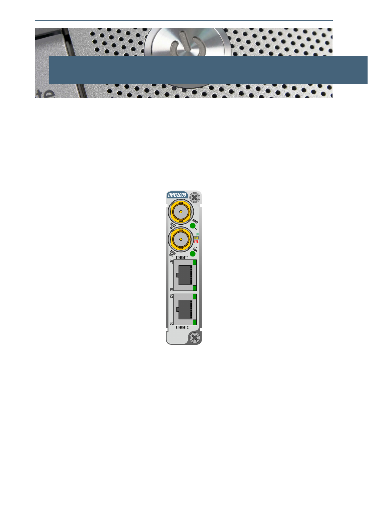
The arrangement of the front panel connectors of the IMB2000C01 module is shown in
the following figure.
Front panel of the IMB2000C01
12

Albalá Ingenieros | Manual IMB2000C01
The IMB2000C01 module provides one input and one output for MADI digital audio and
the electrical Ethernet interfaces.
•MADI IN and MADI OUT are the input and output BNC connectors, respectively, for
AES10 standard signals, better known as MADI.
•ETHERNET 1 and ETHERNET 2 are the Ethernet interfaces used to transmit and receive
audio streams as per the AES67 standard. They are also used to synchronize the device
using IEEE std 1588.
The front panel has not been designed to support mechanical stress. All cabling in the
rack where the mounting frame is located should be properly supported so that the front
panel does not provide mechanical support.
3.5.1. Ethernet connections
The Ethernet connections are made using RJ-45 connectors. The cabling used to make
the UTP connection should be Category 5 or higher (5e or 6) in order to guarantee
proper operation at 1 Gbps.
3.5.2. MADI audio electrical connections
The electrical connectors for MADI audio are all BNC type. The following are a series of
recommendations to keep in mind when making these electrical signal connections.
The BNC connectors used on the cables should be able to handle high frequency
digital audio signals, and it is highly recommended that a manufacturer of recognized
quality be used.
The coaxial cable used should be Belden 1694A or similar. This type of cable achieves
the greatest reach and is also the cabling type for which the equalizers in the
IMB2000C01 are designed. The cables that transport the signal between the module
and other devices should preferably be of a single section, avoiding "barrel"
female-female joiners and multi-section cable runs. If a run of cable must be divided
in two, the same type of cabling should be used for both sections.
RG-59 or similar cables meant for analog video are not recommended for digital audio
unless the lengths are very short.
13

Albalá Ingenieros | Manual IMB2000C01
IMB2000C01
14
Albalá Ingenieros | Manual IMB2000C01
4. OPERATION
This section describes the significance of the front panel indicators of the IMB2000C01
module and their remote control and monitoring ability.
4.1. Front panel description
The appearance of the front panel and the elements it contains are shown in the
following illustration.
Front panel of the IMB2000C01
In addition to the connectors previously described in the Interconnection section the
front panel includes the following indicators and controls:
MADI: This LED lights up in green (OK) to indicate that a MADI signal with the correct
format is being received.
This LED lights up in red (FAIL) when either no MADI signal is being received or if
the format is incorrect.
If this interface is not being used, its status LED can be disabled by turning off the
corresponding reception mask.
15

Albalá Ingenieros | Manual IMB2000C01
AUD.: This LED lights up in green (OK) to indicate that the routing of the channels is
correct. This means that all the interconnections have a valid origin that is either
AES67, MADI or the S2M line of the AUDIOFLEX bus and a valid destination that is
either AES67, MADI or the M2S line of the AUDIOFLEX bus.
This LED lights up in yellow (UNL.) to indicate that the routing of the channels is
correct but the IMB2000C01 module is not correctly synchronized to PTP.
This LED lights up in red (FAIL) to indicate that the routing of the audio channels is
not correct, either because no audio is being received from any of the sources or
because audio cannot be transmitted to any of the destinations.
4.2. Functional description
This section will describe the various interfaces and modules that form the IMB2000C01
in detail.
4.2.1. MADI encoder decoder (CODEC)
The MADI decoder detects, the presence of signal at the MADI input connector,
indicates the number of channels contained in the stream (56 or 64), if the format of
the stream received conforms to AES10 and routs the stream to the interconnection
matrix.
The encoder receives the audio channels to be transmitted from among the 256 that
are received via AES67, MADI or the S2M line of the AUDIOFLEX bus from the
interconnection matrix and generates a MADI stream of 56 or 64 channels as
selected by the user.
4.2.2. AES67 transmitter
The AES67 transmitter can send up to eight streams of a maximum of eight channels
each simultaneously. The name, Ethernet interface to use for transmission, stream
type (unicast or multicast), IP address and port, the number of channels from 1 to 8,
the ID payload and packet time (between 0.125 and 4ms) are all configurable for each
stream.
The audio channels that make up each stream are selected via an interconnection
matrix from among the 256 channels received over AES67, MADI or the S2M line of
the AUDIOFLEX bus.
16

Albalá Ingenieros | Manual IMB2000C01
4.2.3. AES67 receiver
The AES67 receiver can receive up to 16 streams of a maximum of eight channels
each. The parameters that can be configured for each stream are similar to those of
the transmitter, but also include the buffer size used for each stream. In order to
simplify the configuration process and avoid errors, the IMB2000C01 provides a series
of discovery protocols that allow automatic configuration of each receiver via SAP,
DNS-SD or NMOS.
The 128 audio channels accepted by the receiver are routed to the interconnection
matrix.
4.2.4. AUDIOFLEX bus matrix
The AUDIOFLEX bus is formed by two lines, M2S (Master to Slave) and S2M (Slave to
Master), that interconnect all the slots of the UR2000 mounting frame. Each of the
two lines can multiplex up to 64 audio channels sampled at 24 bits and 48kHz.
The 64 audio channels from each line of the AUDIOFLEX bus are grouped into eight
time slots, each of which contains eight audio channels. The insertion or extraction of
the eight audio channels contained in a slot on the bus are always performed by the
same module.
In order to correctly identify all of the different time slots, there must always be a
module installed in the UR2000 frame that acts as the bus master. This is normally
the IMB2000C01, which inserts a header aligned in the M2S line and a reference
signal onto the internal 13.5MHz synchronization bus.
When the IMB2000C01 is installed in a mounting frame, it always acts as the bus
master. In addition to generating the header and the reference signal, it inserts audio
into the eight time slots of the M2S line in order to send it to other modules in the
chassis and to permit extraction of the audio that other modules in the frame have
inserted onto the S2M line.
The TL2000 family modules that have an interface with the AUDIOFLEX bus but do
not generate the alignment header as designated as slaves. These can be divided into
two groups, depending upon their functions: the inserters take audio from external
sources and send it to the S2M line of the bus, whereas the extractors take audio
present in the M2S line of the bus in order to deliver that audio to other devices.
The following modules are capable of inserting audio into the S2M line of the bus:
- ADB2008C01: inserts eight channels of analog audio into a time slot.
-DDB2008C01: inserts eight pairs of AES/EBU digital audio synchronized to the
audio on the bus into two time slots.
-DEB2008C01: inserts eight pairs of AES/EBU digital audio that may or may not be
synchronized to the audio in the bus into two time slots.
17

Albalá Ingenieros | Manual IMB2000C01
The following modules can extract audio from the M2S line of the bus:
-DAB2008C01: reads the eight channels in a time slot and converts them to analog
format.
-DDB2008C01: reads the 16 channels in two time slots and encodes them as eight
pairs of AES/EBU digital audio, synchronized to the audio in the bus.
-DEB2008C01: reads the 16 channels in two time slots and encodes them as eight
pairs of AES/EBU digital audio, synchronized to the audio in the bus, or reads the
eight channels of audio in a time slot and encodes them as four pairs of AES/EBU
digital audio that are not synchronized to the audio in the bus.
The 64 channels of audio that are sent to the M2S line of the AUDIOFLEX bus can be
chosen from among the 256 channels received via AES67, MADI or the S2M line of the
AUDIOFLEX bus.
4.2.5. Synchronization
As with all devices that manage digital audio, the IMB2000C01 module requires a
reference signal to synchronize to. In the case of the IMB2000C01 this synchronization
must be performed using IEEE std 1588, also known as PTP because it is specified in
the AES67 standard. In order to synchronize properly, one of the two Ethernet
interfaces included on the module must have one or more IEEE std 1588 masters. In
addition, the LAN over which the synchronization is performed must provide
sufficient quality of service for synchronization. To achieve this, it is recommended
that the devices forming the LAN be capable of operating as Transparent Clocks or
Boundary Clocks.
The IMB2000C01 includes predefined profiles for its most common applications, and
a customized profile can also be defined with the most relevant protocols for a
specific application.
The signals generated by the IMB2000C01 are synchronized to the other signals
generated in a given installation. In those cases where a piece of equipment does not
have an external reference input a sampling frequency converter such as the
DEB2008C01 must be employed.
The IMB2000C01 uses the reference obtained via IEEE std 1588 to generate a 13.
5MHz reference signal on another internal bus of the mounting frame that is used by
the slave modules for synchronization. Until the slaves have locked to this reference
signal they will not insert nor extract audio to or from the AUDIOFLEX bus.
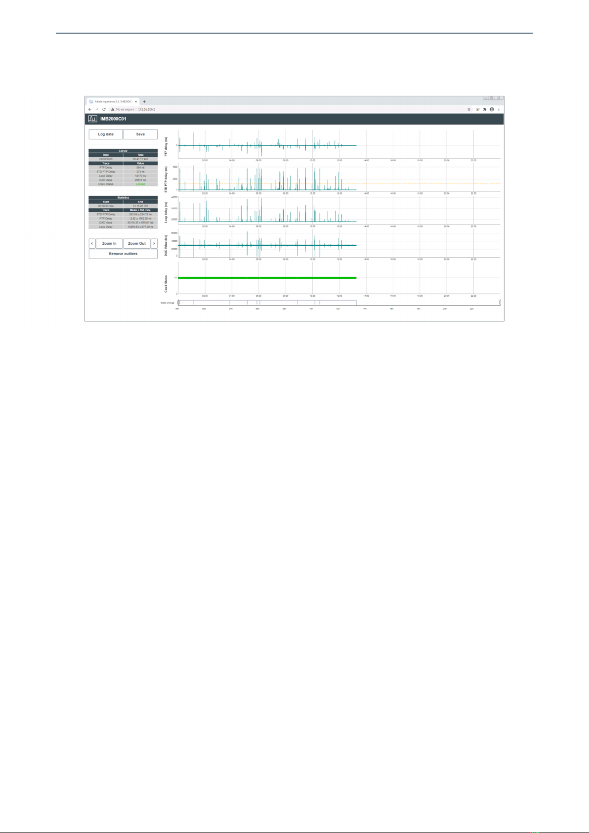
In addition to the synchronization information provided y the control software, the
IMB2000C01 provides a web application through which its synchronization operation
can be monitored over time. This is done by monitoring a history of the most relevant
information related to the synchronization PLL. The following figure shows this
application, which can be accessed from a web browser via Port 80 of either of the
two Ethernet interfaces.
18
Albalá Ingenieros | Manual IMB2000C01
4.2.6. Interconnection matrix
The IMB2000C01 module has a non-blocking interconnection matrix with 256 inputs
and 192 outputs with complete connectivity that is organized as follows:
• Inputs:
AUDIOFLEX S2M: Eight time slots by eight channels per slot.
MADI RX: 64 channels.
AES67 RX: 16 streams by eight channels per stream.
• Outputs:
AUDIOFLEX M2S: Eight time slots by eight channels per slot.
MADI TX: 64 channels.
AES67 TX: 16 streams by eight channels per stream.
4.3. Presets
The IMB2000C01 provides 16 presets what are stored in non-volatile memory and can be
recalled at any time via remote control with a control keyboard or through the control
software installed on a PC.
19

Albalá Ingenieros | Manual IMB2000C01
HUB/SWITCH
TL2000
COMMUNICATIONS
CONTROLLER MODULE
OTHER TL2000
MODULES
Ethernet
Ethernet
Ethernet
Ethernet
REMOTE CONTROL UNIT
TLE2001 PSU2000 PSU2000
TLE2001 PSU2000 PSU2000
UR2000 INTERNAL BUS
UR2000 INTERNAL BUS
Module remote control and supervision
4.4. Module remote control and supervision
The IMB2000C01 requires remote control for configuration.
In order to perform remote configuration and supervision of the module an optional
TL2000 family remote communications controller must be installed in the mounting
frame.
The main function of the communications control module is to interface between a
10/100 Ethernet port and the internal bus of the mounting frame. The following
illustration shows the most common control situations: from a computer or control
panel via Ethernet.
Certain communications control modules provide additional, more advanced functions
such as an SNMP agent, logging of status changes of the modules and a Web interface
for remote control, etc.
Software for simple configuration and supervision with a GUI for multiple modules can
be downloaded from the Albalá Ingenieros website.
20
Table of contents


