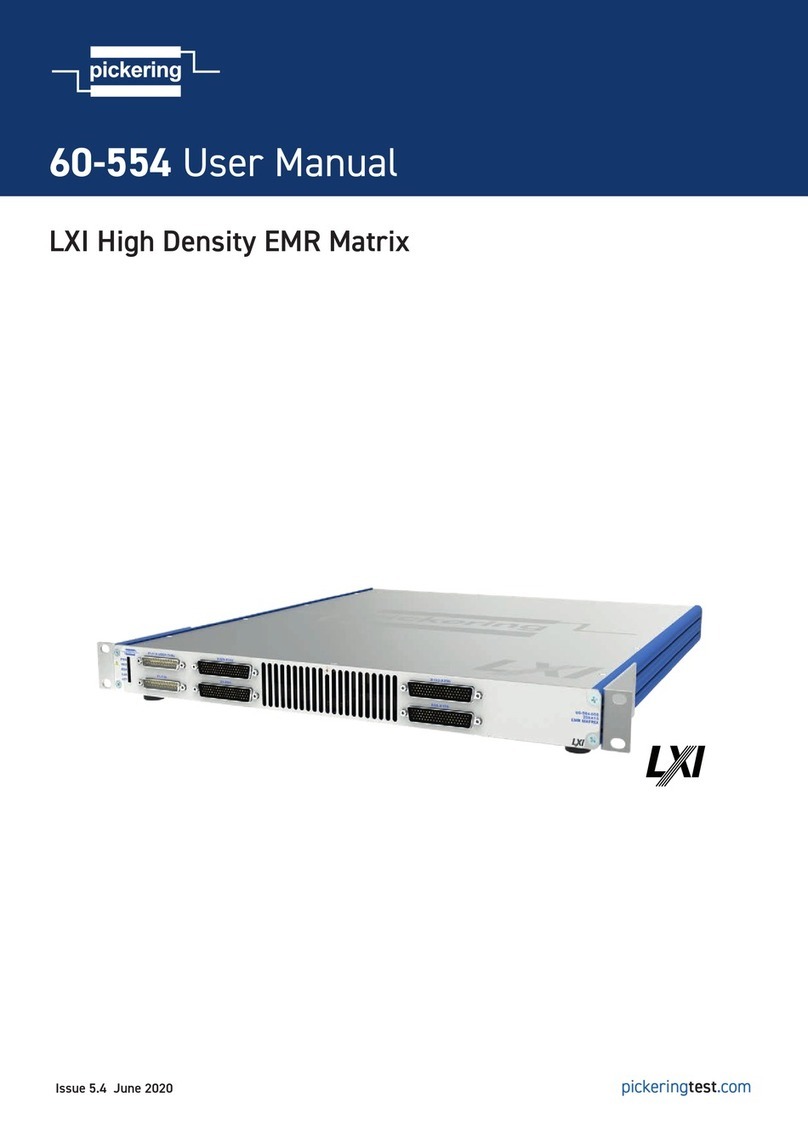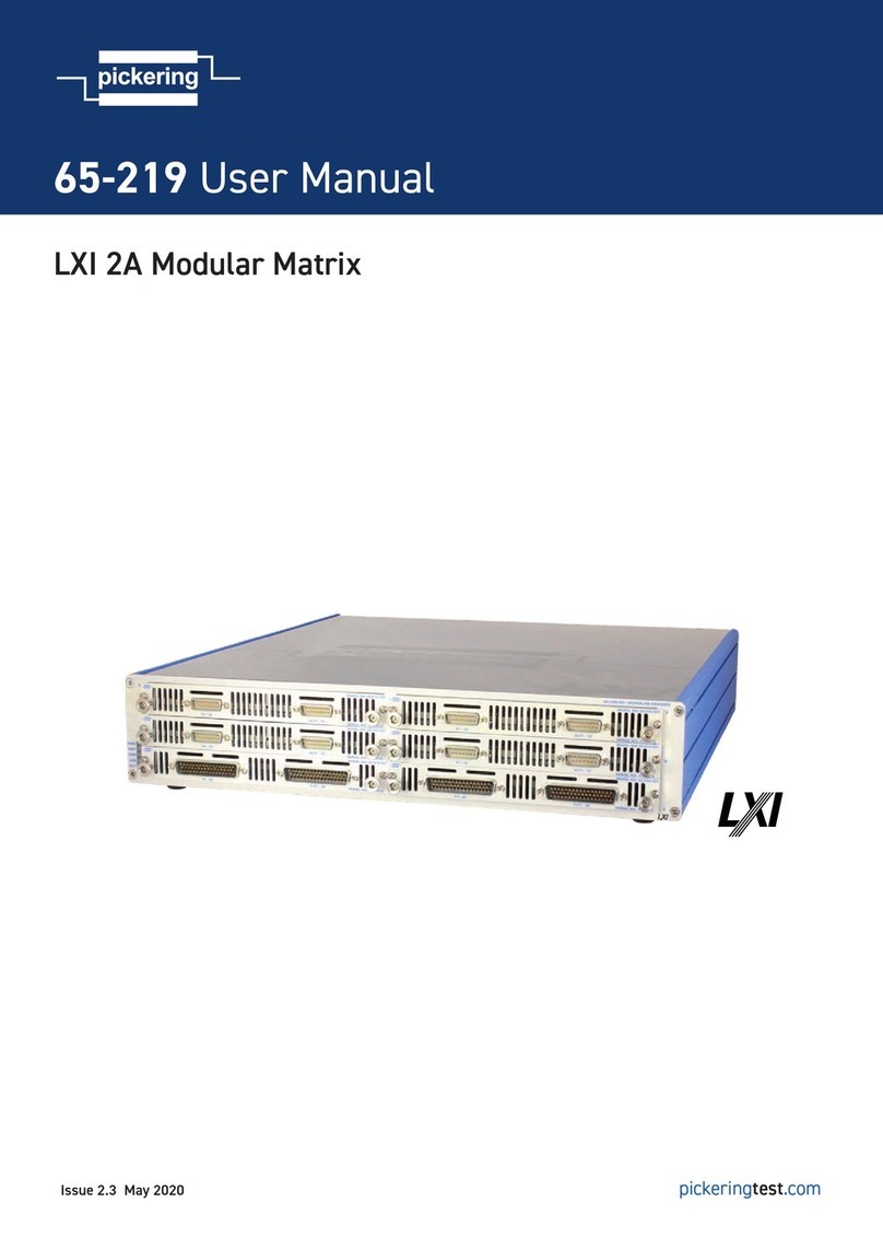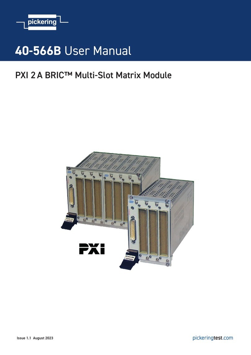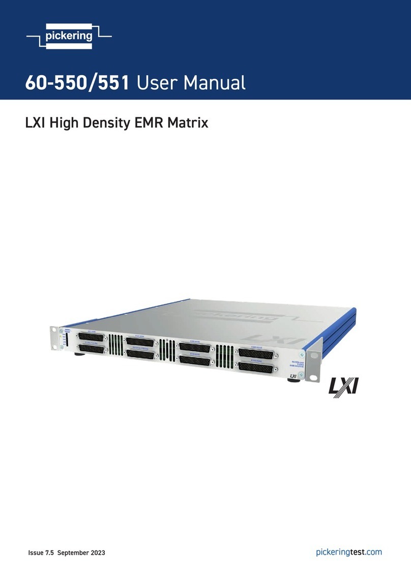
Page 1.1
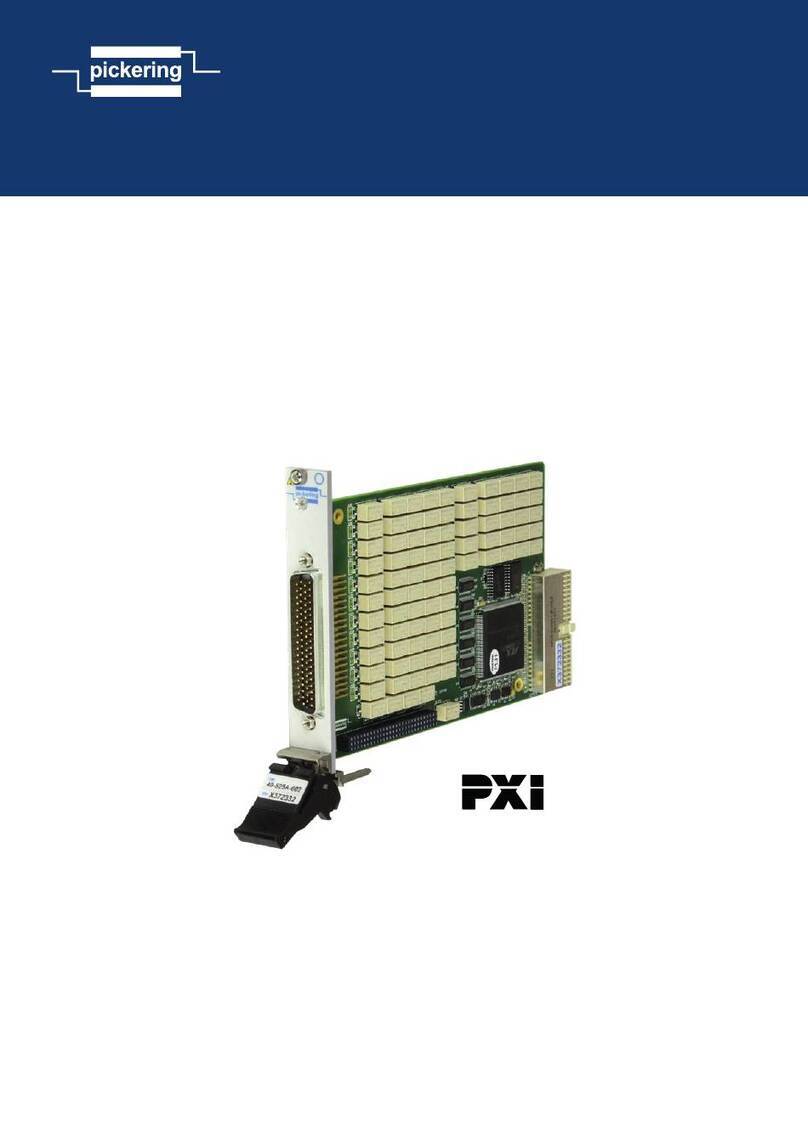
HIGH DENSITY SWITCHING MATRIX MODULE 20-534A
pickering SECTION 1 - TECHNICAL SPECIFICATION
SECTION 1 - TECHNICAL SPECIFICATION
pickeringtest.com
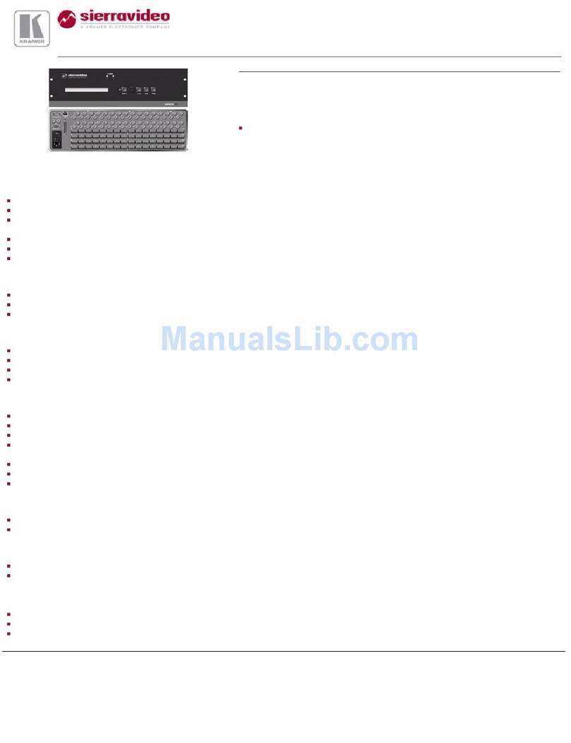
GPIB Very High Density Switching Matrix 20-534A/535A
ISSUE 5.2 JUL 2019
• Very High Density Matrix Modules
• 32 x 8 Single Or Double Pole Matrix Format
• 64 x 4 Single Or Double Pole Matrix Format
• Modules Cascadable to Any Size Using
Internal 24 Pole Analogue Bus
• Automatic Isolation Switching for Maximized
Performance
• Built-In Switch Self Test with Fault Diagnosis
to Component Level
• Switch up to 100 Volts DC, 0.5 Amps (1.2A
carry), 20W Max Power
• Ruthenium Reed Relays For Maximum
Switching Performance
Switching Diagram for the 20-535A
32 x 8 Matrix, Available as Single or
Double Pole
Switching Diagram for the
20-534A 64 x 4 Matrix, Available
as Single or Double Pole
X 1
X 4
Isolation
Switch
X 2
X 3
X 5
X 6
X 7
X 62
X 8
Matrix
Crosspoint
X 63
X 64
Isolation
Switch
Y 2Y4
X 1
X 4
Y 1Y3
X 2
X 3
X 5
X 6
X 7
X 30
X 8
X 31
X 32
Y 8Y 5 7
Isolation
Switch
Matrix
Crosspoint
6YY
The highest density System 20 double pole matrices currently
available from Pickering Interfaces. The 20-534A range of 64 x 4 and
20-535A range of 32 x 8 matrix modules include automatic isolation
switching, plug-in expansion and built-in self-test to give complete
switching condence.
Models 20-534A (64x4) and 20-535A (32x8) now give the highest
density 1 or 2 pole matrices available in any Pickering Interfaces
System 20 switching module. They are intended for easy construction
and use of large matrix systems; modules may be easily expanded to
form matrices of almost any size, e.g. 64 x 4, 128 x 4, 256 x 8 ....512 x
16 using model 20-534; and 32 x 8, 64 x 8, 128 x 16....256 x 32 using
model 20-535A.
Main applications are for signal routing in ATE systems: between the
device under test and the measurement and stimulus instruments.
Connections are made via front panel mounted connectors. Larger
matrices may be constructed using the internal 24 pole analogue bus.
Isolation Switches on each module remove
all unused columns and rows from the system,
hence keeping interconnection capacitance,
leakage and crosstalk to an absolute
minimum.
Creating Larger Matrices - Easily!
Each System 20 interface can directly support
matrices with over 10 000 crosspoints. Larger
sizes are supported using multiple System
20 interface modules. Large matrices are
constructed by interconnecting two or more
matrix modules. All such matrix modules must
have the same primary address. Their position
within the matrix is determined by their bank
address, this is set on an additional 5 way dip
switch.
Both the X and Y axes have on-board
automatic isolation switches.In large
matrix systems the parasitic capacitance
and leakage associated with each crosspoint
switch can result in a signicant degradation
if several matrix modules are interconnected. The isolation switches
connect only those columns and rows on a module that contain an
active relay. Thereby keeping matrix capacitance to a minimum. These
isolation switches are also used to remove the matrix from the external
circuit when performing self-test.
A shielded 24 pole analogue bus is provided on the System 20
Analogue Backplane so constructing large matrices is very straight
forward, no time consuming daisy-chained wiring harnesses etc.
Pickering can build large Matrix systems constructed and tested to
your exact requirements, please contact sales ofce for further details.
*Please contact Pickering for alternative
PXI/LXI/USB solutions
*

