DeDietrich BESL 400 User manual

UNO EN
Solar hot water calorifer
BSL 200...400
BESL 200...400
L000541-B
User Guide
300028413-001-A

Contents
1 Introduction ................................................................................................4
1.1 Symbols used .......................................................4
1.1.1 Symbols used in the manual ...................................4
1.1.2 Symbols used on the equipment .............................4
1.2 Abbreviations ........................................................4
1.3 General ..................................................................5
1.3.1 Manufacturer's liability .............................................5
1.3.2 Installer's liability .....................................................5
1.3.3 User's liability ..........................................................5
1.4 Homologations ......................................................6
1.4.1 Certifications ...........................................................6
2Safety instructions and recommendations ..............................................7
2.1 Safety instructions ...............................................7
2.2 Recommendations ................................................7
3Technical description ................................................................................9
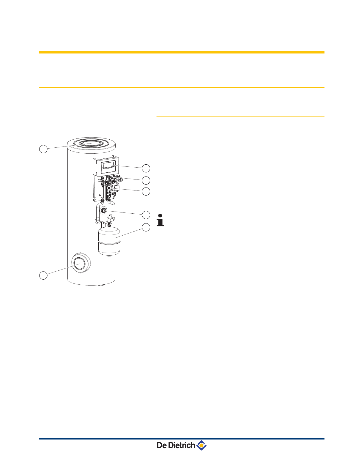
3.1 Main parts ..............................................................9
3.1.1 Solar domestic hot water calorifier ..........................9
3.2 Control panels .....................................................10
3.2.1 Description of the keys ..........................................10
3.2.2 Description of the display ......................................11
4 Operating the appliance ..........................................................................13
4.1 Reading out measured values ...........................13
4.1.1 Resetting the values to zero ..................................13
4.2 User settings .......................................................14
4.2.1 Setting the time .....................................................14
4.2.2 Force back-up .......................................................14
4.2.3 Modifying the back-up authorisations ....................14
4.2.4 In the event of prolonged absences ......................14
4.3 Setting the DHW calorifier outlet
temperature .........................................................15
4.3.1 Programming and setting the electrical back-
up ..........................................................................15
4.3.2 Setting the thermostatic mixing valve ....................16
111/06/2012 - 300028413-001-A

4.4 Starting and stopping the control system ........16
5 Checking and maintenance .....................................................................17
5.1 General instructions ...........................................17
5.2 Safety valve or safety unit .................................17
5.3 Cleaning the casing material .............................17
5.4 Checking the magnesium anode .......................17
6 Troubleshooting .......................................................................................18
6.1 Incidents and solutions ......................................18
7 Technical specifications ..........................................................................19
7.1 Solar domestic hot water calorifier ...................19
7.2 Composition of the NF CESI solar systems
packages (For France) .......................................20
8 Warranty ....................................................................................................23
8.1 General ................................................................23
8.2 Warranty terms ...................................................23
Contents
211/06/2012 - 300028413-001-A

311/06/2012 - 300028413-001-A

1 Introduction
1.1 Symbols used
1.1.1. Symbols used in the manual
In these instructions, various danger levels are employed to draw the
user's attention to particular information. In so doing, we wish to
safeguard the user's safety, obviate hazards and guarantee correct
operation of the appliance.
DANGER
Risk of a dangerous situation causing serious physical
injury.
WARNING
Risk of a dangerous situation causing slight physical
injury.
CAUTION
Risk of material damage.
Signals important information.
¼ Signals a referral to other instructions or other pages in the
instructions.
1.1.2. Symbols used on the equipment
Before installing and commissioning the device, read
carefully the instruction manuals provided.
Dispose of the used products in an appropriate recovery
and recycling structure.
1.2 Abbreviations
4CFC: Chlorofluorocarbon
4DHW: Domestic hot water
BSL 200...400 BESL 200...400 1. Introduction
11/06/2012 - 300028413-001-A 4

1.3 General
1.3.1. Manufacturer's liability
Our products are manufactured in compliance with the requirements
of the various applicable European Directives. They are therefore
delivered with [ marking and all relevant documentation.
In the interest of customers, we are continuously endeavouring to
make improvements in product quality. All the specifications stated in
this document are therefore subject to change without notice.
Our liability as the manufacturer may not be invoked in the following
cases:
4Failure to abide by the instructions on using the appliance.
4Faulty or insufficient maintenance of the appliance.
4Failure to abide by the instructions on installing the appliance.
1.3.2. Installer's liability
The installer is responsible for the installation and inital start up of the
appliance. The installer must respect the following instructions:
4Read and follow the instructions given in the manuals provided
with the appliance.
4Carry out installation in compliance with the prevailing legislation
and standards.
4Perform the initial start up and carry out any checks necessary.
4Explain the installation to the user.
4If a maintenance is necessary, warn the user of the obligation to
check the appliance and maintain it in good working order.
4Give all the instruction manuals to the user.
1.3.3. User's liability
To guarantee optimum operation of the appliance, the user must
respect the following instructions:
4Read and follow the instructions given in the manuals provided
with the appliance.
4Call on qualified professionals to carry out installation and initial
start up.
4Get your installer to explain your installation to you.
4To carry out inspections and maintenance required by a qualified
professional.
4Keep the instruction manuals in good condition close to the
appliance.
1. Introduction BSL 200...400 BESL 200...400
511/06/2012 - 300028413-001-A

This appliance is not intended to be used by persons (including
children) whose physcial, sensory or mental capacity is impaired or
persons with no experience or knowledge, unless they have the
benefit, through the intermediary of a person responsible for their
safety, of supervision or prior instructions regarding use of the
appliance. Care should be taken to ensure that children do not play
with the appliance.
1.4 Homologations
1.4.1. Certifications
This product complies to the requirements to the european directives
and following standards:
42006/95/EC Low Voltage Directive.
Reference Standard: EN 60.335.1.
42004/108/EC Electromagnetic Compatibility Directive.
Reference Standards: EN 50.081.1, EN 50.082.1, EN 55.014
BSL 200...400 BESL 200...400 1. Introduction
11/06/2012 - 300028413-001-A 6

2 Safety instructions and
recommendations
2.1 Safety instructions
DANGER
If smoke is released or in case of refrigerant leak:
1. Switch the appliance off.
2. Open the windows.
3. Evacuate the premises.
4. Contact a qualified professional.
CAUTION
Do not neglect to service the appliance. Contact a qualified
professional or take out a maintenance contract for the
annual servicing of the appliance.
CAUTION
Before any work, switch off the mains supply to the
appliance.
2.2 Recommendations
WARNING
Only qualified professionals are authorised to work on the
appliance and the installation.
Never drain the installation. Do not replace or add water
or solar fluid to the installation. These actions must be
carried out by a qualified technician
To take advantage of the guarantee, no modifications must be made
to the appliance. Only remove the covers for maintenance and
breakdown repair operations and put the covers back in place after
the maintenance and breakdown repair operations.
Instructions stickers
The instructions and warnings affixed to the appliance must never be
removed or covered and must remain legible during the entire lifespan
of the appliance. Immediately replace damaged or illegible
instructions and warning stickers.
2. Safety instructions and recommendations BSL 200...400 BESL 200...400
711/06/2012 - 300028413-001-A

WARNING
Never cut the power to the solar control system, even
during extended absences. The control system protects
the installation against overheating in summer when it is
running.
WARNING
Do not modify the control system parameters unless fully
conversant with them.
During extended absences, we recommend lowering the set point
temperature in the solar DHW calorifier to 45°C. When the user is
present, the set point must be set to 60°C.
BSL 200...400 BESL 200...400 2. Safety instructions and recommendations
11/06/2012 - 300028413-001-A 8

3 Technical description
3.1 Main parts
3.1.1. Solar domestic hot water calorifier
BSL 200...400: External view
AExpansion vessel
ZTop inspection trap
ESide inspection plate
RSolar station
TSolar regulator
YElectrical back-up (Option)
USafety control unit for the solar circuit
All components are checked for leaks and tested in the
factory. The control system, the pump and the electrical
back-up are pre-wired.
L000430-C
5
7
4
6
1
2
3
3. Technical description BSL 200...400 BESL 200...400
911/06/2012 - 300028413-001-A

BESL 200...400: External view
AExpansion vessel
ZTop inspection trap
ESide inspection plate
RSolar station
TSolar regulator
YElectrical back-up
USafety control unit for the solar circuit
All components are checked for leaks and tested in the
factory. The control system, the pump and the electrical
back-up are pre-wired.
3.2 Control panels
3.2.1. Description of the keys
AKey ) :
4Move the cursor upwards.
4Increase the value of parameter .
BKey B :
4Access a selected parameter.
4Confirm a value modification.
CKey ( :
4Move the cursor downwards.
4Reduce the parameter value.
D 3-position switch:
4E : The back-up may be active in day mode and
night mode.
40: The back-up is deactivated.
4Z : The back-up is active in night mode only.
L000431-C
2
3
5
4
6
1
7
M002759-A
A
B
C
D
BSL 200...400 BESL 200...400 3. Technical description
11/06/2012 - 300028413-001-A 10

3.2.2. Description of the display
nSystem schematics (System-Screen)
ASolar sensor probe
ZSolar collectors
Esolar heating pump
RSolar exchanger
TSolar hot water calorifer
YSolar sensor
UBack-up
IDHW sensor - Back-up
nOperating indicators
Steady symbol Flashing
symbol
State
K Solar pump activated.
% Back-up activated.
Z DHW calorifer set point temperature
exceeded.
KZCooling function of the collector or
DHW calorifer activated.
E Antifreeze function activated.
KEAntifreeze function active (running).
EMinumum collector temperature
exceeded.
a ZMaximum DHW tank temperature
exceeded.
aMaximum collector temperature
exceeded.
T Adjustment parameter.
TChanging the settings.
] a Sensor fault.
R + K a Forcing of the solar pump.
R + %aForcing of the electrical back-up.
M002760-A
1
4 5
2
37
8
6
M002761-A
II I
3. Technical description BSL 200...400 BESL 200...400
11 11/06/2012 - 300028413-001-A

nLED display
ALED
LED message
code
Heating pump status Description
Continuously
green
PUMPE relay is
closed.
Regulation operating normally
(System Operating).
Flashing green/
red
4Initialisation
phase
4Manual mode
4The installation is in
manual mode: Set the
regulator to automatic
mode.
Flashing red 4Sensor fault.
4Maximum tank
temperature
exceeded.
4The hot water tank has
reached the set
temperature and the
installation is in
overheating safety mode
or in cooling mode.
4There is a sensor fault.
M002762-A
A
BSL 200...400 BESL 200...400 3. Technical description
11/06/2012 - 300028413-001-A 12

4 Operating the appliance
4.1 Reading out measured values
Scroll down the values measured using the ( and ) keys.
Parameter Description Remarks
TC Collector temperature S1 sensor.
The value TC shows the temperature in °C given by the collector sensor in real time.
TR Calorifier temperature
(Solar exchanger -
lower)
S2 sensor.
The value TR shows the temperature in °C in real time measured by the sensor in the lower
zone of the DHW calorifier.
THR Calorifier temperature
(Back-up)
S3 sensor.
The value THR shows the temperature in °C in real time measured by the sensor in the
upper zone of the DHW tank.
PC % Pump regime Value PC % gives the solar heating pump regime in real time (0-100%).
tc Auto-calibration time The value tc shows the self-calibration phase time remaining in seconds.
RAP Force back-up On: Back-up powered up.
AUTO: Back-up managed by the control system.
¼ See chapter: "Force back-up", page 14.
h P1 Hour run meter on the
solar pump
Reset to zero possible.
¼ See chapter: "Resetting the values to zero", page 13.
h P2 Hour run meter on the
electrical back-up
Reset to zero possible.
¼ See chapter: "Resetting the values to zero", page 13.
KWh Amount of heat (kWh) 4The amount of heat received is calculated according to the parameters input on
commissioning (DMAX).
4Reset to zero possible.
¼ See chapter: "Resetting the values to zero", page 13.
Values KWh or MWh give an estimate of the total amount of heat produced by the
installation in kWh or MWh since commissioning of the control system. The amount of heat
received is calculated according to the parameters input on commissioning (DMAX).
MWh Amount of heat (MWh)
HRE Time ¼ See chapter: "Setting the time", page 14.
4.1.1. Resetting the values to zero
It is possible to reset the value to zero when the letter T is displayed.
1. Select a value using the ( and ) keys.
2. Press the B key for 2 seconds. The value is reset to zero.
To suspend the operation, do not press any keys for 5
seconds. The control system will automatically go back to
the value display mode.
4. Operating the appliance BSL 200...400 BESL 200...400
13 11/06/2012 - 300028413-001-A

4.2 User settings
4.2.1. Setting the time
1. Select the HRE channel with the ( and ) keys.
2. Press the B key for 2 seconds.
3. Set the hour with the ( and ) keys.
4. Press the B key to confirm.
5. Set the minutes with the ( and ) keys.
6. Press the B key to confirm.
CAUTION
The controller does not switch between summer and
winter time.
4.2.2. Force back-up
1. Select the RAP channel with the ( and ) keys.
2. Press the B key for 2 seconds. The symbol T flashes.
3. Set the RAP parameter to ON using the ) key.
4. Press the B key to confirm the setting.
The electrical back-up shuts down when the set point
temperature is attained.
4.2.3. Modifying the back-up authorisations
Throw the switch to modify the electrical back-up authorisations.
EWinter: Electrical back-up is authorised day and night.
0 Electrical back-up is not authorised. No back-up heating.
ZSummer: Electrical back-up is only authorised at night.
The back-up is deactivated if the solar pump is running.
4.2.4. In the event of prolonged absences
In the event of prolonged absence, shut down the electrical back-up
and reduce the solar calorifier set point:
M002763-A
BSL 200...400 BESL 200...400 4. Operating the appliance
11/06/2012 - 300028413-001-A 14

1. Set the 3-position switch to 0.
2. Advance to the last display channel (HRE) with the ( key.
3. Press the ( key for 5 seconds.
A setting parameter is displayed, with the symbol T.
4. Select parameter SX using keys ) and (.
5. Briefly press the B key.
The symbol T flashes, the parameter can be set.
6. Modify the parameter using the ( and ) keys.
For example 45(°C).
7. Press B to confirm the setting.
nReturn from prolonged absence
On return from a prolonged absence:
4Adjust the set point of the solar calorifier SX to its installation value.
4Re-authorise the back-ups.
4Set the 3-position switch to winter or summer, according to the
season.
4.3 Setting the DHW calorifier outlet temperature
4.3.1. Programming and setting the electrical
back-up
The temperature of the volume of water heated by the electrical
resistor is set by the installer on commissioning of the installation
according to the size of the home.
Using the solar control system, it is possible to adjust the volume of
water heated to 40 °C by the resistor in two ways:
4Force the continuous heating of the resistor for significant
unforeseen needs.
¼ See chapter: "Force back-up", page 14.
4Select winter mode w (2 hours maximum according to the volume
of the domestic hot water required at 40 °C) to compensate for the
lack of sun in winter. If necessary, the period scheduled outside of
the off-peak hours is set between 16:00 and 18:00, i.e at the end
of the day when the solar contribution is reduced and just before
the drawing off period.
¼ See chapter: "Modifying the back-up authorisations", page
14.
I
M002799-A
4. Operating the appliance BSL 200...400 BESL 200...400
15 11/06/2012 - 300028413-001-A

4.3.2. Setting the thermostatic mixing valve
28 Domestic cold water inlet
57 Domestic hot water outlet
The mixing valve is set in the factory for a DHW outlet temperature of
60°C (position 6). To lower this temperature, remove the top cover
and turn the wheel anti-clockwise. In position 1, the outlet temperature
is lowered to 35°C.
Position 1 2 3 4 5 6
Temperature at the mixer valve outlet 35 °C 40 °C 45 °C 50 °C 55 °C 60 °C
4.4 Starting and stopping the control system
CAUTION
If the temperature in the solar collectors is higher than
130°C, the control system operates in safety mode. Wait
until the evening before start-up or cool down (cover) the
solar collectors.
Commissioning is performed by the installer. Once connected to the
power supply, the control system is in automatic mode. To disconnect
the solar pump, a minimum temperature of 30 °C is required at the
collector and a temperature difference of 6 °C with respect to the
domestic hot water calorifier.
If the particular conditions make it necessary to adjust the
settings, contact the installer.
C003732-A
57
28
BSL 200...400 BESL 200...400 4. Operating the appliance
11/06/2012 - 300028413-001-A 16

5 Checking and maintenance
5.1 General instructions
CAUTION
4Maintenance operations must be done by a qualified
engineer.
4Only original spare parts must be used.
5.2 Safety valve or safety unit
The safety valve or unit on the domestic cold water inlet must be
operated at least once a month to ensure proper operating and to
prevent from any overpressure which may that may damage the
domestic hot water calorifier.
WARNING
Failure to abide by this maintenance rule may damage the
domestic hot water calorifier and void its warranty.
5.3 Cleaning the casing material
Clean the outside of appliances using a damp cloth and a mild
detergent.
5.4 Checking the magnesium anode
The magnesium anode must be checked at least every 2 years. After
the first check, determine the frequency of future checks on the basis
of anode wear.
5. Checking and maintenance BSL 200...400 BESL 200...400
17 11/06/2012 - 300028413-001-A

6 Troubleshooting
6.1 Incidents and solutions
Description Checks Solutions
The pilot light is off. The current has been cut. Restore the current.
BSL 200...400 BESL 200...400 6. Troubleshooting
11/06/2012 - 300028413-001-A 18

7 Technical specifications
7.1 Solar domestic hot water calorifier
BSL 200 BSL 300 BSL 400
Primary circuit: Solar exchanger
Maximum operating temperature °C 110 110 110
Maximum operating pressure bar 10 10 10
Exchanger capacity litres 5.6 8.1 10.1
Exchange surface m20.84 1.2 1.5
Primary circuit: Back-up exchanger
Maximum operating temperature °C 110 110 110
Maximum operating pressure bar 10 10 10
Exchanger capacity litres 5.1 5.1 5.1
Exchange surface m20.76 0.76 0.76
Pressure drop at 2 m3/Time kPa 4 4 4
Secondary circuit (domestic water)
Maximum operating temperature °C 95 95 95
Maximum operating pressure bar 10 10 10
Water content litres 225 300 395
Top up volume litres 75 105 150
Solar volume litres 150 195 245
Weight
Gross weight kg 125 125 158
Net weight kg 109 111.5 145
Performance Primary circuit: Back-up exchanger
Power exchanged(1) kW 24 24 24
Performance
Flow per hour (∆T = 35 °C(1) litres per hour 590 590 590
Transfer capacity over 10 minutes (∆T = 30°C)(2) litres per 10 min. 150 200 270
Cooling constant Cr Wh/24h·L·K 0.23 0.20 0.18
Maintenance consumption (ΔT=45K) kWh/24h 1.8 2.2 2.6
Performance NL 0.7 1.2 2.7
(1) Primary temperature: 80 °C - Domestic cold water inlet: 10 °C - Domestic hot water outlet: 45 °C - Primary flow rate: 2 m3/h
(2) Primary temperature: 80 °C - Domestic cold water inlet: 10 °C - Domestic hot water outlet: 40 °C - Domestic hot water storage: 65 °C
BESL 200 BESL 300 BESL 400
Primary circuit: Solar exchanger
Maximum operating temperature °C 110 110 110
Maximum operating pressure bar 10 10 10
Exchanger capacity litres 5.6 8.1 10.1
Exchange surface m20.84 1.2 1.5
Secondary circuit (domestic water)
Maximum operating temperature °C 95 95 95
Maximum operating pressure bar 10 10 10
7. Technical specifications BSL 200...400 BESL 200...400
19 11/06/2012 - 300028413-001-A
This manual suits for next models
5
Table of contents
Other DeDietrich Water System manuals
Popular Water System manuals by other brands

Hellenbrand
Hellenbrand Iron curtain System 2.0 owner's manual

Culligan
Culligan Premier Series Installation, operation and service instructions

Thermo Scientific
Thermo Scientific ADVANCED Series Quick start guides

OMEGA AIR
OMEGA AIR AOK 20SS Installation and operating manual

Crysalli
Crysalli CP2000-R-UC-BH installation guide

DIG
DIG ST100AS installation instructions