1. General Information
.............................................................................................
...............................................................................
.............................................................................................
1-1. Introduction
1-2. Proper use and operation
1-3. Safety notes
2
2
3
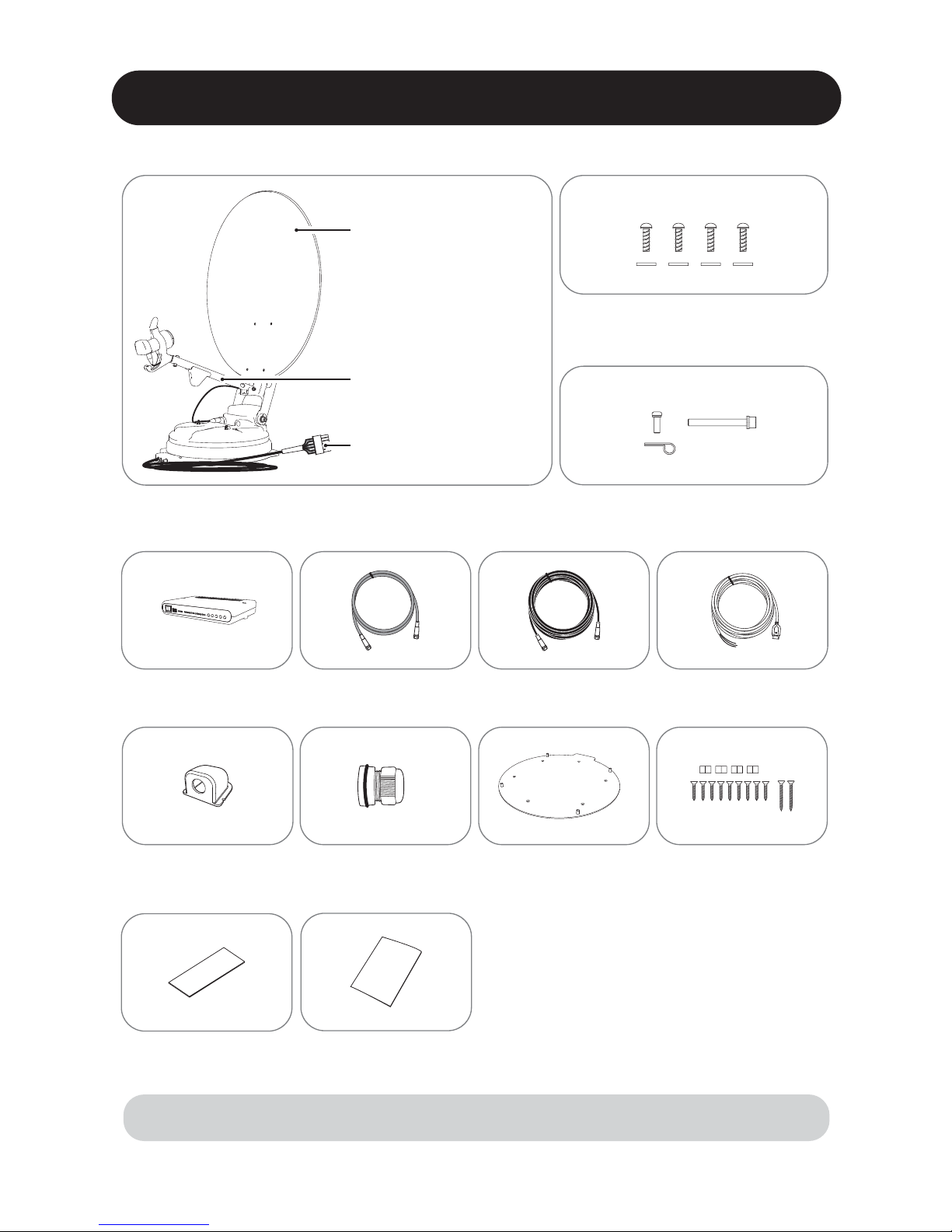
2. Contents
...................................................................................
...........................................................................................
2-1. Components bundle
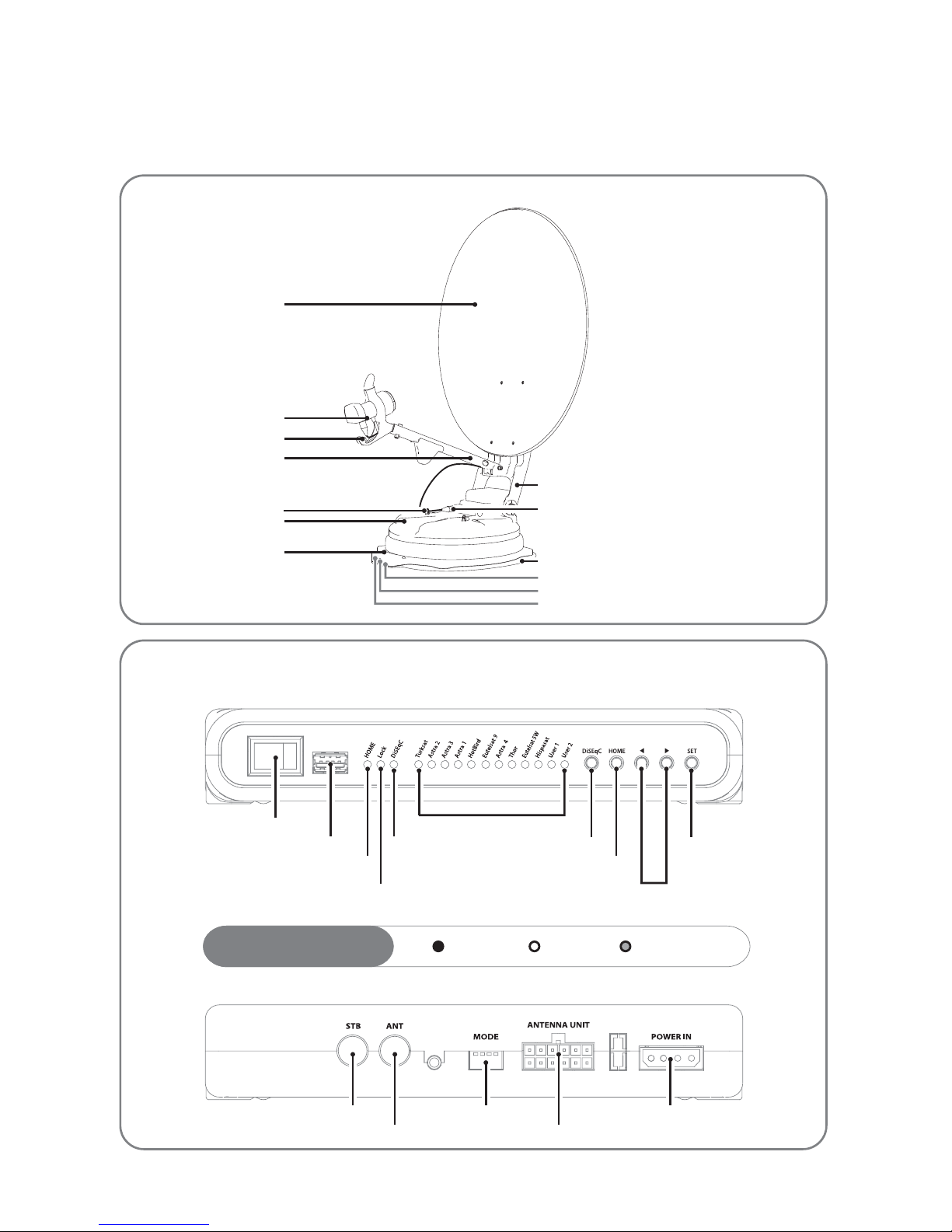
2-2. Name of parts
4
5
10. Caravan/Motorhome installation
...............................................................
.............................................................................
.............................................................................
10-1. Required space for the EASISAT 4.0/4.5
10-2. Equipment for installation
10-3. Instruction for installation
19
21
21
6. Functional description
.........................................................................................
..................................................................................
.......................................................................................
...........................................................................
6-1. Get ready to use
6-2. Searching the satellite
6-3. DiSEqC 1.1 setting
6-4. STB power detection On/O
13
14
14
15
7. Extra functions
9. Specications
...........................................................................................
............................................................................................
.......................................................................................
7-1. Error message
7-2. Factory reset
7-3. Software upgrade
15
16
16
...............................................................................................
............................................................................................
9-1. Dimension
9-2. Specications
18
18
8. Trouble shooting ................................................................................ 17
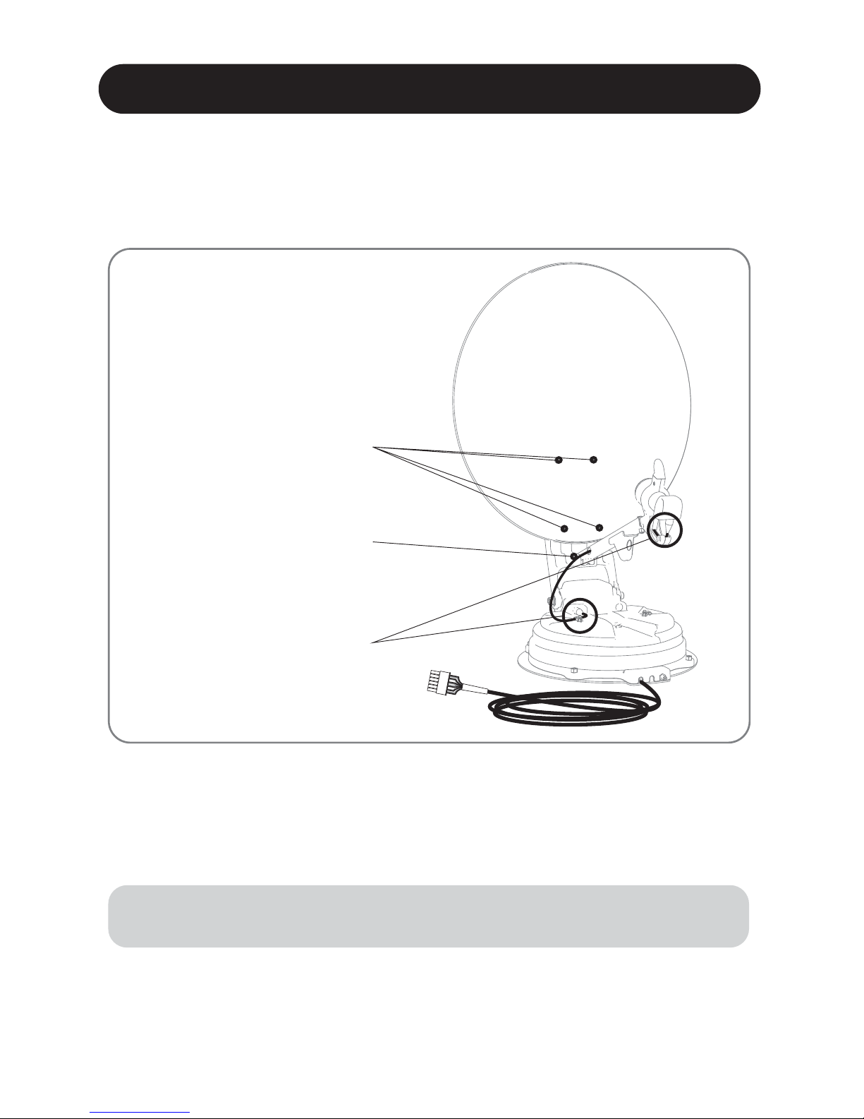
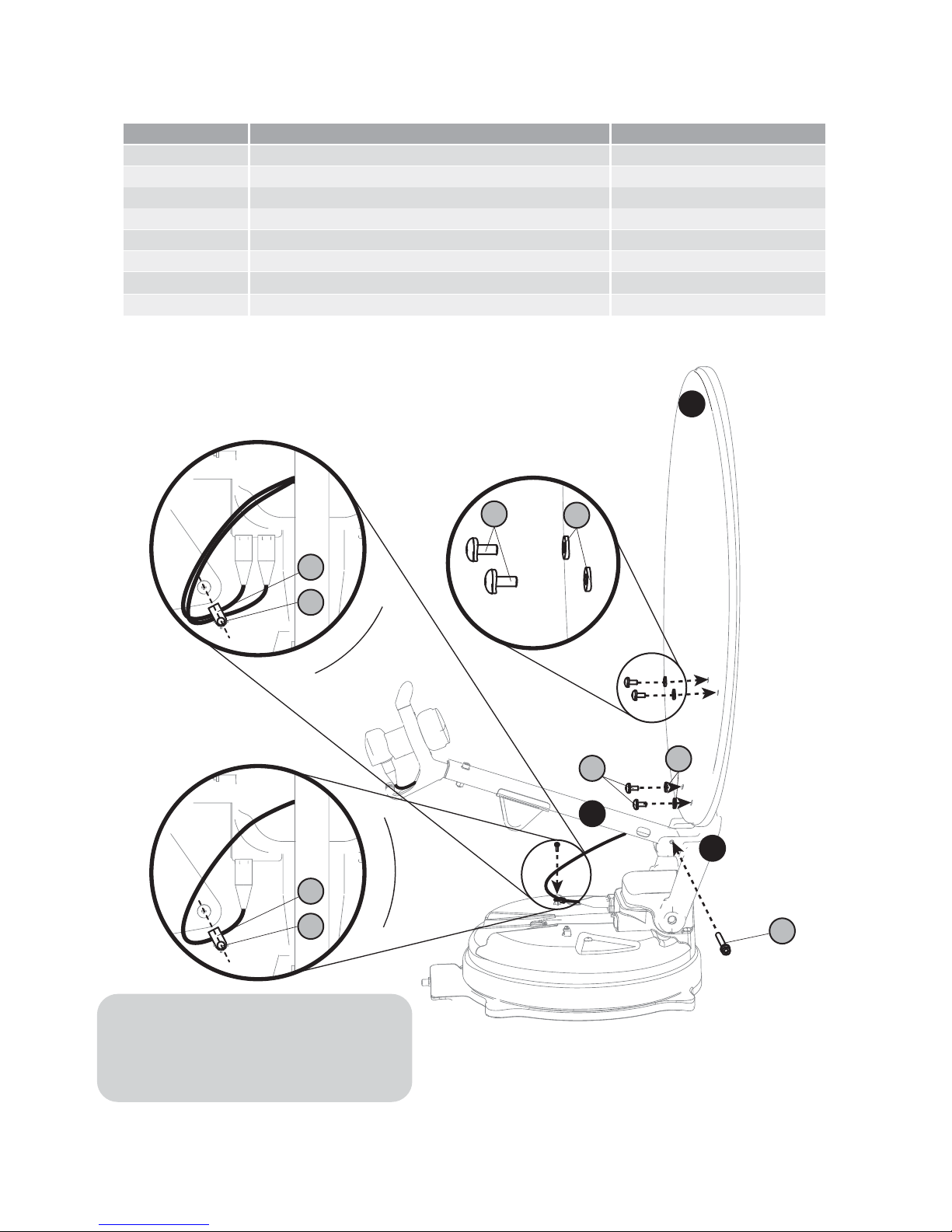
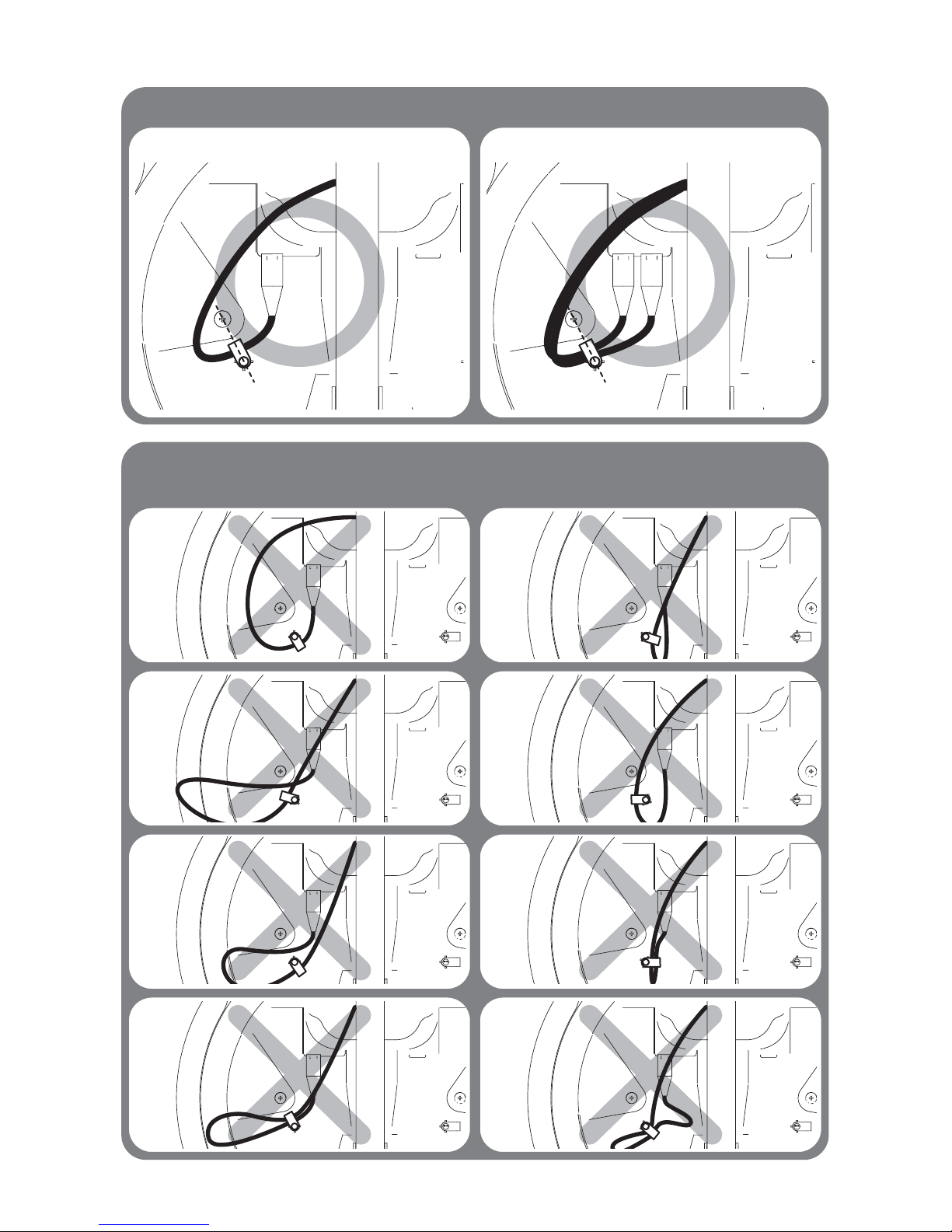
3. How to assemble
4. Connection diagram
5. Skew adjustment
................................................................................
...........................................................................
.................................................................................
6
10
11
Contents