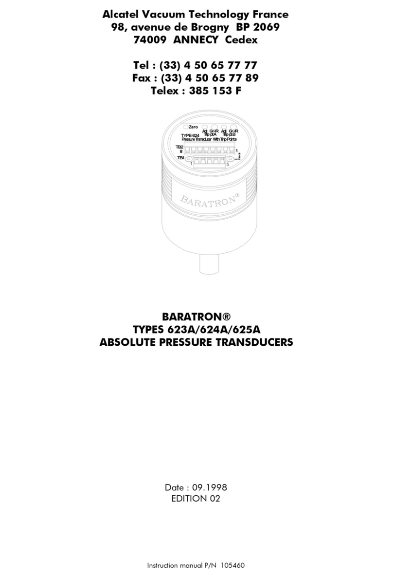
Alcatel Vacuum Technology BARATRON 622A User manual

Alcatel Vacuum Technology France
98, avenue de Brogny BP 2069
74009 ANNECY Cedex
Tel : (33) 4 50 65 77 77
Fax : (33) 4 50 65 77 89
Telex : 385 153 F
T
ype
6
22
Pressure
Transducer
+1
5
VD
C
-
35
mA
PIN SIGNAL
1 Pwr Com
2 Si
g
Com
3 Si
g
Out
p
ut
4 -15 VDC
5 +15 VDC
Chassis
ZERO
ZERO
T
yp
e 62X
Pr
essu
r
e
Tr
a
n
sduce
r
+1
5
VD
C
-
35
mA
PIN SIGNAL
2 Si
g
Out
p
ut
5 Pwr Com
6 -15 VDC
7 +15 VDC
12 Si
g
Com
15 Chassis
BARATRON®
TYPES 622A/626A/627A/628A
ABSOLUTE PRESSURE TRANSDUCERS
Date : 09 .1998
EDITION 02
Instruction manual P/N/ 105459

ii 105459 - Ed 02
For more information or literature, contact:
Alcatel Vacuum Technology France
98 av. de Brogny
74009 ANNECY Cedex - France
Phone: (33) 4 50 65 77 77
FAX: (33) 4 50 65 77 89
Copyright © 1996 by MKS, Inc.
All rights reserved. No part of this work may be reproduced or transmitted in any form or by any means,
electronic or mechanical, including photocopying and recording, or by any information storage or retrieval
system, except as may be expressly permitted in writing by Alcatel.
Swagelok®, VCR®, and VCO®are registered trademarks of Swagelok Marketing Co., Solon, OH
Baratron®is a registered trademark of MKS Instruments, Inc., Andover, MA
Inconel ®is a registered trademark of Inco Alloys International, Huntington, WV

Table of Contents
105459 - Ed 02 iii
Table of Contents
QSafety Procedures and Precautions................................................................ 1
QChapter One: General Information.............................................................. 3
QIntroduction .....................................................................................................................3
QHow This Manual is Organized.........................................................................................4
QCustomer Support............................................................................................................4
QChapter Two: Installation ............................................................................ 5
QHow To Unpack...............................................................................................................5
QUnpacking Checklist ........................................................................................................5
QProduct Location and Requirements ..................................................................................8
QFittings ............................................................................................................................8
QSetup...............................................................................................................................9
•Dimensions 10
•Electrical Installation 11
•Interface Cables 12
•Checking the Transducer Zero 13
•Coarse Zero Adjustment 15
QChapter Three: Overview .......................................................................... 17
QGeneral.........................................................................................................................17
QSensor...........................................................................................................................17
QSignal Conditioner/Electronics ........................................................................................18
QChapter Four: Operation .......................................................................... 19
QGeneral.........................................................................................................................19
•Lowest Suggested Pressure Available for Reading 19
•Lowest Suggested Pressure to Use for Control 19
QChapter Five: Maintenance and Troubleshooting ........................................ 21
QGeneral.........................................................................................................................21
QZero Adjustment.............................................................................................................21
QAppendix A: Product Specifications............................................................. 23
QALCATEL Types 622A and 626A .....................................................................................23
QALCATEL Type 627 A .....................................................................................................24
QALCATEL Type 627A 50 mTorr or mbar ..........................................................................25
QALCATEL Type 628A ......................................................................................................26
QAppendix B: CE Declaration of Conformity .................................................. 28

List of Figures List of Tables
iv 105459 - Ed 02
List of Figures
Figure 1: Two Types of Installation ......................................................................................... 6
Figure 2: Metal Single and Double Ferrule Compression-type Vacuum Fittings.......................... 9
Figure 3: Baratron® Capacitive Transducer’s Position ............................................................. 9
Figure 4: Dimensions of the Types 622A, 626A, 627A and 628A Transducers........................ 10
Figure 5: Power, Signal, and Chassis Grounding Scheme ...................................................... 12
Figure 6: Location of the Zero Pot on Transducer Endcaps ..................................................... 14
Figure 7: Location of the COARSE ZERO Adjustment Control ................................................. 15
Figure 8: Analog Output versus Pressure .............................................................................. 20
List of Tables
Table 1: Baratron® and Power Supply Readout compatibility..................................................... 7
Table 2: Cable References ................................................................................................... 11
Table 3: Required Inputs for Types 622A, 626A, 627A and 628A Transducers........................ 11
Table 4: Pinout of Type 622A Transducer ............................................................................. 13
Table 5: Pinout of Types 626A, 627A, and 628A Transducers................................................ 13
Table 6: Highest Pressure Suggested for Proper Zero Adjustment ........................................... 15
Table 7: Suggested Pressures for Reading and Control .......................................................... 19
Table 8: Troubleshooting Chart............................................................................................ 22

Safety Procedures and Precautions
105459 - Ed 02 1
Safety Procedures and Precautions
ALLOW THE UNIT TO WARM UP
If the unit is used to control hazardous gases, they should not be applied before the unit has
completely warmed up.
USE THE PROPER SIGNAL/POWER CABLE
Use only the cable specified for your product. Use only a cable in good condition.
DO NOT SUBSTITUTE PARTS OR MODIFY INSTRUMENT
Do not install substitute parts or perform any unauthorized modification to the instrument. Return
the instrument to an Alcatel and Service Center for service and repair to ensure that all safety
features are maintained.
SERVICE BY QUALIFIED PERSONNEL ONLY
Operating personnel must not remove instrument covers. Component replacement and internal
adjustments must be made by qualified service personnel only.
PURGE THE INSTRUMENT
After installing the unit, or before its removal from a system, be sure to purge the unit completely
with a clean dry gas to eliminate all traces of the previously used vapors.
DO NOT OPERATE IN EXPLOSIVE AMBIENT ATMOSPHERES
To avoid explosion, do not operate this product in an explosive atmosphere unless it has been
specifically certified for such operation.
USE PROPER FITTINGS AND TIGHTENING PROCEDURES
All instrument fittings must be consistent with instrument specifications, and compatible with the
intended use of the instrument. Assemble and tighten fittings according to manufacturer’s
directions.
CHECK FOR LEAK-TIGHT FITTINGS
Before proceeding to instrument set up, carefully check all plumbing connections to the
instrument to ensure leak-tight installation.
KEEP THE UNIT FREE OF CONTAMINANTS

Safety Procedures and Precautions
2 105459 - Ed 02
Do not allow contaminants of any kind to enter the unit before or during use. Contamination
such as dust, dirt, lint, glass chips, and metal chips may permanently damage the unit and nullify
the warranty.
OPERATE AT PROPER PRESSURE
This transducer is designed for use in vacuum applications. It should not be used in applications
where the system may be exposed to greater than 45 psia or 120% of F.S. (whichever is greater).
If an Ultra-Torr or mbar fitting is used, the system pressure should not exceed 1200 Torr or mbar
absolute pressure.
Definitions of WARNING, CAUTION, and NOTE messages used throughout the
manual.
Warning The WARNING sign denotes a hazard. It calls attention to
a procedure, practice, condition, or the like, which, if not
correctly performed or adhered to, could result in injury to
personnel.
Caution The CAUTION sign denotes a hazard. It calls attention to
an operating procedure, practice, or the like, which, if not
correctly performed or adhered to, could result in damage
to or destruction of all or part of the product.
Note The NOTE sign denotes important information. It calls attention to a
procedure, practice, condition, or the like, which is essential to
highlight.

Chapter One: General Information Introduction
105459 - Ed 02 3
Chapter One: General Information
Introduction
The Baratron® Type 622A, 626A, 627A and 628A Absolute Pressure Transducers are part of the
ALCATEL family of general purpose pressure transducers designed to provide accurate, reliable,
and repeatable pressure measurements in the range from 1 KTorr or mbar to as low as 0.1 Torr
or mbar Full Scale (627A and 628A). These instruments operate with ±15 VDC (±5%) input @
35 mA, 250 mA, or 500 mA, depending upon the unit, and provide 0 to 10 VDC output linear
with pressure. All instruments expose only Inconel to the process permitting use with corrosive or
dirty gases and eliminating contamination of the process with transducer materials.
Measurements are independent of gas composition and all of the units have a minimum
measuring range of four decades.
Using the latest single-sided, dual-electrode Inconel®transducer design, coupled with a low
impedance, fixed-frequency bridge signal conditioner, these instruments are capable of
withstanding high overpressure conditions (45 psia) with minimal or no shifts in output over their
range. The advanced bridge signal conditioning technology provides high accuracy and
operation which is extremely temperature-stable at operating pressure.
Protection from RF interference and noisy electrical environments is increased by the use of a
metal case, by internal design elements, and by the use of surge and ESD suppression networks
and RFI filtering on all inputs and outputs.
The Types 622A and 626A transducers have an accuracy of 0.25% of reading (optional 0.15%
of reading), and are identical except for their connectors; the 622A unit has a 5-pin terminal
block connector and the 626A unit has a 15-pin Type «D» connector. These instruments have
been developed for applications requiring a small, economical transducer which delivers accurate
and repeatable measurements with a resolution of 1 x 10⁻⁴ F.S.
The Types 627A and 628A instruments are designed specifically to meet the needs of vacuum
process systems where environmental and process conditions are particularly demanding.
Temperature control of the transducer minimizes the effects of ambient or process temperature
variations typically encountered in process line environments. The 627A transducer controls the
transducer temperature at 45° C and the 628A unit controls the transducer temperature at
100°C, thereby minimizing contamination from the process. The 627A transducer has an
accuracy of 0.12% of reading (0.1 Torr or mbar units have an accuracy of 0.15% of reading),
and the Type 628A transducer has an accuracy of 0.25% of reading.

How This Manual is Organized Chapter One: General Information
4 105459 - Ed 02
How This Manual is Organized
This manual is designed to provide information and instructions in the proper installation,
operation, and maintenance of the 622A, 626A, 627A and 628A Absolute Pressure Transducers.
Product specifications are provided at the end of the manual.
Before installing your absolute pressure transducer in a system and/or operating it,
carefully read and familiarize yourself with all precautionary notes in the
Safety
Procedures and Precautions
section at the front of this manual. In addition, observe
and obey all WARNING and CAUTION notes provided throughout the manual.
Chapter One, General Information, (this chapter) introduces the product and describes the
organization of the manual.
Chapter Two, Installation, explains the environmental requirements and describes how to
mount the instrument in your system.
Chapter Three, Overview, gives a brief description of the instrument and its functionality.
Chapter Four, Operation, describes how to use the instrument and explains all the functions and
features.
Chapter Five, Maintenance and Troubleshooting, provides maintenance and troubleshooting
information.
Appendix A, Product Specifications, lists the specifications of the instrument.
Appendix B, Declaration of conformity
Customer Support
Standard maintenance and repair services are available at all of our regional Alcatel Service
Centers, listed at the end of the manual. Should any difficulties arise in the use of your Type
622A, 626A, 628A or 628A instrument, or to obtain information about companion products
ALCATEL offers, contact any authorized Alcatel and Service Center. If it is necessary to return the
instrument to ALCATEL, please contact an Alcatel Service Center before shipping.
Please refer to the end of this manual for a list of Alcatel Service Centers.
Warning All returns to Alcatel must be free of harmful, corrosive,
radioactive, or toxic materials.

Chapter Two: Installation How To Unpack
105459 - Ed 02 5
Chapter Two: Installation
How To Unpack
ALCATEL has carefully packed the Type 622A/626A/627A/628A unit so that it will reach you in
perfect operating order. Upon receiving the unit, however, you should check for defects, cracks,
broken connectors, etc., to be certain that damage has not occurred during shipment.
Note Do not discard any packing materials until you have completed your
inspection and are sure the unit arrived safely.
If you find any damage, notify your carrier and Alcatel immediately. If it is necessary to return the
unit to Alcatel, call the Alcatel Service Center before shipping. Please refer to the end of this
manual for a list of Alcatel Service Centers.
Unpacking Checklist
Standard Equipment:
•The Type 622A, 626A, 627A or 628A Absolute Pressure Transducer (specified at time of
order).
•The Type 622A transducer comes with a mating connector for the transducer’s 5-pin
terminal block.

Unpacking Checklist Chapter Two: Installation
6 105459 - Ed 02
Optional Equipment:
The Baratron 622A - 626A - 627A - 628A can be installed & operated the following
ways :
POWER SUPPLY
AND DIGITAL
READOUT
(
PDR
)
BARATRON
CAPACITIVE
TRANSDUCER
VACUUM
FITTING
See
p
ara
g
ra
p
h:
"Electrical Installation"
p
a
g
e 11
See
p
ara
g
ra
p
h:
"Setu
p
"
p
a
g
e 9
See
p
ara
g
ra
p
h:
"Fittin
g
s"
p
a
g
e 8
VACUUM
CHAMBER
INSTALLATION WITH A POWER
DISPLAY AND READOUT
(
PDR
)
POWER SUPPLY
VACUUM
CHAMBER
SIGNAL
OUTPUT
CUSTOMER SPECIFIC
INSTALLATION
Figure 1: Two Types of Installation
The Type 622A, 626A, 627A and 628A are compatible with:
•PDR-C-1C, PDR-C-2C, PDR 660B, PR 4000 readouts
Appropriate cables,see Table 2 on page 11.

Chapter Two: Installation Unpacking Checklist
105459 - Ed 02 7
Compatibility table of Baratrons® and Power Display Readouts:
PDR - 1C PDR - 2C PDR 660 B PR 4000
622A zz z z
626A zz z z
627A zz z z
628A zz z
Table 1: Baratron® and Power Supply Readout compatibility
Legend
zPower supply and display
The corresponding PDR can display the pressure information supplied by the gauge,
however as the power requirement of the gauge exceeds the PDR capacity, an external
power supply is necessary.
See Table 3 on page 11 for external power supply specifications.

Unpacking Checklist Chapter Two: Installation
8 105459 - Ed 02
Product Location and Requirements
Types 622A and 626A:
•Ambient operating temperature should remain between 0° C and 50° C (32° F and 122°F)
•Input required is ±15 VDC (±5%) @ 35 mA (maximum) with <20 mV p-p noise and ripple
Type 627A:
•Ambient operating temperature should remain between 15° C and 40° C (59° F and 104° F)
•Input required is ±15 VDC (±5%) @ 250 mA (maximum) with <20 mV p-p noise and ripple
Type 628A:
•Ambient operating temperature should remain between 20° C and 70° C (68° F and 158°F)
•Input required is ±15 VDC (±5%) @ 500 mA (maximum) with <20 mV p-p noise and ripple
For additional product requirements refer to Appendix A, Product Specifications, page 23.
Fittings
The transducer port will easily carry the weight of the transducer. The following is a list of
available fittings.
•½» diameter (12.7 mm) tubulation
•DN 16 ISO-KF
•Swagelok® VCR®(female)
•Swagelok® 8-VCO®(female)
•Mini-CF
Caution ALCATEL
does not warranty
the 622A, 626A, 627A or 628A
transducer when single or double metal ferrule
compression-type vacuum fittings (shown in Figure 2, page
6) are used because damage will occur to the transducer
when improper tightening procedures are followed.

Chapter Two: Installation Setup
105459 - Ed 02 9
Single Ferrule Double Ferrule
Figure 2: Metal Single and Double Ferrule Compression-type Vacuum Fittings
Setup
W
A L C
V
T E L
W
Manufactured by MKS Instruments, Inc.
Connector Side
Flange Side
Figure 3: Baratron® Capacitive Transducer’s Position
Mount the transducer with the inlet port pointing (vertically) downward. Although the unit can be
mounted in any orientation, mounting it as suggested allows any foreign matter entering the
pressure port to fall away from the diaphragm.
Isolate the unit from vibration as much as possible. When not subject to gas damping at low
pressure, the diaphragm may become susceptible to resonance. The 0.1 and 1 Torr or mbar F.S.
units are most sensitive and you should isolate these units from any vibration that exists.
Remember to isolate the vibration through the cable as well as through the port.

Setup Chapter Two: Installation
10 105459 - Ed 02
Dimensions
Note All dimensions are listed in inches with millimeters referenced in
parentheses.
W
A L C
V
T E L
W
Type 622A
(65.0)
2.56 DIA
(80.52)
(36.83)
(12.70)
0.500 DIA
3.17
1.45
0.31
(7.9)
(125.22)
4.93
1.30
3.76
0.500 DIA
3.00 DIA 0.13
(12.7)
(76.2)
(33.02)
(95.50)
(3.30)
5.19
(131.8)
Type 626A
(65.0)
2.56 DIA
(80.52)
(36.83)
(12.70)
0.500 DIA
3.17
1.45
0.13
(3.30)
(120.65)
4.75
Type 627A and 628A Units
Manufactured by MKS Instruments, Inc.
W
A L C
V
T E L
W
Manufactured by MKS Instruments, Inc.
W
A L C
V
T E L
W
Manufactured by MKS Instruments, Inc.
Note: Dimensions are nominal
values in inches (mm referenced)
Figure 4: Dimensions of the Types 622A, 626A, 627A and 628A Transducers

Chapter Two: Installation Setup
105459 - Ed 02 11
Electrical Installation
1- Installation with an PDR, Power Display Readout
Compatible cable
PDR-C-1C PDR-C-2C PDR-660B PR 4000
622A ZC473S3 ZC473S3 ZC112S3 ZC112S3
626A ZC127S3 ZC127S3 ZC259S3 ZC259S3
627A ZC127S3 ZC127S3 ZC259S3 ZC259S3
628A ZC127S3 ZC127S3 consult us ZC259S3
Table 2: Cable References
The cables described above are 3 m long shielded cables:
•To order 6 or 9 m cables : ZCxxxS6 (6 m shielded cables)
ZCxxxS9 (9 m shielded cables)
•For other lenghts, consult Alcatel.
2- Customer specific installation
The 622A, 626A, 627A and 628A transducers require an external power source capable of
supplying the voltages stated in Table 2. Noise and ripple should be less than 20 mV p-p. You
may use any readout device which has input capabilities of less than 0 to greater than 10 VDC,
and impedance greater than 10K ohms.
Note The ground of any external power supply and readout should be the
same as the transducer ground (chassis ground) to minimize any
possible ground loops which can affect the performance and
stability of the system.
Required Inputs for Types 622A, 626A, 627A and 628A Transducers
Input Required Types 622A & 626A Type 627A Type 628A
At Startup ±15 VDC (±5%) @
35 mA
±15 VDC (±5%) @
250 mA
±15 VDC (±5%) @
500 mA
After 1 hour of
operation at 25° C
±15 VDC (±5%) @
35 mA
±15 VDC (±5%) @
150 mA
±15 VDC (±5%) @
350 mA
Table 3: Required Inputs for Types 622A, 626A, 627A and 628A Transducers

Setup Chapter Two: Installation
12 105459 - Ed 02
Readout
Power
Supply
+
-
0 - 10 V Pressure Output
Signal Common
+ 15 V
- 15 V
Power Common
+ 15V 10K 1 F
Chassis
Ground Sensor
Port
The absolute value of the potential difference between
the chassis ground and signal common/power ground
should not exceed 14 Volts.
NOTE: For best results, use a readout with fully
differential inputs.
Multiple Ground
Tie-Point
Figure 5: Power, Signal, and Chassis Grounding Scheme
Interface Cables
Note Braided, shielded cables are required to meet CE Mark
specifications.
For cables connecting to non-ALCATEL products, ALCATEL can provide normal shielding or
braided shielded cable assemblies in a nominal 10’ (3m) length, terminating in flying leads
(pigtail) fashion at both ends. Braided shielded cable assemblies are recommended if the
environment contains high EMI/RFI noise.
The connector pinout is listed on the transducer endcaps and in
Table 4 and Table 5 on page 13.

Chapter Two: Installation Setup
105459 - Ed 02 13
Pinout of Type 622A Transducer
Pin Signal
1 Power Common
2SignalCommon
3SignalOutput
4 - 15 VDC
5 + 15 VDC
Chassis Ground is made by using the screw labeled CHASSIS on the endcap
Table 4: Pinout of Type 622A Transducer
Pinout of Types 626A, 627A, and 628A Transducers
Pin Signal
2SignalOutput
5 Power Common
6 - 15 VDC
7 + 15 VDC
12 Signal Common
15 Chassis Ground
Table 5: Pinout of Types 626A, 627A, and 628A Transducers
Checking the Transducer Zero
Check the transducer zero prior to the initial operation and then periodically as required. The
zero can be set (or reset) by adjusting the zero potentiometer located on the top cover of the
transducer or at the front panel of any Power Supply/Readout which is being used. The unit must
be fully stabilized before you change the zero adjustment. Stabilization is accomplished by
allowing the unit to warm up for approximately:
•15 minutes for Types 622A and 626A instruments
•2 - 4 hours (8 hours for the 0.1 Torr or mbar range) for the Types 627A and 628A
instruments
Pump the unit, with the power on, down to a pressure less than the transducer’s resolution (0.01%
of Full Scale).
Note Once the unit is properly warmed up and stabilized, the zero
adjustment must be made at a pressure less than the transducer’s
resolution (0.01% of F.S.). Low range transducers (0.1 Torr or
mbar) should be pumped for at least one hour after exposure to air
to remove any moisture and to allow the pressure to stabilize.

Setup Chapter Two: Installation
14 105459 - Ed 02
Zeroing a transducer above its stated minimum resolution creates a zero offset relative (or
unique) to the system in which the transducer is located. All subsequent readings are then linear
and accurate relative to the offset value.
Refer to Figure 2, for the location of the zero potentiometer on the Types 622A, 626A, 627A and
628A transducers.
Note If available pressures are not sufficiently low to set the transducer
zero, you may use a vacuum leak detector with sufficient vacuum
pumping (to achieve proper zeroing pressures). In this case, mount
the transducer on the leak detector in the same plane of orientation
as it will be during actual use.
ZEROPotentiometer
Type 622 Type 626 Type 627, 628
Type 622
Pressure
Transducer
+15 VDC-35 mA
PIN SIGNAL
1 Pwr Com
2 Sig Com
3 Sig Output
4 -15 VDC
5 +15 VDC
Chassis
ZERO ZERO
Type 62X
Pressure
Transducer
+15 VDC-250 mA
PIN SIGNAL
2 Sig Output
5 Pwr Com
6 -15 VDC
7 +15 VDC
12 Sig Com
15 Chassis
ZERO
Type 626
Pressure
Transducer
+15 VDC-35 mA
PIN SIGNAL
2 Sig Output
5 Pwr Com
6 -15 VDC
7 +15 VDC
12 Sig Com
15 Chassis
R
R
15
Figure 6: Location of the Zero Pot on Transducer Endcaps
To properly zero a transducer, follow this procedure:
1. Install the transducer a system with a power supply/readout.
2. Power the transducer and allow it to warm up. Warm up time is:
•15 minutes for Types 622A and 626A transducers
•2 - 4 hours for Types 627A and 628A transducers (8 hours for the 0.1 Torr or
mbar range units)
3. Pump the unit down to a pressure below its resolution (refer to Table 6, page 15, for
recommended pressure levels).
4. Using a small screwdriver, adjust the ZERO pot until the readout displays zero (0000).

Chapter Two: Installation Setup
105459 - Ed 02 15
Highest Pressure Suggested for Proper Zero Adjustment
Full Scale Range
(Torr or mbar)
Highest Pressure for Proper Zero
Adjustment (Torr or mbar)
0.1 *< 5 x 10⁻⁶
1 < 5 x 10⁻⁵
10 < 5 x 10⁻⁴
100 < 5 x 10⁻³
1K < 5 x 10⁻²
*Only available with Types 627A, and 628A transducers
Table 6: Highest Pressure Suggested for Proper Zero Adjustment
Coarse Zero Adjustment
All 600 Series transducers provide additional zero range capability through the coarse zero
adjustment feature. The zero potentiometer provides ample control under normal conditions.
Note Use the coarse zero adjustment only if the zero potentiometer fails to
provide sufficient adjustment.
The ‘coarse zero’ control is accessible through the side of the instrument, as shown in Figure 7.
COARSE ZERO
A
djustment
ZERO
Potentiometer
ZERO
Type 62X
Pressure
Transducer
+15 VDC-250 mA
PIN SIGNAL
2 Sig Output
5 Pwr Com
6 -15 VDC
7 +15 VDC
12 Sig Com
15 Chassis
Figure 7: Location of the COARSE ZERO Adjustment Control

Setup Chapter Two: Installation
16 105459 - Ed 02
Follow the steps below to adjust the coarse zero:
1. Install the transducer in a system with a power supply/readout.
2. Turn the transducer on.
3. Be sure the transducer is properly warmed up (refer to page 13 for warm up times)
and pumped down below its resolution (refer to Table 6 page 15, for recommended
pressure levels).
4. For best results, pump the transducer while it is warming up.
5. Center the ZERO pot located at the top of the transducer (adjust the screw to leave an
equal amount of adjustment both clockwise and counterclockwise).
6. Turn the COARSE ZERO’s multi-position switch (located on the side of the unit) to a
position that produces the output signal closest to zero Volts.
7. Re-install the plastic ring.
8. Adjust the ZERO pot (located on the top of the unit) to bring the output to exactly zero
Volts.
This manual suits for next models
3
Table of contents
Other Alcatel Vacuum Technology Transducer manuals