Alcor AU9223 Product manual

1
D
Da
at
ta
a
B
Bo
oo
ok
k
AU9223
USB KVM Controller
Technical Reference Manual
P
Pr
ro
od
du
uc
ct
t
S
Sp
pe
ec
ci
if
fi
ic
ca
at
ti
io
on
n
Official Release
Revision 1.00
Public Nov. 2005
www.DataSheet4U.com

Page 2 of 21
AU9223 USB KVM Controller V1.00
Official Release_ Public
Data sheet status
Objective specification This data sheet contains target or goal specifications for
product development.
Preliminary specification
T
his data sheet contains preliminary data;
supplementary data may be published later.
Product specification This data sheet contains final product specifications.
Revision History
Date Revision Description
Nov. 2005 1.00 Official release
www.DataSheet4U.com

Page 3 of 21
AU9223 USB KVM Controller V1.00
Official Release_ Public
Copyright Notice
Copyright 1998 - 2005
Alcor Micro Corp.
All Rights Reserved.
Trademark Acknowledgements
The company and product names mentioned in this document may be the
trademarks or registered trademarks of their manufacturers.
Disclaimer
Alcor Micro Corp. reserves the right to change this product without prior notice.
Alcor Micro Corp. makes no warranty for the use of its products and bears no
responsibility for any error that appear in this document. Specifications are subject
to change without prior notice
www.DataSheet4U.com

Page 4 of 21
AU9223 USB KVM Controller V1.00
Official Release_ Public
5.3 [Ctrl]+[Alt] mode
Table of Contents
1 Introduction………………………………………………………………
6
1.1 Description………………………………………………………………………………
6
1.2 Features………………………………………………………………………………….. 6
2 Application Block Diagram…………………………………………. 7
3 Pin Assignment………………………………………………………….
8
4 System Architecture and Reference Design………………….. 11
4.1 AU9223 Block Diagram………………………………………………………….. 11
5 Hot Key Definition…………………………………………………….. 12
5.1 [Scroll]++[Scroll] mode……………………………………………………….. 12
5.2 [Caps]++[Caps] mode…………………………………………………………..
12
5.3 [Num]++[Num] mode …………………………………………………………… 13
5.4 [Ctrl]+[Shift] mode………………………………………………………………… 13
6 Electrical Characteristics…………………………………………… 16
6.1 Recommended Operating Conditions……………………………………. 16
6.2 General DC Characteristics…………………………………………………… 16
6.3 DC Electrical Characteristics for 3.3 volts operation…………… 16
6.4 Crystal Oscillator Circuit Setup for Characterization……………. 17
6.5 ESD Test Results…………………………………………………………………..… 17
6.6 Latch-Up Test Results…………………………………………………………….. 18
7 Mechanical Information………………………………………………
20
www.DataSheet4U.com

Page 5 of 21
AU9223 USB KVM Controller V1.00
Official Release_ Public
List of Figures
2.1 Block Diagram………………………………………………………………………………….. 7
3.1 Pin Assignment Diagram…………………………………………………………………..
8
4.1 AU9223 Block Diagram……………………………………………………………………… 11
6.1 Crystal Oscillator Circuit Setup for Characterization……………………….. 17
6.2 Latch-Up Test Results……………………………………………………………………….. 18
7.1 Mechanical Information Diagram……………………………………………………..
20
List of Tables
3.1 Pin Descriptions……………………………………………………………………………. 9
6.1 Recommended Operating Conditions..…………………………………………. 16
6.2 General DC Characteristics………………………………………………………….. 16
6.3 DC Electrical Characteristics for 3.3 volts operation………………….. 16
6.4 ESD Data……………………………………………………………………………………….. 17
6.5 Latch-Up Test Results……………………………………………………………………. 19
www.DataSheet4U.com

Page 6 of 21
AU9223 USB KVM Controller V1.00
Official Release_ Public
1.0 Introduction
1.1 Description
AU9223 is a highly integrated single chip USB KVM controller offering users the
possibility of sharing keyboard, mouse and monitor between two PC. Not like
traditional PS2 KVM devices, AU9223 uses USB as its upstream and downstream
interface to support its driver-free and plug-n-play features, which allow users to
easily install and use the KVM.
Typical application of AU9223 is under an environment, in which only one set of
monitor, keyboard and mouse is available. Applying such kind of devices in a
computing environment will not only result in a centralized control, but also reduce
the power and space consumption.
1.2 Features
• Support USB v1.1 specification
• Support USB bus power and device self power.
• No need to install device driver under Windows, Macintosh and Linux operating
system
• Support 2 PC: 2 USB upstream ports and three downstream ports for keyboard
& mouse and one spare port.
• Support PS2 Keyboard.
• Support “Push Button” on KVM device to switch between PC
• Support “Auto-Scan” mode
• Support Audio feedback when system switch.
• Support upstream port selected LED indicators for each PC respectively.
• Support Phantom keyboard features to let user does not need to configure BIOS
to turn on “No halt on error”.
• Support 4 different modes of key sequence to let users to switch between two PC
easily using hot key defined on left side of keyboard. (Please see the key
definition in the following.)
• Users could use hot key for switching to any one of hot key combinations out of
4 pre-defined hot keys.
• System does not need to redo Keyboard and mouse detection again after the
first time machine switching using KVM.
• Recalls “Caps Lock”, “Num Lock” and “Scroll Lock” keys’ status for each PC
automatically.
• AU9223 will output a monitor select signal to the external video -switching
circuit.
www.DataSheet4U.com

Page 7 of 21
AU9223 USB KVM Controller V1.00
Official Release_ Public
2.0 Application Block Diagram
Typical application is in a computing environment where it demands a centralized
control and space & energy saving is critical.
Figure 2.1 AU9223 Application Block Diagram
AU9223 KVM
Port 1
Port 2
Monitor swtiching box
(Relay device)
Monitor
PC 2
PC 1
Mouse
Keyboard
Monitor cable
USB cable USB cable Monitor Cable
Selection (2x)
default button x 1
Auto-swtich mode
www.DataSheet4U.com

Page 8 of 21
AU9223 USB KVM Controller V1.00
Official Release_ Public
3.0 Pin Assignment
Figure 3.1 Pin Assignment Diagram
1
2
3
5
4
6
7
8
10
9
11
33
32
31
29
30
34
46 45 44 43 42
12
35
36
28
27
26
25
41 40 39 38 374748
13 14 15 16 17 18 19 20 21 22 23 24
AVCC
AVSS
XTAL1
XTAL2
VCC5V
BVCC
BVSS
SWITCHN
I
OSWITCHN
BUS_PWRD
BEEP
D
P4_PWRUP VCC
SWITCHMODE0
SWITCHMODE1
Virtual_KBD_Port2
PS2_CLK/No Connecti
o
PS2_DAT/No Connecti
o
Reserved
Reserved
GPO1
GPO0
Reserved
GPO2
ALCOR MICRO
AU9223
48PIN LQFP
VSS
DOWNUSB2_DM
DOWNUSB2_DP
DOWNUSB1_DM
Virtual_KBD_Port
1
DOWNUSB1_DP
DP2_PWRUP
SYS2BUTTONN
DOWNUSB4_DP
SYS1BUTTONN
DP1_PWRUP
DOWNUSB4_DM
O
NITOR1EN
O
NITOR2EN
Reserved
P
ort2Detect
P
ort1Detect
PUSB1_DP
P
USB1_DM
PUSB2_DP
P
USB2_DM
UP1LEDN
NC
UP2LEDN
www.DataSheet4U.com

Page 9 of 21
AU9223 USB KVM Controller V1.00
Official Release_ Public
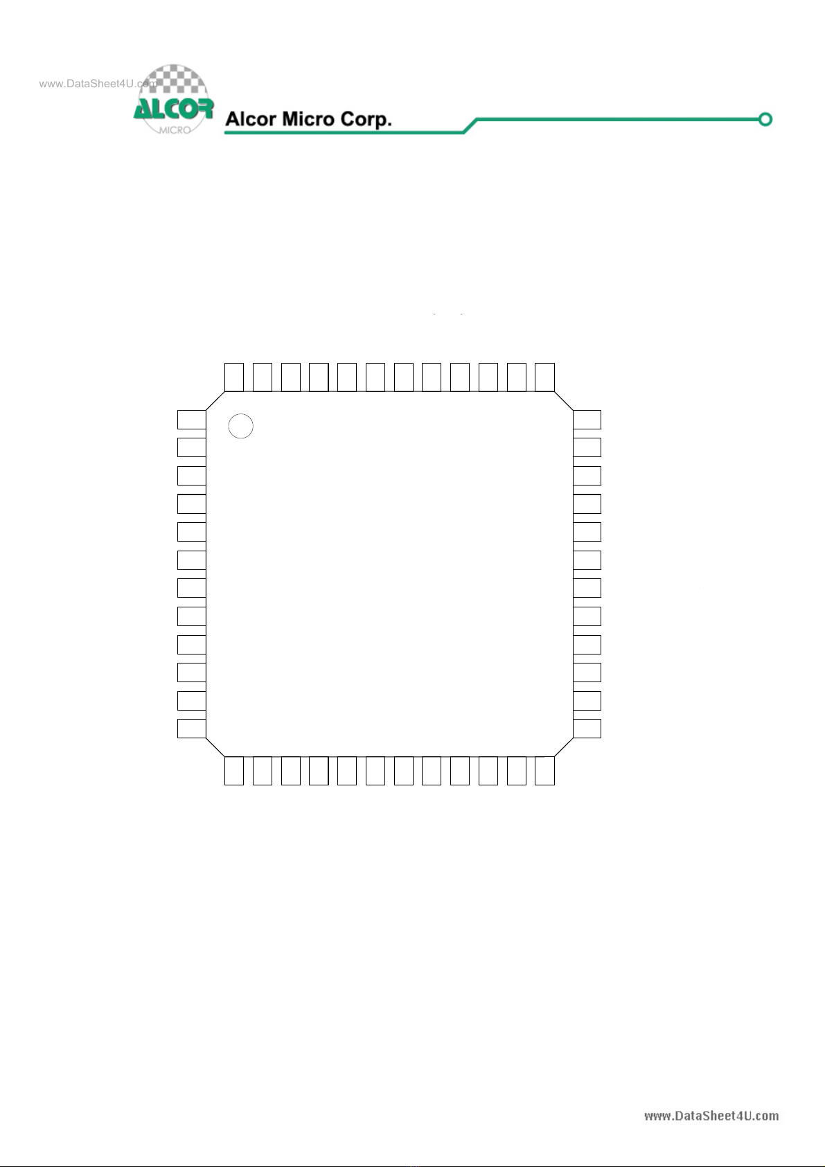
Table 3.1 Pin Descriptions
Pin No. Pin Name I/O Type Description
1 AVCC PWR
Provides 3.3V analog input power to silicon;
Connects to BVCC;
2 AVSS PWR Ground Pin of AVCC Power Plane
3 XTAL1 I 12 MHz Crystal Input
4 XTAL2 O 12 MHz Crystal Output
5 VCC5V PWR 5V Input Power from USB port
6 BVCC PWR
Provides 3.3V analog output power from
internal regulator
7 BVSS PWR Ground Pin of BVCC Power Plane
8 SWITCHN I Push Button for switching to next system (0:
Enable; 1: Normal)
9 AUDIOSWITCHN I Audio On/Off Switch (1: Off; 0: On)
10 BUS_PWRD I Bus power selection (1: Device Self Power; 0:
Bus Power)
11 BEEP O Audio Output (4KHz frequency) when system
switches
12 DP4_PWRUP O Power Up For DownPort4
13 DOWNUSB4_DP I/O DownPort4 DP
14 DOWNUSB4_DM I/O DownPort4 DM
15 SYS1BUTTONN I System1 Enable (0: Enable ; 1: Normal)
16 SYS2BUTTONN I System2 Enable (0: Enable ; 1: Normal)
17 DP2_PWRUP O Power Up for DownPort2
18 DP1_PWRUP O Power Up for DownPort1
19 DOWNUSB2_DP I/O DownPort2 DP
20 DOWNUSB2_DM I/O DownPort2 DM
21 DOWNUSB1_DP I/O DownPort1 DP
22 DOWNUSB1_DM I/O DownPort1 DM
23 Virtual_KBD_Port1 I Control Virtual Keyboard Port1 (0: Enable; 1:
Disable)
24 VSS PWR Ground Pin for VCC Power Plane
25 VCC PWR 3.3 V Input Power; Connects to BVCC
26 SWITCHMODE0 I
27 SWITCHMODE1 I
Switch Mode Selection: (SW0, SW1)
(0,0): [Scroll][Scroll] Mode
(0,1): [CapsLock][CapsLock] Mode
(1,0): [NumLock][NumLock] Mode
(1,1): [CTRL][SHIFT] Mode (Left Hand Side)
28 Virtual_KBD_Port2 I Control Virtual Keyboard Port2 (0: Enable; 1:
Disable)
29 PS2_CLK/No
Connection I PS2 Clock Output; No Connection if only
support USB Keyboard
30 PS2_DAT/No
Connection I PS2 Data Output; No Connection if only support
USB Keyboard
31 Reserved Connect to ground; Reserved for system use
32 Reserved Connect to ground; Reserved for system use
www.DataSheet4U.com

Page 10 of 21
AU9223 USB KVM Controller V1.00
Official Release_ Public
Pin No. Pin Name I/O Type Description
33 Reserved Reserved for system use. Please see reference
circuit schematics for suggested connection
34 GPO2 O General Purpose Output Pin2
35 GPO1 O General Purpose Output Pin1
36 GPO0 O General Purpose Output Pin0
37 MONITOR1EN O Monitor 1 Enable (0: Enable; 1: Disable)
38 MONITOR2EN O Monitor 2 Enable (0: Enable; 1: Disable)
39 Reserved Connect to ground; Reserved for system use
40 Port2Detect I Connect to Upstream Port 2's VCC
41 Port1Detect I Connect to Upstream Port 1's VCC
42 UPUSB1_DP I/O Upstream Port 1 DP
43 UPUSB1_DM I/O Upstream Port 1 DM
44 UPUSB2_DP I/O Upstream Port 2 DP
45 UPUSB2_DM I/O Upstream Port 2 DM
46 UP1LEDN O System 1 LED Indicator
47 UP2LEDN O System 2 LED Indicator
48 NC No Connection Required
www.DataSheet4U.com

Page 11 of 21
AU9223 USB KVM Controller V1.00
Official Release_ Public
4.0 System Architecture and
Reference Design
4.1 AU9223 Block Diagram
Figure 4.1 AU9223 Block Diagram
USB Protocol
Engine USB
Protocol Engine
Downstrea
m
Port Data
Check
Downstream
Port Control
Downstream
Port Control
Downstream
Port
Data Mux
Port 4
Port 4
Port 1
,
2
,
3
Host 1 Host 2
Switch
Detection
www.DataSheet4U.com

Page 12 of 21
AU9223 USB KVM Controller V1.00
Official Release_ Public
5.0 Hot Key Definition
AU9223 supports 4 level of “Hot Key” mode to help users to switch PC, rapidly and
easily, via hot key sequence defined using keypads on the left hand side of a
keyboard.
5.1 [Scroll]++[Scroll] mode
Hot Key Definition
[Scroll] ++ [Scroll] + 1(note1) Switch to PC1
[Scroll] ++ [Scroll] + 2 Switch to PC2
[Scroll] ++ [Scroll] + →or ↓Switch to Next PC
[Scroll] ++ [Scroll] + ←or ↑Switch to Previous PC
[Scroll] ++ [Scroll] + B Beeper On/Off (note2)
[Scroll] ++ [Scroll] + S Auto-scan mode every 10 second. (“ESC” switch to
regular key code.)
[Scroll] ++ [Scroll] + S + n Set Auto-scan rate (note3).
(“ESC” switch to regular key code)
[Scroll]++[Scroll]+F1~F8 Customer define key (note4).
[Scroll]++[Scroll]+[Caps] Switch to [Caps]++[Caps] hot key mode
[Scroll]++[Scroll]+[Num] Switch to [Num]++[Num] hot key mode
[Scroll]++[Scroll]+[Ctrl] Switch to [Ctrl]+[Shift] hot key mode
5.2 [Caps]++[Caps] mode
Hot Key Definition
[Caps]++[Caps]+1 Switch to PC1
[Caps]++[Caps]+2 Switch to PC2
[Caps]++[Caps]+→or ↓Switch to Next PC
[Caps]++[Caps]+←or ↑Switch to Previous PC
[Caps]++[Caps]+B Beeper On/Off (note2)
[Caps]++[Caps]+S Auto-scan mode every 10 second.
[Caps]++[Caps]+S + n Set Auto-scan rate (note3)
[Caps]++[Caps]+F1~F8 Customer define key (note4)
[Caps]++[Caps]+[Scroll] Switch to [Scroll]++[Scroll] hot key mode
[Caps]++[Caps]+[Num] Switch to [Num]++[Num] hot key mode
[Caps]++[Caps]+[Ctrl] Switch to [Ctrl]+[Shift] hot key mode
www.DataSheet4U.com

Page 13 of 21
AU9223 USB KVM Controller V1.00
Official Release_ Public
5.3 [Num]++[Num] Mode
Hot Key Definition
[Num]++[Num]+1 Switch to PC1
[Num]++[Num]+2 Switch to PC2
[Num]++[Num]+→or ↓Switch to Next PC
[Num]++[Num]+←or ↑Switch to Previous PC
[Num]++[Num]+B Beeper On/Off (note2)
[Num]++[Num]+S Auto-scan mode every 10 second. (“ESC” switch to
regular key code.)
[Num]++[Num]+S + n Set Auto-scan rate (note3)
(“ESC” switch to regular key code)
[Num]++[Num]+F1~F8 Customer define key (note4)
[Num]++[Num]+[Scroll] Switch to [Scroll]++[Scroll] hot key mode
[Num]++[Num]+[Caps] Switch to [Caps]++[Caps] hot key mode
[Num]++[Num]+[Ctrl] Switch to [Ctrl]+[Shift] hot key mode
5.4 [Ctrl]+[Shift] mode
Hot Key Definition
[Ctrl]++[Ctrl] Switch to next live PC
[Ctrl + Shift + 1] Switch to PC1
[Ctrl + Shift + 2] Switch to PC2
[Ctrl + Shift + →or ↓] Switch to Next PC
[Ctrl + Shift + ←or ↑] Switch to Previous PC
[Ctrl + Shift + B] Beeper On/Off (note2)
[Ctrl + Shift + S] Auto-scan mode every 10 second. (“ESC” switch to
regular key code.)
[Ctrl + Shift + S + n] Set Auto-scan rate (note3)
(“ESC” switch to regular key code)
[Ctrl + Shift + F1~F8] Customer define key (note4)
[Ctrl + Shift + Scroll] Switch to [Scroll]++[Scroll] hot key mode
[Ctrl + Shift + Caps] Switch to [Caps]++[Caps] hot key mode
[Ctrl + Shift + Num] Switch to [Num]++[Num] hot key mode
www.DataSheet4U.com

Page 14 of 21
AU9223 USB KVM Controller V1.00
Official Release_ Public
Note 1: “++” means press key rapidly, “[Scroll]++[Scroll]+1” means press “Scroll”
twice rapidly and then press “1”. If system receives “Scroll ++ Scroll” command only,
system will reset the buffer when it does not receive any input comes after within a
defined interval of time (say, 5 seconds).
Note 2: Audible feedback when beeper is ON and keep the device in silent mode
when beeper is OFF.
Note 3: n = number from 1 to 9, each represents 5 seconds’ interval latency to 60
seconds correspondingly.
Auto-scan rate set
【N】number Second
1 5
2 10
3 15
4 20
5 25
6 30
7 35
8 40
9 60
www.DataSheet4U.com

Page 15 of 21
AU9223 USB KVM Controller V1.00
Official Release_ Public
Note 4:
GPO 2 GPO 1 GPO 0
Function key +F1 0 0 0
Function key +F2 0 0 1
Function key +F3 0 1 0
Function key +F4 0 1 1
Function key +F5 1 0 0
Function key +F6 1 0 1
Function key +F7 1 1 0
Function key +F8 1 1 1
www.DataSheet4U.com

Page 16 of 21
AU9223 USB KVM Controller V1.00
Official Release_ Public
6.0 Electrical Characteristics
6.1 Recommended Operating Conditions
Table 6.1 Recommended Operating Conditions
SYMBOL PARAMETER MIN TYP MAX UNITS
VCC Power Supply 4.75 5 5.25 V
VIN Input Voltage 0 VCC V
TOPR Operating Temperature 0 85 OC
TSTG Storage Temperature -40 125 OC
6.2 General DC Characteristics
Table 6.2 General DC Characteristics
SYMBOL
PARAMETER CONDITIONS MIN TYP MAX UNITS
IIL Input low current no pull-up or pull-down -1 1 µA
IIH Input high current no pull-up or pull-down -1 1 µA
IOZ Tri-state leakage current -10 10 µA
CIN Input capacitance 5 ρF
COUT Output capacitance 5 ρF
CBID Bi-directional buffer capacitance 5 ρF
6.3 DC Electrical Characteristics for 3.3 volts operation
Table 6.3 DC Electrical Characteristics for 3.3 volts operation
SYMBOL PARAMETER CONDITIONS MIN TYP MAX UNITS
VIL Input Low Voltage CMOS 0.9 V
VIH Input Hight Voltage CMOS 2.3 V
VOL Output low voltage IOL=4mA, 16mA 0.4 V
VOH Output high voltage IOH=4mA,16mA 2.4 V
RIInput Pull-up/down
resistance Vil=0V or
Vih=VCC 10k/200k
KΩ
www.DataSheet4U.com

Page 17 of 21
AU9223 USB KVM Controller V1.00
Official Release_ Public
6.4 Crystal Oscillator Circuit Setup for
Characterization
The following setup was used to measure the open loop voltage gain for crystal
oscillator circuits. The feedback resistor serves to bias the circuit at its quiescent
operating point and the AC coupling capacitor, Cs, is much larger than C1 and C2.
Figure 6.1 Crystal Oscillator Circuit Setup for Characterization
6.5 ESD Test Results
Test Description : ESD Testing was performed on a Zapmaster system using the
Human-Body –Model (HBM) and Machine-Model (MM), according to MIL_STD 883
and EIAJ IC_121 respectively.
Human-Body-Model stress devices by sudden application of a high
voltage supplied by a 100 PF capacitor through 1.5 Kohm resistance.
Machine-Model stresses devices by sudden application of a high voltage
supplied by a 200 PF capacitor through very low (0 ohm) resistance
Test circuit & condition
Zap Interval : 1 second
Number of Zaps : 3 positive and 3 negative at room temperature
Critera : I-V Curve Tracing
Table 6.4 ESD Data
Model Model S/S TARGET Results
HBM Vdd, Vss, I/C 15 4000V Pass
MM Vdd, Vss, I/C 15 200V Pass
www.DataSheet4U.com

Page 18 of 21
AU9223 USB KVM Controller V1.00
Official Release_ Public
6.6 Latch-Up Test Results
Test Description: Latch-Up testing was performed at room ambient using an
IMCS-4600 system which applies a stepped voltage to one pin per device with all
other pins open except Vdd and Vss which were biased to 5 Volts and ground
respectively.
Testing was started at 5.0 V (Positive) or 0 V(Negative), and the DUT was biased for
0.5 seconds.
If neither the PUT current supply nor the device current supply reached the
predefined limit (DUT=0 mA , Icc=100 mA), then the voltage was increased by 0.1
Volts and the pin was tested again.
This procedure was recommended by the JEDEC JC-40.2 CMOS Logic
standardization committee.
Notes:
1. DUT: Device Under Test.
2. PUT: Pin Under Test.
Figure 6.2 Latch-Up Test Results
Pin
under
test
+
Vcc
DUT
GND
m
Untested
Output Open
Circuit
Untested
Input Tied
to V supply
Trigger
Source
V Supply
+
Icc Measurement
1 Source
Test Circuit : Positive Input/ output Overvoltage /Overcurrent
Pin
under
test
www.DataSheet4U.com

Page 19 of 21
AU9223 USB KVM Controller V1.00
Official Release_ Public
Vcc
DUT
GND
Pin
under
test
mA
Untested
Output Open
Circuit
Untested
Input Tied
to V supply
Trigger
Source
V Supply
+
+
Icc Measurement
1 Source
Test Circuit: Negative Input/Output Overvoltage/Overcurrent
Vcc
DUT
GND
mA
Untested
Output Open
Circuit
All Input Tied
to V supply
V Supply
+
Icc Measurement
Supply voltage Test
Table 6.5 Latch–Up Data
Model Model Voltage (v)/ Current (mA) S/S Results
+
Voltage - 11.0
11.0 5 Pass
+
Current - 200
200 5
Vdd-Vxx 9.0 5 Pass
www.DataSheet4U.com

Page 20 of 21
AU9223 USB KVM Controller V1.00
Official Release_ Public
7.0 Mechanical Information
The Following diagram shows the dimensions of the AU9223 48-pin LQFP.
Measurements are in inches.
Figure 7.1 Mechanical Information Diagram
www.DataSheet4U.com
Table of contents
Other Alcor Matrix Switcher manuals