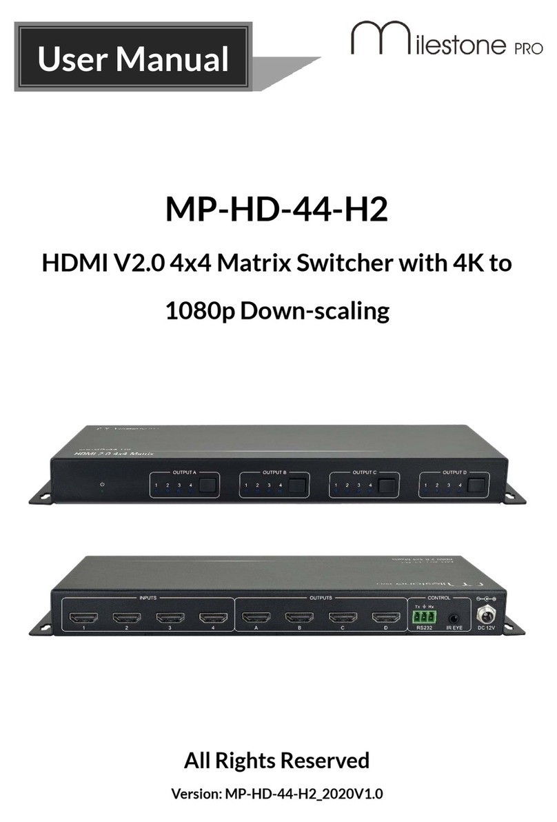
Milestone pro MP-MUH2-42T User manual

MP-MUH2-42T
4x2 Matrix Switcher
All Rights Reserved
Version:MP-MUH2-42T_2020V1.0
User Manual

4x2 Matrix Switcher
Table of Contents
1. Product Introduction....................................................................................................1
1.1 Features ............................................................................................................1
1.2 Package List......................................................................................................1
2. Specification ...............................................................................................................2
3. Panel Description........................................................................................................4
3.1 Front Panel........................................................................................................4
3.2 Rear Panel.........................................................................................................5
4. System Connection.....................................................................................................6
5. Button Control.............................................................................................................7
5.1 Manual Switching ..............................................................................................7
5.2 Auto Switching...................................................................................................7
6. GUI Control.................................................................................................................8
6.1 Video Tab............................................................................................................................9
6.2 Audio Tab..........................................................................................................................10
6.3 Configuration Tab............................................................................................................11
6.3.1 PoC Setting ...........................................................................................11
6.3.2 EDID Setting..........................................................................................12
6.4 CEC Tab............................................................................................................................13
6.5 Tags Tab............................................................................................................................15
6.6 RS232 Tab........................................................................................................................16
6.7 Network Tab.....................................................................................................................18
6.8 Security Tab......................................................................................................................19
6.9 GUI Upgrade ...................................................................................................20
7. IR Remote Control....................................................................................................21
8. RS232 Control..........................................................................................................22
8.1 RS232 Control Connection..............................................................................22
8.1.1 Control the Matrix Switcher....................................................................22
8.1.2 RS232 Pass-through Between Matrix Switcher and Transmitter...........23
8.1.3 RS232 Pass-through Between Matrix Switcher and Receiver...............25
8.1.4 RS232 Pass-through Between Transmitter and Receiver .....................26

4x2 Matrix Switcher
8.2 RS232 Commands..........................................................................................27
8.2.1 System Setting ......................................................................................27
8.2.2 Signal Switching....................................................................................30
8.2.3 Audio Setting .........................................................................................31
8.2.4 HDCP and EDID Setting........................................................................32
8.2.5 Third-party Device Control.....................................................................34
9. Firmware Upgrade....................................................................................................38

4x2 Matrix Switcher
1
1. Product Introduction
Thank you for your purchase of the professional 4x2 matrix switcher! The switcher is a
four-input by two-output matrix switcher with two HDBaseT inputs, two HDMI inputs and
two HDBaseT + HDMI outputs. The switcher transmits 4K video to distances up to 131
feet (40 meters) and 1080p video to distances up to 230 feet (70 meters) over a single
CATx cable. The HDBaseT inputs and outputs support 48V Power over Cable (PoC)
feature, allowing the compatible transmitters and receivers to draw their power from the
matrix over the CATx cable.
The matrix supports downscaling so a 4K video input can automatically be down scaled
to a 1080p output when connecting a display that only supports resolution up to 1080p.
Moreover, the matrix switcher features comprehensive EDID management and
advanced HDCP handing to ensure maximum functionality with a wide range of video
sources. The switcher offers IR, RS232 and TCP/IP control options.
1.1
Features
⚫4x2 matrix switcher with HDBaseT inputs and outputs.
⚫Fully compliant with the HDMI V2.0 and HDCP 2.2.
⚫Supports video resolution up to 4K@60Hz 4:4:4, HDR10, Dolby Vision.
⚫Supports auto-switching.
⚫Features two mirrored HDMI outputs for two HDBaseT outputs, and all outputs
support 4K to 1080p down-scaling.
⚫HDBaseT inputs and outputs support 48V PoC, allowing the transmitters and
receivers to draw their power from the matrix switcher over CATxcables.
⚫Visually lossless video de-compression and compression for HDMI signals
transmission up to 40m at 4K and 70m at 1080p on HDBaseT inputs andoutputs.
⚫Supports Stereo + SPDIF audio outputs for audio de-embedding.
⚫Controllable via front panel buttons, RS232, IR and TCP/IP (built-inGUI).
1.2
Package List
⚫1x MP-MUH2-42T 4x2 matrixswitcher
⚫2x Mounting Ears with 4 Screws
⚫4x Plastic Cushions
⚫1x RS232 Cable (3-pin to DB9)
⚫1x IR Receiver
⚫1x IR Remote
⚫1x Power Adaptor (24V DC5A)
⚫1x User Manual
Note: Please contact your distributor immediately if any damage or defect in the
components is found.

4x2 Matrix Switcher
2
2. Specification
Video Input
Input
(2) HDBaseT, (2) HDMI
Input Connector
(2) RJ45, (2) Type-A female HDMI
HDMI Input Resolution
Up to 4K@60Hz 4:4:4, HDR10, Dolby Vision
HDBaseT Input Resolution
Up to 4K@60Hz 4:2:0
Video Output
Output
(2) HDBaseT, (2) HDMI
Output Connector
(2) RJ45, (2) Type-A female HDMI
HDMI Output Resolution
Up to 4K@60Hz 4:4:4, HDR10, Dolby Vision
Supports 4K to 1080p down-scaling.
HDBaseT Output Resolution
Up to 4K@60Hz 4:2:0.
Supports 4K to 1080p down-scaling.
HDMI Audio Signal
LPCM 7.1 audio, Dolby Atmos®, Dolby® TrueHD, Dolby Digital®
Plus, DTS:X™, and DTS-HD® Master Audio™ pass-through.
Audio Output
Output
(1) Stereo analog audio, (1) SPDIF audio
Output Connector
(1) 3.5mm jack, (1) Toslink connector
Analog L+R Audio Format
PCM 2CH
Digital SPDIF Audio Format
PCM, Dolby Digital, DTS, DTS-HD
Max Output Level
Stereo: 2.0Vrms ±0.5dB. 2V = 16dB headroom above -10dBV
(316mV) nominal consumer line level signal.
SPDIF: ±0.05dBFS
Frequency Response
20Hz to 20kHz, ±1dB
THD+N
< 0.05%, 20Hz to 20kHz bandwidth, 1kHz sine at 0dBFS level (or
max level)
SNR
Stereo: >80dB, 20Hz to 20kHzbandwidth
SPDIF: > 90dB, 20Hz to 20kHzbandwidth
Crosstalk Isolation
Stereo: < -80dB, 10kHz sine at 0dBFS level (or max level before
clipping)
SPDIF: < -70dB, 10KHz sine at 0dBFS level (or max level before
clipping).
L-R Level Deviation
Stereo: < 0.05dB, 1kHz sine at 0dBFS level (or max level before
clipping)
Output Load Capability
Stereo: 1KΩ and higher (Supports 10x paralleled 10KΩ loads).
Noise Level
Stereo: -80dB.
SPDIF: -90dB

4x2 Matrix Switcher
3
Control Part
Control port
(1) FW, (1) RS232, (1) IR EYE, (1) TCP/IP
Control Connector
(1) Micro-USB, (1) 3-pin terminal block, (1) 3.5mm jack, (1) RJ45
General
HDMI Version
2.0
HDCP Version
2.2
Transmission Mode
HDBaseT
Transmission Distance
1080p ≤230 feet (70 meters),
4K@60Hz ≤131 feet (40 meters)
Bandwidth
18Gbps
Operation Temperature
-5 to +55℃(+23°to +131°F)
Storage Temperature
-25 to +70℃(-13°to +158°F)
Relative Humidity
10% to 90%, Non-condensing
External Power Supply
Input: 100 to 240V AC, 50/60Hz; Output: 24V DC 5A
Power Consumption
45W (Max)
Dimension (W*H*D)
300mm x 25mm x 220mm
Net Weight
1.6kg

4x2 Matrix Switcher
4
3. Panel Description
3.1
Front Panel
①Power LED: Illuminates solid red when the device is powered on.
②Out A:
⚫
Auto LED: Illuminates green in auto switching mode.
⚫
1-4: Four input LEDs, one of which illuminates green to indicate which source
is selected for output A.
⚫
Select/Auto/3s: Press the button repeatedly to cycle through the four video
inputs. Press and hold the button for 3 seconds to enter or exit auto switching
mode.
③Out B:
⚫
Auto LED: Illuminates green in auto switching mode.
⚫
1-4: Four input LEDs, one of which illuminates green to indicate which source
is selected for output B.
⚫
Select/Auto/3s: Press the button repeatedly to cycle through the four video
inputs. Press and hold the button for 3 seconds to enter or exit auto switching
mode.
④Audio Out:
⚫
A/B LED: Two audio source LEDs, one of which illuminates green to indicate
which audio source is selected for stereo and SPDIF audiooutputs.
⚫
Select: Press the button repeatedly to cycle through the two audio sources for
audio de-embedding.
⑤FW: Micro-USB port for firmware upgrade.
Out A
Out B
Audio Out
Auto/3s
Auto/3s
Auto 1 2 3 4 Select
Auto 1 2 3 4
Select
A B Select
FW
1
2
3
4
5

4x2 Matrix Switcher
5
3.2
Rear Panel
①Inputs:
⚫
1~2: Connects to compatible HDBaseT transmitters.
⚫
3~4: Connects to HDMI source devices.
②Outputs:
⚫
HDBaseT Outputs: Connects to compatible HDBaseTreceivers.
⚫
HDMI Outputs: Connects to HDMI display devices.
③Audio Out: Connects to audio player for audio de-embedding from HDBT output A
or B.
④RS232: Connects to a control device (e.g. PC) or a third-party device for RS232
control. Please refer to 8. RS232 Control for more details.
⑤IR EYE: Connects to IR receiver to control the switcher by the IR remote. Please
refer to 7. IR Remote Control for more details.
⑥TCP/IP: Connects to the control device (e.g. PC) to control the switcher by Web
GUI. Please refer to 6. GUI Control for more details.
⑦DC 24V: DC connector for the power adapter connection.
Tx Rx
1
2
3
4
A
B
Outputs
Audio Out
RS232 IR EYE TCP/IP DC 24V
1
2
3
4 5 6 7

4x2 Matrix Switcher
6
4. System Connection
The following diagram illustrates typical input and output connections that can be
utilized with this matrix switcher:
Laptop 4K TV
HDCP
LIN K
HDCP LIN K
Tx R x
Tx R x
Transmitter
Receiver
Amplifier
IR Receiver Laptop
Receiver
Transmitter
Remote
Laptop
4K TV
HDMI:
Audio:
HDBaseT:
RS232:
Ethernet:
IR Control:
OUT A
AUTO 1
2
3
4
AUTO 1
2
3
4
AUDIO
AB

4x2 Matrix Switcher
7
5. Button Control
5.1
Manual Switching
When the switcher is in manual switching mode, the Auto button LED goes out. Please
follow the below steps to switch input source to output channel.
1) Press Select button at Out A block to select input source for HDBaseT + HDMI
output A, and the corresponding source LED turns green.
2) Press Select button at Out B block to select input source for HDBaseT + HDMI
output B, and the corresponding source LED turns green.
5.2
Auto Switching
Press and hold Select button at least 3 seconds at Out A block to enable auto
switching mode for output A, and then the Auto LED will turngreen.
Press and hold Select button at least 3 seconds at Out B block to enable auto
switching mode for output B, and then the Auto LED will turn green.
When in auto switching mode, the switcher will switch according to the following rules:
⚫The switcher will switch to the first available active input starting at input 1 to 4.
⚫New input: The switcher will automatically select the new input once detecting a
new input.
⚫Reboot: If power is restored to the switcher, it will automatically reconnect the input
before powered off.
⚫Source removed: When an active source is removed, the switcher will switch to the
first available active input starting at HDMI input 1.
⚫Detection method: TMDS or 5V (The default is 5V and it can be selected by RS232
commands).
⚫The current input source can be switched by Select button on front panel, IR
remote and RS232 commands, and the switcher doesn’t exit the auto switching
mode.
Note: In auto switching mode, press and hold the Select button at least 3 seconds to
enable manual switching mode, but the input source will not be switched.

4x2 Matrix Switcher
8
6. GUI Control
The switcher can also be controlled via TCP/IP. The default IP settings are:
IP Address:
192.168.0.178
Subnet Mask:
255.255.255.0
Type 192.168.0.178 in the internet browser, it will enter the below log-in webpage:
Username: admin
Password: admin
Type the user name and password, and then click Login to enter the section for video
switching.

4x2 Matrix Switcher
9
6.1
Video Tab
⚫HDBT OUT A: Select input source 1~4 for outputA. Click Auto to enable auto
switching mode for output A.
⚫HDBT OUT B: Select input source 1~4 for output B. Click Auto to enable auto
switching mode for output B.
Use the 6 numbered buttons under preset area to save and load layout presets.
•To save a given layout, first click one of the
numbered buttons, then click the Save
button.
•To load a previously saved layout, first click
one of the numbered buttons, then click the
Recall button.

4x2 Matrix Switcher
10
6.2
Audio Tab
•Select HDBT OUT A de-embedded audio, HDBT OUT B de-embedded audio for
SPDIF + Stereo audio outputs.

4x2 Matrix Switcher
11
6.3
Configuration Tab
6.3.1 PoC Setting
•Turn on/off PoC for HDBT input 1~2 and HDBT output A~B.

4x2 Matrix Switcher
12
6.3.2 EDID Setting
•Select a compatible built-in EDID for the selected input source, and then click
Confirm to save setting.
•Upload user-defined EDID by the below steps:
1) Prepare the EDID file (.bin) on the control PC.
2) Select the User-defined.
3) Click the box , and then select the EDID file (.bin) according the
tooltip.
4) Click Apply to upload the user-defined EDID.
5) If invoke the user-defined EDID, select it and then click Confirm.

4x2 Matrix Switcher
13
6.4
CEC Tab
If the input source devices, output devices support CEC, they can be controlled via the
following CEC interface.
1) Source Device Control
⚫Select one or several input source devices to be controlled, and then press function
buttons.
2) Display Device Control

4x2 Matrix Switcher
14
⚫Select one or several output devices to be controlled, and then press function
buttons.
Note: The CEC standard is mainly formulated by TV manufacturers, and is mainly
compatible with its TVs and Blu-ray Players, and may not be compatible with the
source devices of other manufacturers, such as various set top boxes, Apple TV, etc.
3) User-defined Control
The switcher also provides user-defined CEC functions, the CEC command can be
edited and saved in the Trigger box.
⚫Select the input source, and then type CEC command in the Trigger 1 or Trigger 2
box to control the selected source.
⚫Select the output display, and then type CEC command in the Trigger 1 or Trigger 2
box to control the selected display.

4x2 Matrix Switcher
15
6.5
Tags Tab
⚫INPUTS: Modify the label of input sources.
⚫Preset: Modify the label of presets.

4x2 Matrix Switcher
16
6.6
RS232 Tab
1) RS232 Mode
Select the RS232 mode in this tab.
⚫Local Control: The RS232 port of the switcher is used to connect control device
(e.g. PC) to control the switcher.
⚫HDBT Transmitter Pass Through: Establish RS232 pass-through communication
between the switcher and the HDBaseT transmitter.
⚫HDBT Receiver Pass Through: Establish RS232 pass-through communication
between the switcher and the HDBaseT receiver.
⚫Pass Through Between Transmitter and Receiver: Establish RS232 pass-
through communication between the HDBaseT transmitter and HDBaseT receiver.

4x2 Matrix Switcher
17
2) RS232 Mode
⚫Select command sending port.
✓Local: Send RS232 commands to control the local third-party which is
connected to the RS232 port of the switcher.
✓HDBT In 1: Send RS232 commands to control the far-end third-party which is
connected to the RS232 port of HDBaseT transmitter. The transmitter is
connected to the HDBT input 1 port.
✓HDBT In 2: Send RS232 commands to control the far-end third-party which is
connected to the RS232 port of HDBaseT transmitter. The transmitter is
connected to the HDBT input 2 port.
✓HDBT Out 1: Send RS232 commands to control the far-end third-party (e.g.
projector) which is connected to the RS232 port of HDBaseT receiver. The
receiver is connected to the HDBT output 1 port.
✓HDBT Out 2: Send RS232 commands to control the far-end third-party (e.g.
projector) which is connected to the RS232 port of HDBaseT receiver. The
receiver is connected to the HDBT output 2 port.
⚫Set command format to HEX or ASCII.
⚫Baud Rate: Supports 2400, 4800, 9600, 19200, 38400, 57600 or 115200.
⚫Command Ending: NULL, CR, LF or CR+LF can be chosen.
⚫Command: Typecommand in this textbox, and then click Send to control the third-
Table of contents
Other Milestone pro Matrix Switcher manuals
Popular Matrix Switcher manuals by other brands
Extron electronics
Extron electronics FOX Matrix 3200 user guide
American Dynamics
American Dynamics AD2052 Installation and operating instructions
Kramer
Kramer VS-1616A user manual

Kindermann
Kindermann 7488 000 229 user manual

Kramer
Kramer VP-8x8 user manual
Extron electronics
Extron electronics MVX 128 VGA A Specification sheet
