Alde Compact 3010 User manual

GB
Service Manual
Compact 3010

3
The central heating system uses two or three heat sources
– an LPG boiler and a 230 volt electrical heating cartridge,
as well as an externally-tted heat exchanger for motor
caravans. The LPG boiler/heating cartridge heats up a
liquid mixture consisting of water (60%) and glycol (40%).
With the aid of a 12-volt circulation pump, which is located
in an expansion vessel, the warm glycol/water mixture is
circulated round the system through pipes and convectors.
Page Chap Designation
3 1:0 About the Alde central heating system
4 1:1 Maintaining the heating system
4 2:0 About the Compact 3010
4 2:1 How the heater works
5 2:2 The LPG boiler
5 2:3 Technical data
6 3:0 Replacing components
6 3:1 Replacing the printed circuit board
6 3:2 Replacing fan
7 3:3 Replacing a burner
The convectors, which are tted along the outer walls,
heat up the air, which rises and warms the walls and
furniture. As the warm air rises, it forms an air-barrier
which prevents cold from the windows entering.
The temperature inside the caravan is controlled by
a 12-volt thermostat on the control panel.
1:0 ABOUT THE ALDE CENTRAL HEATING
SYSTEM
CONTENTS
Page Chap Designation
7 3:4 Replacing spark electrode
7 3:5 Replacing ame sensor
8 3:6 Replacing solenoid valve
8 3:7 Replacing sensor
9 4:0 Fault messages in the panel
9 5:0 Safety checks
10 6:0 Exploded diagram
11 6:1 Article numbers on exploded diagram
12 7:0 Electrical diagram with control panel
13 8:0 Spare parts
LPG boiler
Compact 3010
Convector
Heat exchanger 2968
Hose and roof ue
Roof vent
Window
Air intake
Convectors

4
1:1 MAINTAINING THE HEATING SYSTEM
Check the heating system’s uid level regularly in the expan-
sion vessel. The level should be approximately 1cm above the
Min mark when the system is cold. The heating system should
be lled with a mixture of water and glycol. For preference, use
high quality pre-mixed glycol (with inhibitor) intended for use in
aluminium heating systems.
If using concentrated glycol, the mixture should consist of 60%
water and 40% glycol. If the heating system will be exposed
to temperatures below –25°C, the glycol content must be
increased, but not to more than 50%.
Any vessels used in handling the liquid must be spotlessly
clean, and the pipes in the heating system must be free of
contamination. This will prevent the growth of bacteria in the
system. The glycol mixture should be changed every second
year, since its ability to protect against corrosion, for example,
will deteriorate. The glycol content should be checked before
topping up with new liquid. This will ensure that the concentra-
tion of glycol in the mixture is not too high.
If the uid level in the expansion tank falls for reasons other
than evaporation, check all joints, drain cocks and bleeder
screws to ensure that they are not leaking. If the glycol-water
mixture leaks out, rinse with water and wipe up.
Never allow the heating system to stand empty of glycol uid.
Adding liquid:
Ensure that the vehicle is standing level, and check that the
bleeder screws and drain cocks are closed. Release the plastic
nut on the circulation pump, located on the expansion vessel,
and lift out the pump. Pour the glycol mixture slowly into the
expansion vessel, using a watering can. When the system is
being lled, air pockets may form, depending on how the pipe-
system has been installed. A good indication that there is air
in the system is when the heat only travels a few metres along
the pipe from the boiler, despite the fact that the circulation
pump is operating.
To make relling and bleeding easier, we recommend using
the Alde lling pump which quickly both lls and bleeds the
system automatically.
Bleeding a caravan heating system (manually):
The LPG boiler must be switched on and the circulation pump
switched off. Start by opening the bleeder screws (please refer
to the vehicle instruction book for their location). Leave them
open until liquid escapes through the spout at the air screw.
Switch on the circulation pump and let it run for a while. Check
whether the pipes and radiators all around the caravan are
warm.
If air still remains in the system, try the following:
The LPG must be switched on and the circulation pump
switched off. Lower the front of the caravan as far as possible
using the jockey wheel. Leave it in this position for several
minutes, to allow any air to rise to the highest point in the
system. Open the bleeder screw at the highest point and keep
it open until all the air has escaped.
Then raise the front of the caravan as high as possible using
the jockey wheel, and repeat the process.
Return the caravan to a horizontal position and start the
circulation pump.
Check that the heat is circulating all around the caravan. When
bleeding a trailer or a motor caravan, it is easier to park on a
steep slope, or raise the vehicle using a jack.
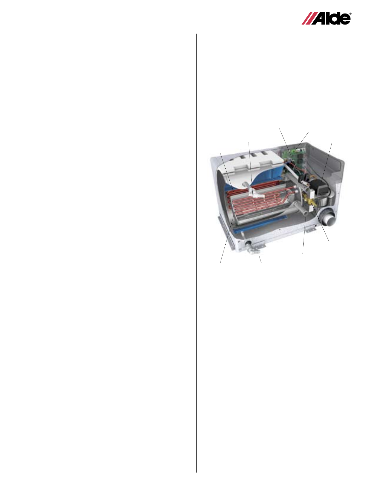
2:0 ABOUT THE COMPACT 3010
The set-up of the boiler.
The boiler consists of three eccentrically-tted pipes. The
innermost pipe is a heat exchanger made from extruded alu-
minium. This is surrounded by a water jacket containing a 40%
glycol mixture which is the uid for the heating system.
The fresh-water heater is located outside the water jacket. The
two outer pipes, as well as their ends and connections, are
made from stainless steel.
The heat exchanger is divided into two semicircular parts by a
u-shaped bafe plate.
The burner is located in the upper semicircle, the combustion
chamber. The bafe plate leads the ue gases back into the
lower part of the section, which constitutes the convection part.
The burner housing is tted on the end of the heat exchan-
ger. On the burner housing is a fan, burner, solenoid valve
and intake/exhaust connections. The exhaust gases escape
through the inner tube, and fresh air enters through the outer
tube. The exhaust fumes exit the vehicle via a hose and ue
tted either to the roof or to the wall. Fresh air enters via the
same ue (balanced draft).
2 electrical heating cartridges are tted to the upper part of the
water jacket. The maximum output of the cartridges is either
2kW or 3kW depending on boiler model.
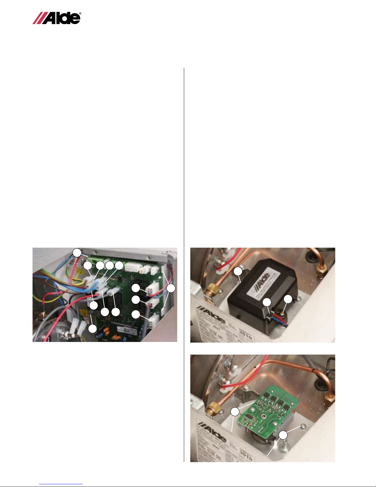
2:1 HOW THE BOILER WORKS
The boiler is a combined unit for producing heat and hot water.
Electricity, LPG or a combination of both are used as energy
source. The electrical elements, of which there are two, have
an output of 1kW and 2kW respectively. The output is control-
led via a relay on a printed circuit board, and depending on
the model of the card, the maximum output is 2kW or 3kW
respectively. When starting, not all the power is connected in
at the same time, but connecting-in goes in two or three steps
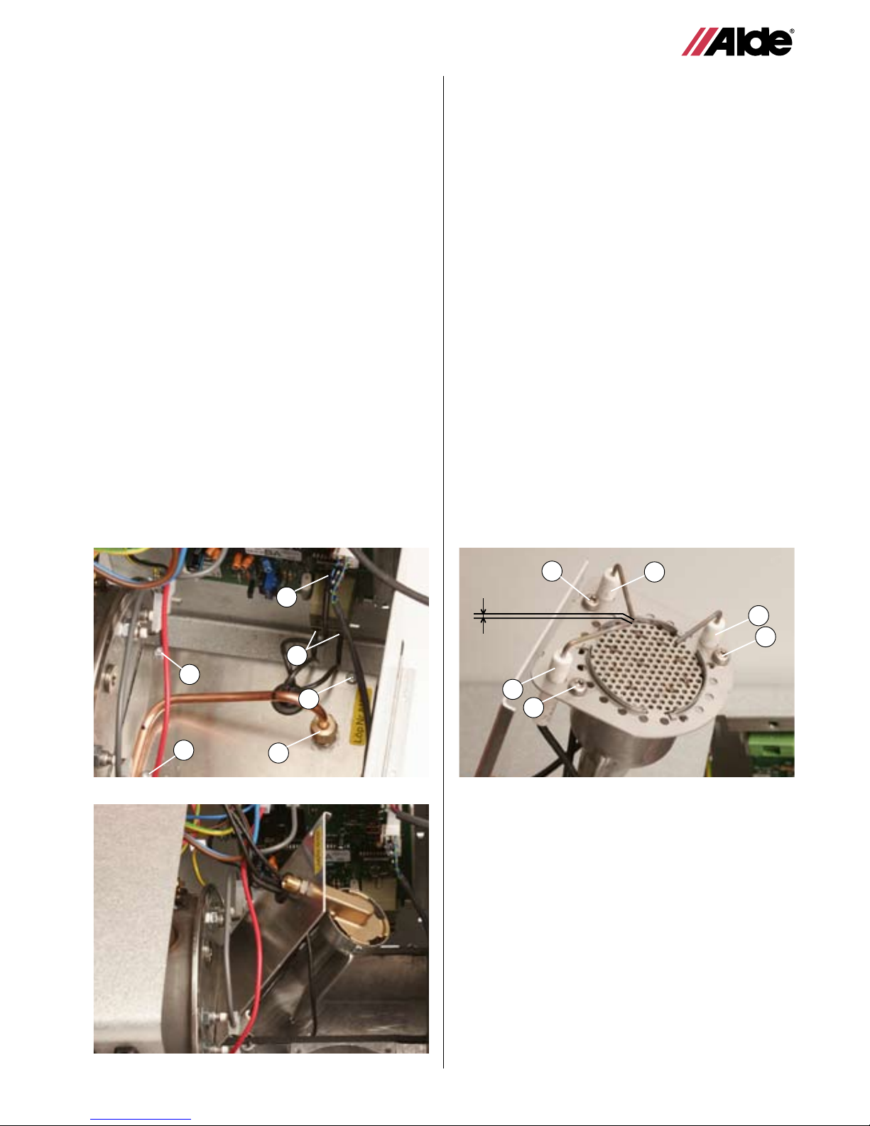
with a few seconds delay between them. The LPG heater has
a burner that works in two steps. The lower of the two steps is
3kW, and the higher is 5.5kW. The power step that the heater
works on is determined by the requirement for heat in the
vehicle. Functions are also connected to the printed circuit
board that are required for monitoring and controlling the
heater.
They can be divided into the following units:
• Monitoring and regulating the speed of the fan at the two
different power steps.
• Opening the different power steps of the gas valve at the
right point of time. The ignition sparks the burner via the two
spark electrodes mounted on the burner.
• Monitoring of the ame through ionised sensing via ame
sensor pin mounted on the burner.
• Control and monitoring of radiator temperature via sensor
mounted on the boiler body.
Control of warm water temperature via sensor mounted on
the heater.
• Regulation of room temperature in the vehicle via sensors
in the panel or sensors connected to the panel.
Filling pump
Art no 1900 811

5
2:3 TECHNICAL DATA
Measurements: Height Width Length
Boiler size: 305 mm 340 mm 490 mm
Rec. Min. installation
dimensions. 310 mm 400 mm 500 mm
Weight: 14 kg (without liquid)
Gas: Propane Butane
Output step 1: 3,3 kW 3.8 kW
Consumption: 245 g/h 275 g/h
Output step 2: 5,5 kW 6,4 kW
Consumption: 405 g/h 460 g/h
Gas pressure I3+ 28-30/37 mbar
I3B/P 30 mbar
Liquid volume/Pressure
Liquid volume, glycol mix: 3,5 liter
Liquid volume, fresh water: 8,4 liter
Max pressure, heating system: 0,05 MPa (0,5 bar)
Max pressure, fresh water: 0,3 MPa (3,0 bar)
System temperature: max 85°C.
230 V ~
Output element : 1 x 1050 W
(2 or alternatively 3 kW) 1 x 2100 W
12 V DC
Current consumption: 1 amp (max)
Fuse: 3,15 amp+/3,15 amp-
2:2 THE LPG BOILER
Starting
When the gas heater receives the signal to start, the system
commences with an auto-check period in which the fan starts
up at constant voltage and works at a speed of about 3000 rpm.
If the speed is within the tolerance at the end of the period, a
spark is generated, the solenoid valve opens the rst step for
gas, and the speed of the fan reduces to 2150 rpm. When the
burner ignites, the electronics receive a signal via the sensor,
the ignition ceases and the burner burns at step 1 for at least
one minute before going over to the second power step if the
need for heat so requires.
If the burner does not ignite within 10 seconds after the gas
valve has opened, the attempt to start is discontinued and a
new cycle commenced. If this also does not succeed, no further
attempts to start will be made, and the text “GAS OUT” will be
shown in the panel. In order to reset the boiler, gas must be
shut off on the panel and switched on again.
Operation
When the burner is working, the ame is monitored via the
ame sensor pin. If the ame goes out, the signal from the
sensor is broken and the gas supply is shut off within 1 second.
After that, the heater attempts to start in accordance with the
description given above.
The burner fan speed is also continuously monitored when in
operation. At step 1, the fan speed is 2150 ±250 rpm and at
step 2 it is 3200±250 rpm. If the fan speed goes down to less
than 2950 rpm, the heater changes down to step 1, and if the
fans speed slows again so that it is below the permitted speed,
the heater is completely switched off and the text “FAN” is
shown in the display. In order to reset, it is necessary for the
main current to the boiler to be broken and then switched on
again.
Changing between power steps
The heater always ignites at step 1. In changing from step 1 to
step 2, the fan speed increases from 2150 to 3200 rpm over in
2.5 seconds. When the fan speed exceeds 2600 rpm, the gas
valve opens for step 2, while step 1 is kept open all the time.
In order to open the gas valve’s step, the electronics send 12
volts to each respective coil’s opening circuit for 1 to 2 seconds.
After this, the valve is kept open using the holding circuit. The
opening circuit has a current consumption of about 1.5A, while
the holding circuit’s current consumption is only about 0.05A.
Regulation
The temperature in the vehicle is regulated with respect to the
difference between the actual temperature within the vehicle
and the required temperature set in the panel (Δt).
If electricity of 3kW + gas has been selected, the heater regula-
tes as follows:
Δt Function
+0.7°C Pump 33 % El. 1 kW
+0.5°C Pump 66 % El. 2 kW
+0.0°C Pump 100% El. 3 kW
-0.5°C Pump 100% El. 3 kW Gas step 1 33%
-1.0°C Pump 100% El. 3 kW Gas step 1 66%
-1.5°C Pump 100% El. 3 kW Gas step 1 100%
-2.0°C Pump 100% El. 3 kW Gas step 1 100% step 2 33%
-2.5°C Pump 100% El. 3 kW Gas step 1 100% step 2 100%
If, for example, only gas has been selected in the panel, the
step for electricity goes out and gas step 1 33% comes in at
the top of the regulation.
The maximum radiator temperature when the circulation pump
is running is 82ºC. When the circulation pump stops, the maxi-
mum temperature is 75ºC.
Warm water
The heater continuously keeps warm water at a basic tem-
perature of about 50ºC. If the temperature goes down below
this level, the heater increases power to a level in accordance
with the control steps above. This may mean the temperature
rising somewhat within the vehicle, which in turn means that
the pump stops and the heater goes over to only generating
warm water for a period of time.
If there is no need for heat, but the boiler is only working to
generate warm water, the heater works on the electrical power
selected; if only gas has been selected, the heater works at
gas step 1.
Electrical heating
cartridge 1kW
Burner fan
Solenoid valve
Fresh water
connection IN
Fresh water
connection OUT
Electronics
Electrical heating
cartridge 2kW
Glycol mixture IN
Glycol mixture
OUT

6
3:0 REPLACING COMPONENTS
Always switch off the 12 V DC and 230 V ~ power supply, and turn the main gas cock to the off position before
starting any servicing. The seals (marked in red) must NOT be broken unless special permission has been obtai-
ned from Alde.
Fig 10.
Fig 2.
A
3:1 REPLACING THE PRINTED CIRCUIT
BOARD
1. Remove the service panel on the boiler.
2. Detach the blue cable (marked Blue)(g.1A) and brown cable
(marked Brown)(g.1B), red cable (marked Red)(g. 1C),
grey cable (marked Grey)(g. 1D) and black cable (marked
Black)(g. 1E) on the printed circuit board, and the blue
(marked PUMP-N) (g.1F) and brown (marked PUMP-L)(g.
1G) if the boiler is equipped with a 230V circulation pump.
3. Release the white 6-point connection block (g.1H) from the
sensors on the printed circuit board.
4. Detach the white 4-point connection block (g.1I) from the
fan on the printed circuit board.
5. Detach the white 5-point connection block (g.1J) from the
solenoid valve on the printed circuit board.
6. Untight the hex-screw on the printed circuit board (g. 1K).
7. Remove the printed circuit board by pressing together the
three hooks, (g. 1L), and pulling out the circuit board.
8. Push the new circuit board rmly in and connect the cables
as shown in g. 1.
9. NB! Tighten the hex-screw holding the printed circuit board
(g 1K).
10.Ret the service panel and test-run the electrical heating
cartridge.
NB! Caution! Take preventative measures against static
electricity when handling the printed circuit board.
Static can damage the PCB.
3:2 REPLACING FAN
1. Remove the service panel on the boiler
2. Release the cable from the fan motor by lifting the hook
(g. 2A) and pulling the cable straight out.
3. Release the plastic housing from the motor,
2 screws (g 2B).
4. Release the 4 plate screws (g. 3A) securing the fan
to the fan housing.
5. Lift the fan out of the boiler body.
6. Fit the new fan by following these instructions in reverse.
NB! Take care not to damage the impeller when tting
the fan.
7. Ret the service panel and test-run the boiler.
Fig 1.
B
H
F
E
G
C D
I
J
K
L
L
Fig 3.
B
A
B
A
A
CABLE MARKINGS FIG.1
1A Blue cable, marked Blue on the printed circuit board.
1B Brown cable, marked Brown on the printed circuit board.
1C Red cable, marked Red on the printed circuit board.
1D Grey cable, marked Grey on the printed circuit board.
1E Black cable, marked Black on the printed circuit board.
1F Blue cable from pump marked, PUMP-N on the
printed circuit board.
1G Brown cable from pump marked, PUMP-L on the
printed circuit board
1H White 6-point connection block from the sensors.
1I White 4-point connection block from fan.
1J White 5-point connection block from solenoid.

7
3:4 REPLACING SPARK ELECTRODE
When replacing the spark electrode, also replace the
amesensor.
1. Detach the burner as per instructions in 3:3.
2. Release the screws (g. 6A) and remove the spark
electrode (g. 6B).
3. Fit the new electrode, and secure it. Check that the distance
between the points on the spark electrode is 2.5-3.5mm,
and that this is correctly positioned.
4. Ret the burner according to 3.3, and test-start the boiler.
3:5 REPLACING THE FLAME SENSOR
Whenreplacingtheamesensoralsoreplacethespark
electrode.
1. Detach the burner in accordance with 3:3.
2. Release the screws (g. 6 C) and remove the
ame sensor (g. 6 D).
3. Fit the new ame sensor, ensuring that the tip of the ame
sensor is positioned above the burner in accordance with
g. 6., and secure.
4. Fit the burner in accordance with 3:3 and test-start
the boiler.
3:3 REPLACING A BURNER
1. Remove the service panel on the boiler.
2. Release the fan in accordance with 3:2.
3. Remove the sensor cable (g. 4A) and spark electrode
cables (g. 4B) from the printed circuit board.
4. Using two spanners, unscrew the gas pipe from the burner
(g. 4C) and the solenoid valve (g. 7B).
5. Remove the three screws (g. 4D) on the end plate of the
burner against the burner housing.
6. Pull the end plate with burner straight out of the burner
housing (see g. 5).
7. Fit the new burner following the instructions in the reverse
order.
8. Using two spanners, tighten the nuts on the solenoid valve
and on the burner to 7-9 Nm.
Remember to check that the cones are correctly tted to
the pipe.
NB! Check the system and connections for leaks with leak
detector spray when the boiler is running.
9. Connect ame sensor cables and spark electrode cables to
the printed circuit board.
10. Ret the service panel and test run the boiler.
Fig 4.
Fig 5.
A
B
C
D
D
D
Fig 6.
B
A
A
D
B
2,5-3,5 mm
C

8
3:6 REPLACING THE SOLENOID VALVE
1. Remove the service panel on the boiler.
2. Release the connection block (g. 1J) from the printed
circuit board.
3. Unscrew the gas pipe (using two spanners) from the burner
(g. 7A) and the solenoid valve (g. 7B).
4. Release the 3 screws (g. 8A) from the solenoid valve
attachment.
5. If necessary, the outer coil can be unscrewed in order to
make it easier to remove the solenoid valve.
Unscrew the nut (g. 8B).
Remove the plate over the coil (g. 8C) and lift off the top
coil (g. 9A) from the solenoid valve.
6. Lift up the solenoid valve and ret the new one in reverse
order. Check that the cable to the upper coil ts correctly in
the groove in the plate (g. 9B).
7. Tighten the nuts (using two spanners) to the solenoid valve
(g. 7B) and to the burner (g. 7A), to 7-9Nm.
Do not forget to check that the cones are correctly tted on
the pipe.
Check the system and the connections for leaks with leak
detector spray when the boiler is running.
8. Ret the service panel.
3:7 REPLACING THE SENSOR
1. Remove the service panel on the boiler.
2. Release the 6-point connection block (g. 10A) from
the printed circuit board.
3. Release the connection cables from their groove
(g. 10B) on the printed circuit board attachment.
4. Remove the brass screws from the operating thermostat
(blue cable) (g. 11B) and overheating protection
(red cable) (g. 11A) from the boiler body.
5. Lift the hot water thermostat bracket (grey cable)
(g. 11C) from the boiler body.
6. Remove the sensors together.
7. Ret the sensors in reverse order.
8. Ret the service panel and test run the boiler.
Fig 7.
Fig 8.
Fig 9.
B
A
A
B
C
A
B
Fig 11.
Fig 10.
A
B
B
AB
C

9
5:0 SAFETY CHECKS
Safety checks shall be carried out after each service.
Check:
• That the intake/exhaust gas hoses and roof ue do not leak
and are not damaged.
• That the LPG connections do not leak. Check the system
for leaks.
• That the 230V ~ earth connection is connected.
• That the safety valve on the warm water heater has not
been displaced.
• That the heating system has been lled with glycol mixture
up to the mark on the expansion vessel.
4:0 FAULT MESSAGES IN THE PANEL
NB! Fault messages are only shown when the panel is idle
GAS OUT is reset by the main breaker being switched off
and switched on again.
Otherwise, it is reset through the 12-volt main breaker
being switched off and then being switched on again.
GAS OUT
Caused by:
The heater has attempted to light the boiler repeatedly, without
the electronics receiving the signal from the sensor that moni-
tors the ame.
Probable reasons for the fault:
• No gas supply or insufcient gas supply in the vehicle.
• The electronics do not send a signal to the gas valve.
• The gas valve does not open.
• Impurities in the heater’s gas pipes or nozzle.
• No spark from the electronics.
• The spark electrode has been damaged or is incorrectly
mounted.
• The sensor circuit in the electronics is not working.
• The sensor has been damaged or is incorrectly mounted.
• The exhaust/intake hoses have been damaged or are incor-
rectly mounted.
• Insufcient battery voltage or contact fault in cable.
• Break/short circuit in sensor no. 2 (red cable).
OHEAT 1
Caused by:
The blue sensor on the boiler body has registered a tempera-
ture in excess of 100ºC, or break/short circuit.
Probable reasons for the fault:
• Air in the heating system.
• Insufcient circulation or pump not working.
• The sensor has been damaged.
• The electronics are not monitoring the temperature.
OHEAT 2
Caused by:
The red sensor on the boiler body has registered a tempera-
ture in excess of 100ºC, or break/short circuit.
Probable reasons for the fault:
• See OHEAT 1.
FA
Caused by:
The fan has incorrect speed or is not in contact with the elec-
tronics.
Probable reasons for the fault:
• Fault in the fan.
• Break in the wiring between fan and printed circuit board.
• Monitoring by the printed circuit board not working.
BATT LO
Caused by:
The vehicle’s battery voltage is less than 10.5 volts.
Probable reasons for the fault:
• Battery is low.
• Faulty contact between cable and boiler.
• Heater taking abnormally high current.
• Fault in printed circuit board.
WINDO
Caused by:
Connection no. 4 in the panel’s accessory block is broken.
When this is broken, the heater does not function with LPG.
Usually this function is used to break the LPG heat if a window
is opened that is mounted close to the wall ue. If the function
is not used, a loop shall be mounted on the panel.
Probable reasons for the fault:
• Break in connection between switch and panel.
• Window switch damaged or incorrectly mounted.
• The loop incorrectly mounted or not present.
SERIAL
Caused by:
Communication fault between boiler and panel.
Probable reasons for the fault:
• Break in the cable for data communication between heater
and panel.
• Ignition spark goes to earth and interrupts communication.
• Some other electrical apparatus is interrupting
communication.
OTHER FAULTS THAT ARE NOT INDICATED IN
THE PANEL.
The heater is completely inactive and the panel is
not lit up.
• One of the 12-volt fuses has blown.
• The safety fuse has blown.
No electrical power.
• The 230 volts is not connected, or a fuse has blown.
• One of the 230-volt relays is not working.
• Break/short circuit in sensor no. 2 (red cable)
No heating in the vehicle despite the fact that the panel is
correctly installed.
• One of the circulation pumps is not working.
• Air in the heating system.
Incorrect heat regulation.
• The panel or remote sensor is unsuitably located.
No warm water.
• Problem with hot water thermostat (grey cable).
• PE on the panel in position ON.

10
6:0 EXPLODED DIAGRAM
1
48
27
5
36
7
2
3
6
9
11
10
13
12
14
15
17 18
16
19
21
22
23 20
24 25
26
28
29
31
30
34
34
35
32
33
36
10
11
37 38

11
6:1 ARTICLE NUMBERS ON EXPLODED DIAGRAM (FOR SPARE PARTS, SEE PAGE 13)
1. 3010 149 Service cover
2. 3010 148 Service panel
3. 3010 152 Cover
4. 3010 302 Printed circuit board 2 kW
3010 303 Printed circuit board 3 kW
5. 3010 187 Screw
6. 3010 189 Printed circuit board bracket, left
7. 3010 188 Printed circuit board bracket, right
8. 3010 181 Screw
9. 3010 178 Spacer
10. 3010 163 Nut
11. 3010 164 Cone
12. 3010 304 Solenoid valve
13. 3010 182 Screw
14. 3010 312 Copper pipe
15. 3010 182 Screw
16. 3000 452 Fan compl.
17. 3010 182 Screw
18. 2930 235 Cable entry
19. 3010 166 Nut
20. 3010 135 Plate
21. 3010 133 Spark electrode
22. 3010 186 Nut
23. 3010 181 Screw
24. 3010 134 Flame sensor
25. 3010 122 Burner
26. 3010 301 Burner compl.
27. 3010 150 End, front
28. 3010 141 Electrical heating cartridge, 2kW
29. 3010 136 Gasket
30. 3000 140 Electrical heating cartridge, 1kW
31. 3010 153 Bottom plate
32. 3010 200 Clamping ring
33. 3010 110 Boiler body
34. 3010 158 Insulation
35. 3010 151 End, back
36. 3000 472 Nipple
37. 3010 159 Support for back valve
38. 2762 125 Draught vent
Other parts
3010 305 Sensor set
3010 205 Cable to fan

12
7:0 WIRING DIAGRAM WITH CONTROL PANEL

13
1. 3010 305 Sensor set compl.
2. 3010 306 Spark electrode/Flame sensor
1. 3010 301 Burner compl.
2. 3010 304 Solenoid valve compl.
1. 3000 452 Fan compl.
8:0 SPARE PARTS
1. 3010 302 Printed circuit board, 2kW
2. 3010 303 Printed circuit board, 3kW
1.
2.
1.
2.
Other manuals for Compact 3010
8
Table of contents
Other Alde Heating System manuals
Popular Heating System manuals by other brands

Roberts Gorden
Roberts Gorden AG15ST Installation, operation & service manual

Kospel
Kospel SVS Series manual

Fenix
Fenix MADPSP 30 installation manual

Haier
Haier HACI-RP Series Instructions for installation, use and maintenance manual

PrecisionTemp
PrecisionTemp TWINTEMP JR. Operation description

Master
Master BV 77E Technical data