Manuale di Installazione Uso e Manutenzione - Installation, Use and Maintenance Manual
pag. 5
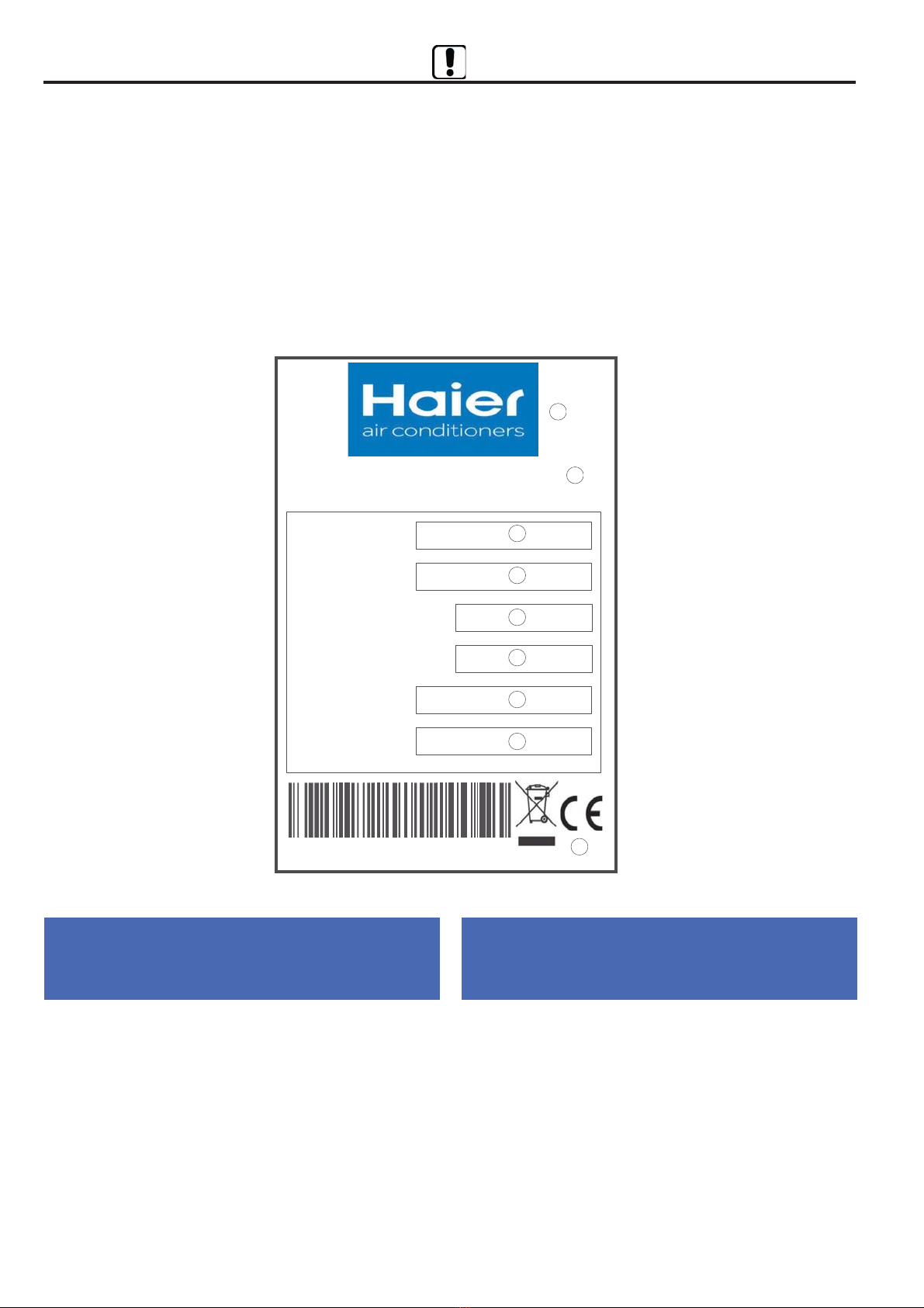
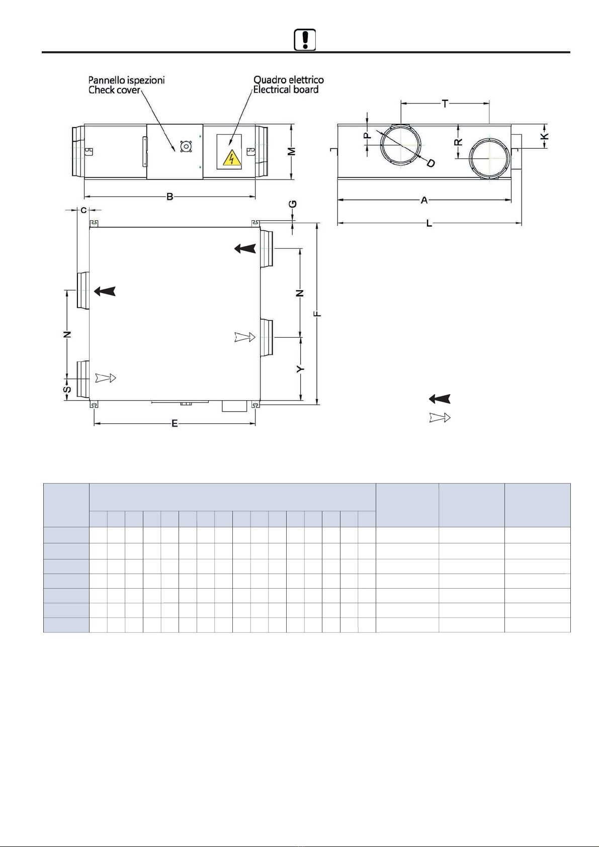
*2.:<*4A%:*-260$8&628.:;76*4.
B2.6-*
758*6A
'2* *:,762 %'
6-2:2BB7
--:.;;
*8
)28,7-.
":7>26,2*
":7>26,.
#.>26.*07 <*4A
<*4A
2<<C
2<A
$<*<7
$<*<.
&62<C-2:.,=8.:7,*47:.
.*<:.,7>.:A=62<
#"
.;,:2B276.
.;,:28<276
$.:2.
$.:2.;
#"57-
7-.442
7-.4;
'.6<24*B276./7:B*<**-78827/4=;;7,76:.,=8.:*<7:.-2,*47:..6<*482,7
;<*<2,7*/4=;;226,:7,2*<2
7=+4./47?5.,1*62,*4>.6<24*<276?2<1.6<1*482,;<*<2,,:7;;/47?
1.*<.@,1*60.:
=6B276.
=6,<276
&62<C-2:.,=8.:7,*47:.;.:2.#"
.*<#.,7>.:A&62<#"
.67526*B276.,755.:,2*4.
755.:,2*46*5.
2:.<<2>* -.4 "*:4*5.6<7 =:78.7 . -.4 76;20427 -.4
5*0027:.4*<2>**44.5*,,126.
2:.<<2>* & -.4 "*:4*5.6<7 =:78.7 . -.4 76;20427 -.4
/.++:*27,76,.:6.6<.24:2*>>2,26*5.6<7-.44.4.02;4*B2762-.042$<*<2
5.5+:2:.4*<2>.*44*,758*<2+242<C.4.<<:75*06.<2,*
2:.<<2>* & -.4 "*:4*5.6<7 =:78.7 . -.4 76;20427 -.4
/.++:*27,76,.:6.6<.24:2*>>2,26*5.6<7-.44.4.02;4*B2762-.042$<*<2
5.5+:2:.4*<2>.*45*<.:2*4..4.<<:2,7-.;<26*<7*-.;;.:.*-78.:*<7
.6<:7<*4=624252<2-2<.6;276.
2:.<<2>* & -.4 "*:4*5.6<7 =:78.7 . -.4 76;20427 -.4
02=067 ;=44* :.;<:2B276. -.44=;7 -2 ;7;<*6B. 8.:2,747;. 6.44.
*88*:.,,12*<=:..4.<<:2,1..-.4.<<:762,1.#7$
2:.<<2>*&-.4"*:4*5.6<7=:78.7.-.476;20427-.44=0427
;=2:2/2=<2-2*88*:.,,12*<=:..4.<<:2,1..-.4.<<:762,1.#
#.074*5.6<7-.44*,7552;;276.&!-2*<<=*B276.-.44*
2:.<<2>* :20=*:-7 *44. ;8.,2/2,1. 8.: 4* 8:70.<<*B276.
.,7,758*<2+24.-.44.=62<C-2>.6<24*B276.
2:.,<2>. 7/ <1. =:78.*6 "*:42*5.6< *6- 7/ <1.
7=6,247/ *A765*,126.:A
2:.,<2>. & 7/ <1. =:78.*6 "*:42*5.6< *6- 7/ <1.
7=6,247/.+:=*:A76<1.*88:7@25*<2767/<1.4*?;7/
<1. .5+.:$<*<.;:.4*<260<7.4.,<:75*06.<2,,758*<2+242<A
2:.,<2>. & 7/ <1. =:78.*6 "*:42*5.6< *6- 7/ <1.
7=6,247/.+:=*:A76<1.1*:5762;*<2767/<1.4*?;7/
.5+.: $<*<.; :.4*<260 <7 .4.,<:2,*4 .9=285.6< -.;206.- /7: =;.
?2<126,.:<*26>74<*0.4252<;
2:.,<2>. & 7/ <1. =:78.*6 "*:42*5.6< *6- 7/ <1.
7=6,247/=6.76<1.:.;<:2,<2767/<1.=;.7/1*B*:-7=;
;=+;<*6,.;26.4.,<:2,*4*6-.4.,<:762,.9=285.6<#7$
2:.,<2>. & 7/ <1. =:78.*6 "*:42*5.6< *6- 7/ <1.
7=6,247/=4A76?*;<..4.,<:2,*4*6-.4.,<:762,.9=285.6<
(
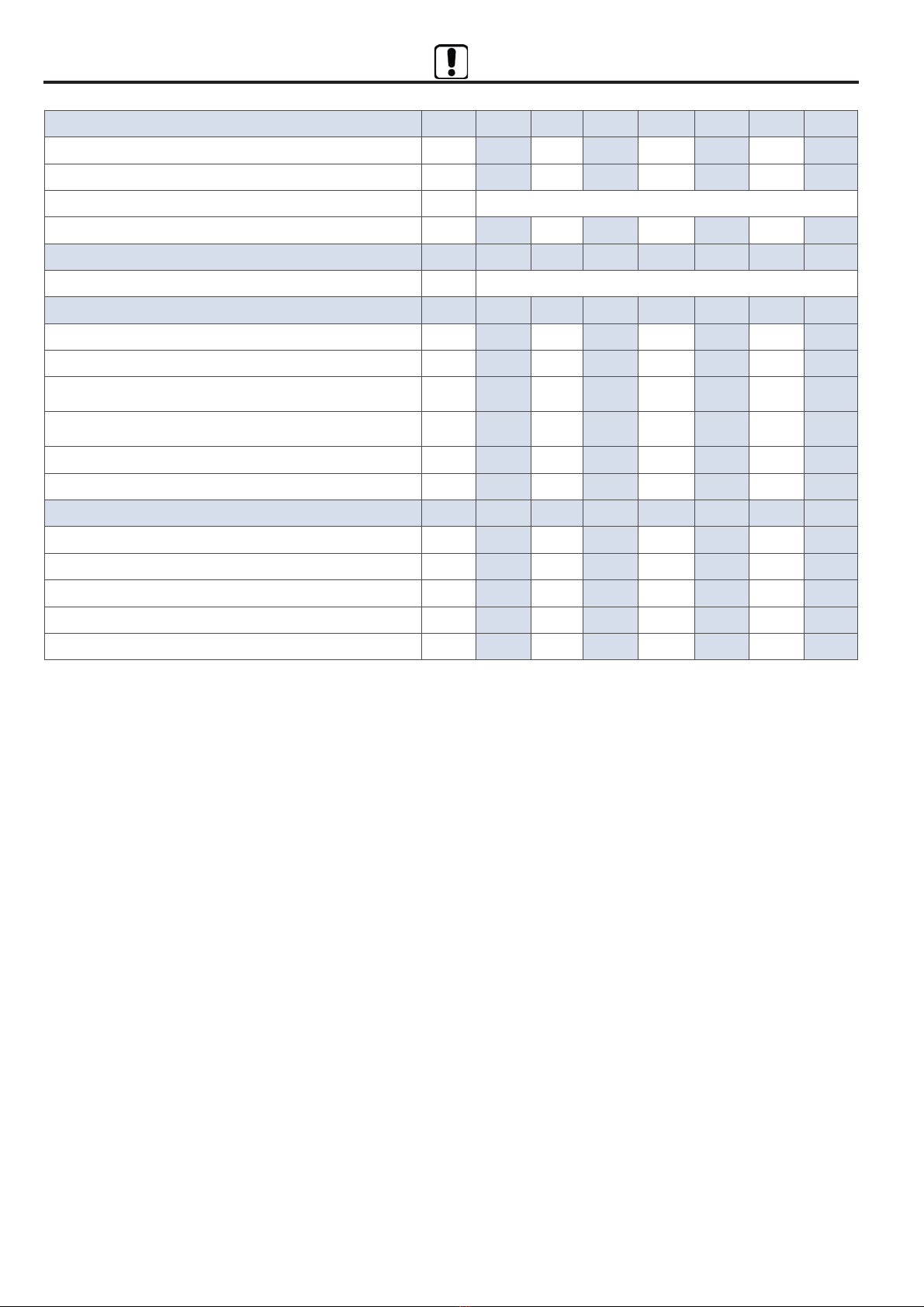
7552;;276 #.0=4*<276 & 2584.5.6<260 2:.,<2>.
:.0*:-260 <1. ;8.,2/2, .,7-.;206 7/ <1. >.6<24*<276
=62<;
*:,75*<<.7$<./*62
!7526*<2>7
!*5.
'2* *:,762 %'
6-2:2BB7
--:.;;
*8
)287-.
":7>26,2*
":7>26,.
#.>26.*07 <*42*
<*4A
2<<C
2<A
$<*<7
$<*<.
*8:.;.6<.8.:-.7062>*42-2<C26,*;7-2=;7258:78:277-2.>.6<=*42
57-2/2,1.-*672676*=<7:2BB*<.*887:<*<.*44.;=--.<<.5*,,126.F
/*<<7 -2>2.<7 -2 5.<<.:. 26 ;.:>2B27 4. =62<C 700.<<7 -2 9=.;<*
-2,12*:*B276. 8:25* ,1. 4* 5*,,126* 7 4E2582*6<7 26 ,=2 ;*:*667
26,7:87:*<. 7 *;;2.5*<. ;2*67 ,76/7:52 *44. -2;87;2B2762 -.44* 2:.<<2>*
*,,126.
6 ,*;. 7/ 258:78.: =;. 7: =6*=<17:2B.- 57-2/2,*<276 7/ <1.
5*,126.:A.9=285.6<<12;-7,=5.6<?244477;.2<;>*42-2<A<2;
/7:+2--.6<78=<<1.=62<<1*<2;7+3.,<7/<12;-.,4*:*<27626;.:>2,.
+./7:.<1.5*,126.7:<1.84*6<26?12,1<1.5*,126.?24478.:*<.
2; 26 ,75842*6,. ?2<1 <1. -2;87;2<276; 7/ *,126.:A 2:.,<2>.
*6-/7447?26057-2/2,*<276;
#.>26.*07!7>.5+:.
#.>26.*07
th November 17
*2.:<*4A%:*-260$8&628.:;76*4.'2* *:,762#.>26.*07%'D<*4A .6<:*4267