18
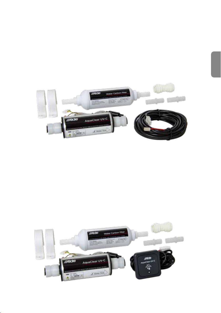
Alde AquaClear 3030033
Installation of Alde AquaClear for Alde 3030/3030 Plus:
1. Switch o the fresh water pump and drain the water pipes to avoid leakage.
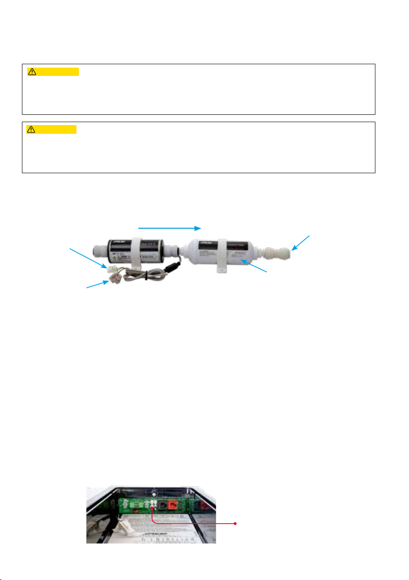
2. Assemble the Alde AquaClear UV-C (g. 1, A) with the Alde Water Carbon lter (g. 1, B).
Please note that Alde Aqua Clear UV-C should be located before the Alde Water Carbon lter in the
ow direction. (See g. 3)
3. Then install the product on the pipe/hose according to the arrow in the direction of water ow,
horizontally or vertically. When placed vertically, the water ow should be able to pump from the
bottom up through Alde AquaClear UV-C to avoid air pockets that impair the ability to clean.
4. Connect the power cable, 12 V-DC, white (+) and brown (-) so that the product receives power when
water is owing, i.e. when the vehicle's fresh water pump is running (gs. 14, 15).
5. The connector with green and yellow wire is connected with the supplied extension cable (g. 1, F). The
cable is then connected to the Ext. Start switch (g. 4) and indicates whether the lter is active on
the control panel during water ow from the water pump.
6. Alde AquaClear UV-C is now ready for use. To activate Alde AquaClear in the control panel, see the
next page.
Ext. Start
g. 4
When testing fresh water in the system of new vehicles in the factory, bypass must be used,
alternatively a pipe bridge instead of Alde AquaClear, to avoid water remaining for a long time and
Alde Water Carbon lter (carbon lter) life is shortened.
g. 3
Flow direction
Connect signal cable to
the boiler circuit board
(See g. 4)
Connection 12 V from the
vehicle's fresh water pump
12 mm JG joint for LLDPE hose.
(When switching to soft hoses, use
the included adapter, 3010678)
Fill in Year and Month for
mounted Alde Water Carbon lter
Units containing water must not be exposed to temperatures below freezing. If there is a risk of frost,
drain the unit. There is a glass pane in front of the product’s UVC source, and the glass is at risk of
breaking if water in the unit freezes.