SPX Hankison SF Series User manual

- 1 -
8590F 41.60.03 KS 41.60.02 DT
emaN-D tlletsre emaN .rpeg emaN .ftztesre .dtztesre
Bedienungsanleitung
Instruction Manual
Hochleistungs - Druckluftfilter
Compressed-air filters
Serie / Series
SF, PF, HF, UF, CF
SPXFlowTechnologyMoersGmbH
Konrad-Zuse-Str. 25
47445Moers
Tel.:02841/819-0
Fax:02841/87112
ab 2014/ EDD
2

- 2 -
8590F 41.60.03 KS 41.60.02 DT
emaN-D tlletsre emaN .rpeg emaN .ftztesre .dtztesre
[1]
MANUFACTURER DECLARATION
[2]
This is to declare that the design and construction of the below mentioned product, in the version
marketed by us, fulfils the relevant basic safety and health requirements of the EC directives listed below.
Any modifications made without prior consultation with us will invalidate this declaration!
[3]
Designation of model: F-02, F-03, F-04, F-06, F-07, F-08, F-10
[4]
Year of construction:
[5]
Classification according to Art. 9of the PED: (Art. 3.3) Modul ------
[6]
Schematic drawing F0742, F0743, F0944
[7]
Application:
[8]
Filter for compressed air
[9]
The above mentioned products are designed and manufactured concerning good sound engineering
practice, which is valid in the member states of the EC.
The SPX Hankison production tests, according to the authorisation regulations, are guaranteed by our DIN
EN ISO 9001-2000 certified quality management system.
[10]
Notes for the user:
[11]
The operator's manual must be referred to for purposes of assembly,
commissioning, operation, maintenance and inspection!
[12]
Manufacturer: SPX Flow Technology
IDA Business and Technology Park,
Tiernaboul, Killarny,
Co. Kerry, Ireland
Killarny
[13]
Location [14] Date

- 3 -
8590F 41.60.03 KS 41.60.02 DT
emaN-D tlletsre emaN .rpeg emaN .ftztesre .dtztesre
[1]
EC DECLARATION OF CONFORMITY
[2]
PRESSURE EQUIPMENT DIRECTIVE 97/23/EC
[3]
This is to declare that the design and construction of the below mentioned products, in the version
marketed by us, fulfil the relevant basic safety and health requirements of the pressure equipment directive.
Any modifications made without prior consultation with us will invalidate this declaration!
[4]
Designation of model: F-11, F-12, F-12, F-13, F-14, F-15, F-16, F-17
[5]
Serial no.:
[6]
Year of construction:
[7]
Pressure equipment:
[7a]
filter housing
[8]
Schematic drawing: F0743, F0747, F0748, F0807, F0944
[9]
Application:
[9a]
Compressed Air Filter
[10]
Classification according to Art. 9of the PED:
[10a]
Category I
[10b]
Module: A
[11]
In accordance with directive 97/23/EC Annex Inumber 3.2, the following tests were performed:
-Pressure test - Test of equipment
-Leak test
-Construction test
[12]
No failures were found.
[13]
EC directives concerned:
[13a]
EC pressure equipment directive (97/23/EC)
[14]
Notes for the user:
[14a]
The operator's manual must be referred to for purposes of assembly,
commissioning, operation, maintenance and inspection!
[15]
Manufacturer: SPX Flow Technology
IDA Business and Technology Park,
Tiernaboul, Killarny,
Co. Kerry, Ireland
Killarny
[16]
Location
[17]
Date
[18]
Signature/ Company executive

- 4 -
8590F 41.60.03 KS 41.60.02 DT
emaN-D tlletsre emaN .rpeg emaN .ftztesre .dtztesre
Inhaltsverzeichnis
1. Einleitung
2. Sicherheitsregeln, Warnhinweise
3. Technische Daten
4. Funktionsbeschreibung
5. Kondensatableiter
6. Transport, Wareneingangskontrolle
7. Montage
8. Inbetriebnahme, Betrieb
9. Wartung
10. Garantiebedingungen
11. Maßzeichnung
12. Demontage und Entsorgung
Wir haben den Inhalt der Bedienungsanleitung auf Übereinstim-
mung mit dem beschriebenen Gerät geprüft.
Dennoch können Abweichungen nicht ausgeschlossen werden,
so dass wir für die vollständige Übereinstimmung keine Gewähr
übernehmen.
Technische Änderungen vorbehalten.
Contents
1. Introduction
2. Safety rules, warnings
3. Technical data
4. Description of functions
5. Condensate drain
6. Transportation, checking of goods
received
7.Assembly
8. Start up, operation
9. Servicing
10. Guarantee conditions
11. Dimensional drawing
12. Disassembly and utilization
We have examined the content of the operating instructions for
conformity with the appliance described.
Inconsistencies cannot be ruled out, however, with the result
that we do not guarantee complete conformity
We reserve the right to alter the specifications without prior
notice
- 5 -
8590F 41.60.03 KS 41.60.02 DT
emaN-D tlletsre emaN .rpeg emaN .ftztesre .dtztesre
1. Einleitung
1.1 Allgemeines
Um den Filter optimal nutzen zu können, benötigt der Anwender
ausführliche Informationen.
In der vorliegenden Betriebsanleitung haben wir diese Informa-
tionen möglichst vollständig und in entsprechende Kapitel geglie-
dert zusammengestellt.
Lesen und beachten Sie diese Informationen.
Sie helfen Ihnen auch Unfälle zu vermeiden.
1.2 Erklärung der Symbole in der
Bedienungsanleitung
Warnhinweise
Warnhinweise gibt es in drei Gefahrenstufen, die Sie an dem
Signalwort erkennen:
•GEFAHR
•WARNUNG
•VORSICHT
Warnhinweise immer sorgfältig lesen und gewissenhaft befol-
gen.
Dieses Zeichen weist auf besonders wichtige
Informationen hin.
1.3 Erklärung der Symbole am Gerät
1. Introduction
1.1 General remarks
In order to obtain maximum benefit from using the filters/ -system
the user should have sufficient information.
These instruction manual gave the user this information which
has been divided into separate sections for easy reference.
Please read carefully before installing and operating the filter/ -
system.
1.2 Explanation to the symbols in the
instruction manual
Warnings
Warning notices indicate three levels of danger signified by the
signal word.
•DANGER
•WARNING
•CAUTION
Always read and comply with warning instructions.
This symbol refers to particularly important information.
1.3 Symbols used in the filter
Druckluft-Eintritt
Air Inlet
trowlangiS
drowlangiS
gnutuedeB
gninaeM
gnuthcaebthciNiebnegloF
ecnavresbo-nonfosecneuqesnoC
RHAFEG
REGNAD
rhafeGrednehordrablettimnurovtnraw
regnadfotaerhttnenimminafosnraW
hcilniehcsrhawdnisgnuztelrevrepröKerewhcsredotoT
tluseryamyrujnisuoiresrohtaeD
GNUNRAW
GNINRAW
rhafeGrednehordrehcilgömrovtnraw
regnadelbissopfosnraW
hcilgömdnisgnuztelrevrepröKerewhcsredotoT
elbissoperayrujnisuoiresrohtaeD
THCISROV
NOITUAC
noitautiSrehcilrhäfegrehcilgömrovtnraw
noitautissuoregnadylbissopafosnraW
hcilgömdnisnedähcshcaSredognuztelrevrepröKethcieL
elbissoperaegamadlairetamroseirujnithgiL

- 6 -
8590F 41.60.03 KS 41.60.02 DT
emaN-D tlletsre emaN .rpeg emaN .ftztesre .dtztesre
2. Sicherheitsregeln,
Warnhinweise
2.1 Bestimmungsgemäßer Gebrauch
Warnung!
•Die Filter dürfen nur für die in dieser Bedienungsanleitung
vorgesehenen Einsatzfälle zur Aufbereitung von Druckluft
verwendetwerden.
•Der einwandfreie und sichere Betrieb der Produkte er-
fordert sachgerechten Transport, Lagerung, Aufstellung
und Montage, sowie sorgfältige Bedienung und Instand-
haltung.
2.2 Sicherheitsregeln
Warnung!
•Die Filter dürfen nur von qualifiziertem Personal genutzt,
bedient, gewartet oder instandgesetzt werden.
•QualifiziertesPersonalimSinnedersicherheitsbezogenen
Hinweise in dieser Dokumentation oder auf dem Produkt
selbst, ist Personal das:
∗imUmgang mit Einrichtungender Druckluft vertrautund un-
terwiesen sowie über die damit verbundenen Gefahren un-
terrichtet ist.
∗Den auf die Bedienung bezogenen Inhalt dieser Doku-
mentation kennt.
∗Es besitzt als solches eine zur Inbetriebnahme und War-
tung derartiger Einrichtungen befähigende Ausbildung
bzw. Berechtigung.
2.3 Warnhinweise
Warnung!
Das (die) Filter ist (sind) ein unter erhöhtem Druck stehen-
des System.
Vor Servicearbeiten sind sie drucklos zu machen.
Lebensgefahr durch elektrische Spannung!
Vor allen Arbeiten an der elektrischen Ausrüstung:
Stromversorgung allpolig abschalten, gegen
Wiedereinschalten sichern undSpannungsfreiheit
prüfen.
Die Filter sind ausschließlich zur Aufbereitung von Druck-
luft einzusetzen.
ACHTUNG!
Die Verwendung in Verbindung mit anderen,
insbesondere brennbaren Gasen ist verboten!
Warnung!
Filter/ -systeme zur Aufbereitung von Atemluft dürfen nur
nach Genehmigung des Herstellers der Filter/ -systeme
eingesetzt und betrieben werden.
2. Safety rules,
warnings
2.1 Use of filter/ -system
Warning!
•The filter must only be used for the purpose as designated
in the instruction manual.
•To obtain maximum efficiency and operation of the filter/ -
systemensure all sections of the manual are read carefully.
2.2 Safety rules
Warning!
•The filter/ -system must only be used, operated, inspected
andrepaired by trained personnel.
•Trained personnel are defined as follows:
∗Operatingstaff who areskilled in thefield of compressedair
engineeringand who arefamiliar with the filter/ -system and
possible dangers in unauthorised operation or service.
∗Who can interpret and action the contents of this operation
instruction manual.
∗Who have had the appropriate training and qualified as
being competent in these fields.
2.3 Security-warnings
Warning!
The filter/ -system contains components under high
pressure.
Before starting any service work turn off compressed air
supply to the filter and depressurise the system.
Danger of fatal injury from electric shock!
Before starting any work on electrical equipment:
Switch off and lock out the power supply
disconnecting device and check thatno voltage is
present.
Use filter for compressed air applications only.
Attention!
The use of other gases (combustible gases) is
prohibited.
Warning!
Filter/ -systems for breathing air applications must be
approved from manufacturer.
- 7 -
8590F 41.60.03 KS 41.60.02 DT
emaN-D tlletsre emaN .rpeg emaN .ftztesre .dtztesre
3. Technische Daten 3. Technical data
Volumenstrom
Capacity Anschluß
Connection
Filter-
Gehäuse/
Housing
Filter-
Grad / Grade [m³/h]
F02-B 34 1/4"
F03-B 59 3/8"
F04-B -SF 85 1/2"
F06-B 127 3/4"
F07-B -PF 175 3/4"
F08-B 267 1"
F10-B -HF 437 1 1/2"
F11-B 612 1 1/2"
F12-B 681 2"
F13-B -UF 993 2 1/2"
F14-B 1317 2 1/2"
F15-B -CF 1750 2 1/2"
F16-B 2039 3"
F17-B 2549 3"
2 3 4 5 6 7 8 9 10 11 12 13 14 15 16
0,38 0,52 0,63 0,75 0,88 1,00 1,13 1,26 1,38 1,52 1,65 1,76 1,87 2 2,14
-14
PF
-12
-13
-16
* Volumenstrom m³/h bezogen auf +20°C und 1 bar abs olut, bei Betriebsdruck 7 barü / Air flow m³/h based on +20°C and 1 bar absolute, at working pressure 7 barg
* Höhere Betriebsdrücke auf Anfrage / Contact factory for filters with a higher working pressure
* ISO 12500
1
1
-15
-11
1
1
-17
1
1
-06
-07
-04
-03
1
1
1
1
16
11
11
UF
CF
11
1
1
-08
-10
1
16
siehe Kapitel "Maßzeichung"
see chapter "Dimensional drawing"
SF
11
11
siehe Kapitel "Maßzeichung"
see chapter "Dimensional drawing"
siehe Kapitel "Maßzeichung"
see chapter "Dimensional drawing"
16
HF
16
-02
16
16
16
16
16
Austausch Filterelemente
Filter replacement cartridge
Filter-
Grad /
Grade
Filter-
Gehäuse/
Housing
Modell Bezeichnung/
Model Designation Betriebsdruck
Working
Pressure
[max]
Abmessungen
Dimensions
Standard
Höhe/
Hight
[mm]
Breite/
Width
[mm]
Anzahl
Quantity
Gewicht
Weight
Standard
[kg]
Volumenstrom - Korrekturtabelle / Sizing
Betriebsbedingungen:
Min Betriebstemperatur: +1°C
Max. Betriebstemperatur: +66°C
Min. Betriebsdruck mit automatischem Kondensatableiter: 2,0 barü
barü/ barg
Minimaler Betriebsdruck / Minimum working pressure
Korrekturfaktor / Correction factor
Working conditions:
Min. working temperature: +1°C
Max. working temperature: +66°C
Min. working pressure with automatic condensate drain: 2,0 barg
Auslegung
Bei Drücken abweichend von 7 barü berechnet sich der Volumenstrom wie folgt:
den Korrekturfaktor des entsprechenden minimalen Betriebsdruckes mit dem gewählten Volumenstrom aus og. Tabelle multiplizieren.
Based on
To find the maximum flow at pressures other than 7 barg:
multiply the flow (from table above) by the correction factor corresponding to the minimum working pressure of the filter.
- 8 -
8590F 41.60.03 KS 41.60.02 DT
emaN-D tlletsre emaN .rpeg emaN .ftztesre .dtztesre
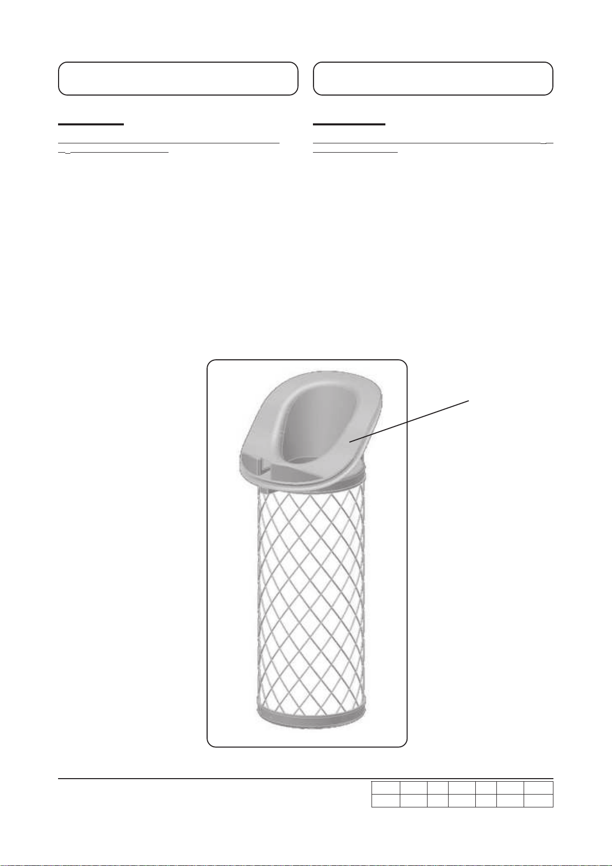
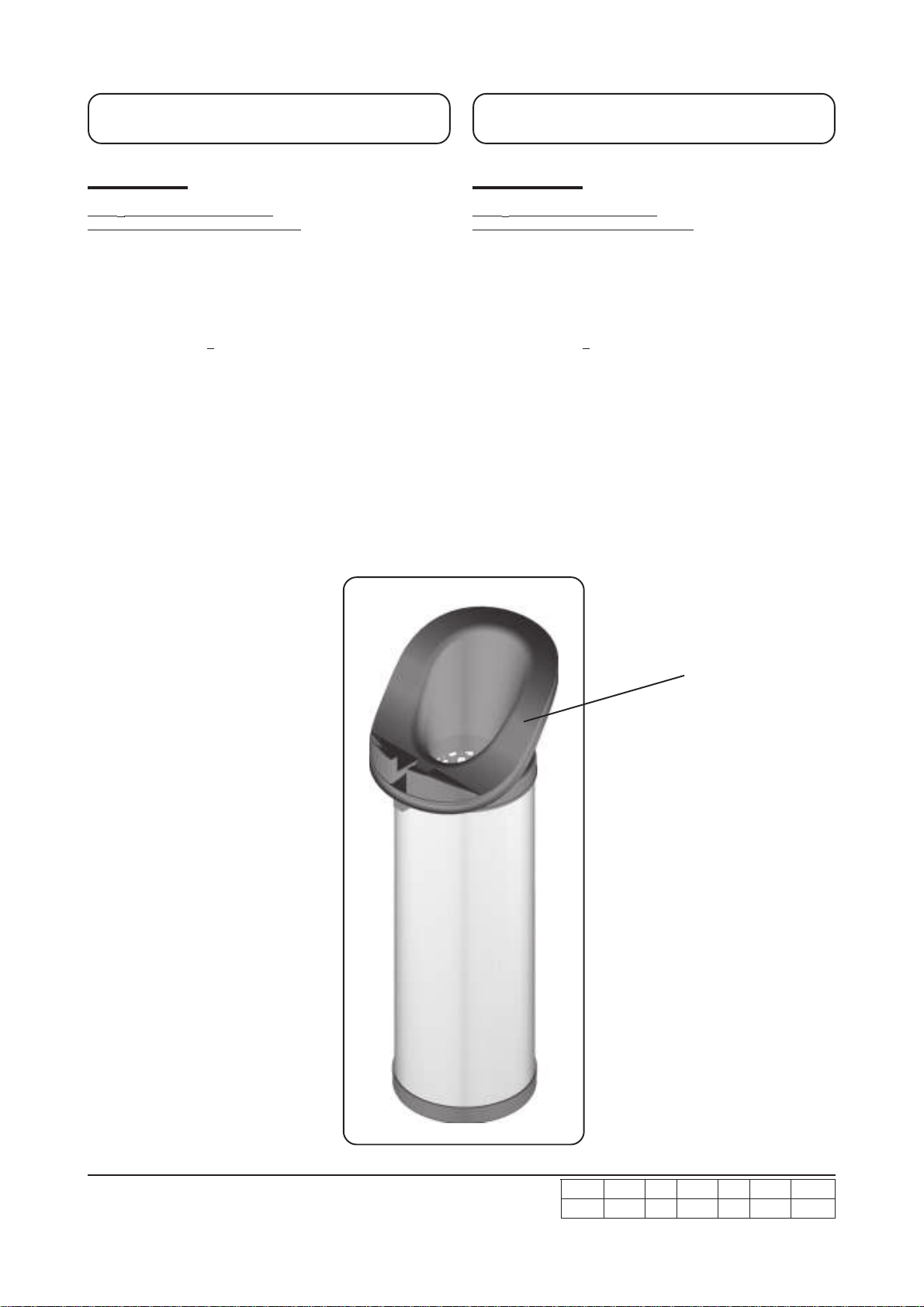
4. Funktionsbeschreibung
4.1 Serie SF
KOMBINATIONAUS MECHANISCHEMABSCHEIDER UND
3-µµ
µµ
µm-COALESCING-FILTER
•Geeignet zum Abscheiden großer Kondensatmengen
•Entfernt mehr als 99% des Kondensats
•Entfernt Feststoffpartikel bis herunter zu 3 µm
•Restölgehalt < 5 ppm w/w
•Automatischer Kondensatableiter
•Differenzdruckanzeige am Filtergehäuse
• max. Flüssigkeitsbeladung: 25 g/m³
Anwendungen:
•Zum Abscheiden von Wasser und Feststoffen für allge-
meine Anwendungen (Werkstattluft, Blasluft)
4. Description of operation
4.1 Series SF
COMBINATION MECHANICAL SEPARATOR AND 3 µµ
µµ
µm
COALESCING FILTER
•Handles large liquid loads
•Removes more than 99% of liquid water
•Removes solid particles down to 3 µm
•Oil content < 5 ppm w/w
•Automatic condensate drain
•Differential pressure indicator at the filter housing
•max. liquid load: 25 g/m³
Application:
•Use as a point-of-use filter where heavy liquid loads are
expected (air systems without aftercoolers or dryers)
orange
orange
- 9 -
8590F 41.60.03 KS 41.60.02 DT
emaN-D tlletsre emaN .rpeg emaN .ftztesre .dtztesre
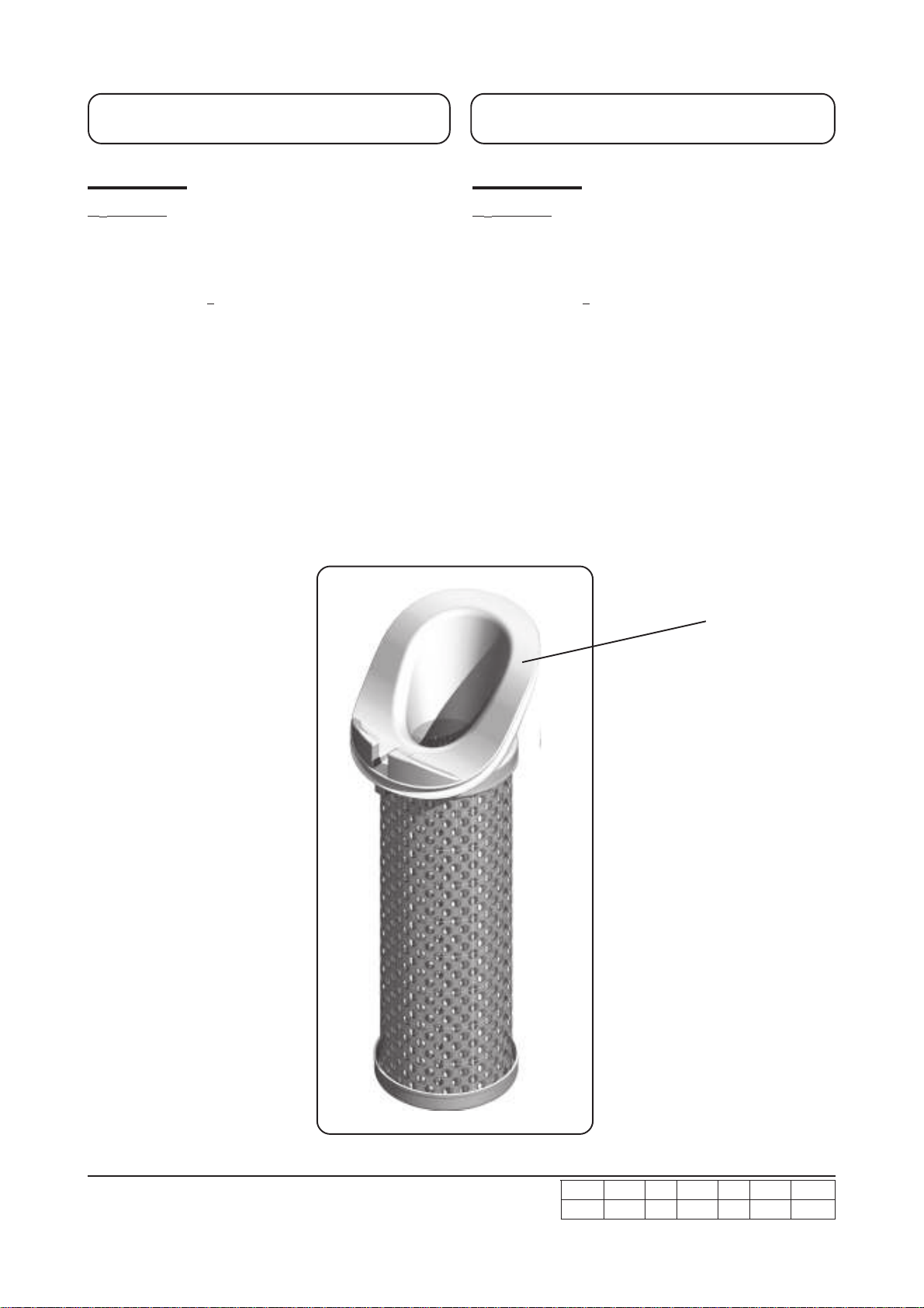
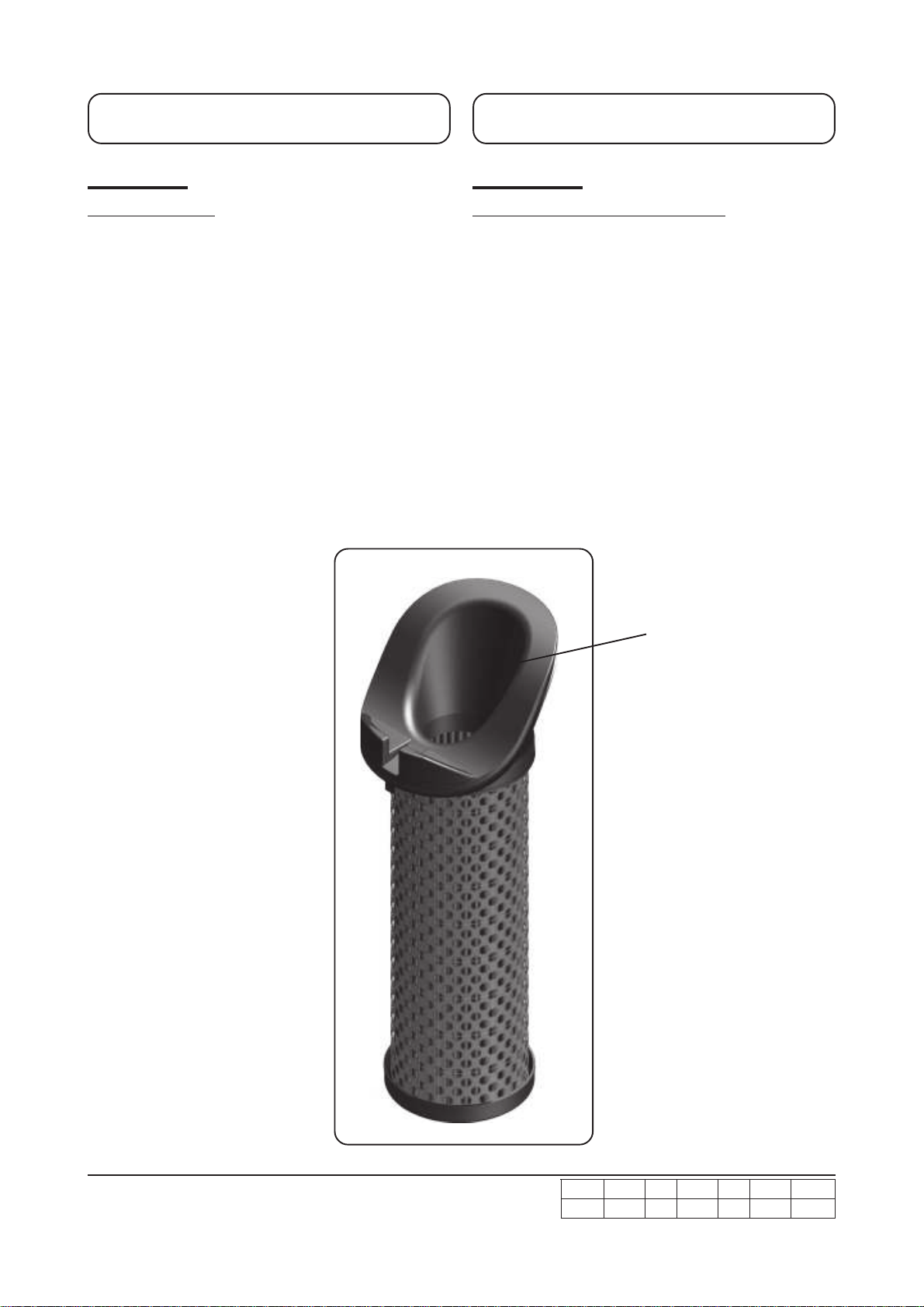
4. Funktionsbeschreibung
4.2 Serie PF
1-µµ
µµ
µm-FILTER
•Zweistufige Tiefenfiltration bewirkt hervorragende Leis-
tung und höhere Standzeiten des Filterelementes
•Entfernt große Mengen des Kondensats
•Entfernt Feststoffpartikel bis herunter zu 1 µm
•Restölgehalt <0,5 ppm w/w
•Automatischer Kondensatableiter
•Differenzdruckanzeige am Filtergehäuse
• max. Flüssigkeitsbeladung: 2 g/m³
Anwendungen:
•Allgemeine Filter für Werkstattluft
•Vorfilter für Hochleistungsfilter
•Nachfilter für Adsorptionstrockner (Staubfilter)
4. Description of operation
4.2 Series PF
1-µµ
µµ
µm-FILTER
•Two in-depth filter beds offer superior performance and
extended cartridge life
•Removes huge amount of liquid water
•Removes solid particles down to 1 µm
•Oil content <0,5 ppm w/w
•Automatic condensate drain
•Differential pressure indicator at the filter housing
•max. liquid load: 2 g/m³
Application:
•General filter for shop air
•Prefilter for high efficiency filters
•Afterfilter for pressure-swing desiccant dryers (Dust
filter)
weiß
white
- 10 -
8590F 41.60.03 KS 41.60.02 DT
emaN-D tlletsre emaN .rpeg emaN .ftztesre .dtztesre
4. Funktionsbeschreibung
4.3 Serie HF
0,01-µµ
µµ
µm-COALESCING-FILTER
(bei 0,01 ppm w/w max. Ölgehalt)
DUO-System Abscheidung
1. Stufe: flüssige Bestandteile
2. Stufe: Ölbestandteile
•Entfernt mehr als 99,99% der Öl-Aerosole
•Entfernt Feststoffpartikel bis herunter zu 0,01 µm
•Restölgehalt <0,01 ppm w/w
•Automatischer Kondensatableiter
•Differenzdruckanzeige am Filtergehäuse
• max. Flüssigkeitsbeladung: 1 g/m³
Anwendungen:
•Vorfilter für Membrantrockner
•Vorfilter für Adsorptionstrockner
•Endstellenfiltration
•Oel-Kondensatfilter
4. Description of operation
4.3 Series HF
0,01-µµ
µµ
µm-COALESCING-FILTER
(at 0,01 ppm w/w max. oil content)
DUO-system separation
1. Stage: liquid particles
2. Stage: oil particles
•Removes more than 99,99% of oil aerosols
•Removes solid particles down to 0,01 µm
•Oil content <0,01 ppm w/w
•Automatic condensate drain
•Differential pressure indicator at the filter housing
•max. liquid load: 1 g/m³
Application:
•Prefilter for membrane dryers
•Prefilter for pressure-swing desiccant dryers
•Point-of-use filter
•Oil coalescing filter
grün
green

- 11 -
8590F 41.60.03 KS 41.60.02 DT
emaN-D tlletsre emaN .rpeg emaN .ftztesre .dtztesre
4. Funktionsbeschreibung
4.4 Serie UF
0,01-µµ
µµ
µm-COALESCING-FILTER
(bei 0,001 ppm w/w max. Ölgehalt)
•Spezial Design garantiert ultrafeine Ölabscheidung für
die gesamte Standzeit des Elementes
•Entfernt mehr als 99,99% der Öl-Aerosole für ölfreie Luft
•Entfernt Feststoffpartikel bis herunter zu 0,01 µm
•Restölgehalt <0,001 ppm w/w
•Automatischer Kondensatableiter
•Differenzdruckanzeige am Filtergehäuse
• max. Flüssigkeitsbeladung: 0,1 g/m³
Anwendungen:
•Pulverbeschichtung
•Blasformverfahren
•Instrumentenluft
•Luftlagerungen
•Pneumatische Förderung
•Elektronik-Anwendungen
•Vorfilter für Membrantrockner (bei größerer Feuchte ist
ein Filter PF als Vorfilter zu installieren)
4. Description of operation
4.4 Series UF
0,01-µµ
µµ
µm-COALESCING-FILTER
(at 0,001 ppm w/w max. oil content)
•Special design guarantee ultra-fine oil separation for the
whole life of the cartrige
•Removes more than 99,99% of oil aerosols for virtually oil
free air
•Removes solid particles down to 0,01 µm
•Oil content <0,001 ppm w/w
•Automatic condensate drain
•Differential pressure indicator at the filter housing
•max. liquid load: 0,1 g/m³
Application:
•Powder coating
•Blow molding
•Pneumatic instrumentation
•Air bearings
•Pneumatic conveying
•Electronics manufacturing
•Prefilter for membrane dryers (use a filter PF as a prefilter
if heavy liquid loads are present)
gelb
yellow
- 12 -
8590F 41.60.03 KS 41.60.02 DT
emaN-D tlletsre emaN .rpeg emaN .ftztesre .dtztesre
4. Funktionsbeschreibung
4.5 Serie CF
AKTIVKOHLE-FILTER
•Zweifache Aktivkohle-Filtration für lange Standzeiten
•Entfernt Öldampf und Geruch- und Geschmacksstoffe,
die von Aktivkohle adsorbiert werden
•Restölgehalt 0,003 ppm w/w
•Dieser Filter entfernt kein Methan, Kohlenmono-
xid, Kohlendioxyd oder sonstige toxische Gase und
Dämpfe
Anwendungen:
•Nahrungsmittel- und pharmazeutische Industrie
•Prozessluft
•Analyseluft
4. Description of operation
4.5 Series CF
ACTIVATED CARBONADSORBENT FILTER
•Two beds of carbon give long live at rated conditions
•Removes oil vapour and other odors and flavors normally
adsorbable by activated carbon
•Oil content 0,003 ppm w/w
••
••
•This filter does not remove methane, carbon
monoxide, carbon dioxide or other toxic gases and
vapors
Applications:
•Food and drug industries where compressed air contacts
products
•Process air
•Analysis air
schwarz
black

- 13 -
8590F 41.60.03 KS 41.60.02 DT
emaN-D tlletsre emaN .rpeg emaN .ftztesre .dtztesre
5. Kondensatableiter
5.1 Kondensatableiter
5. Condensate drain
5.1 Condensate drain
retielbatasnednoK niardetasnednoC
retliF retliF
40-206DDE 01DXS
52092199:.rN 20649049:.rN 01033199:.rN 40503199.rN 50503199:.rN
-retielbatasnednoK ßulhcsna niardetasnednoC noitcennoc
ebuT/hcualhcS elamef/nennimm31 elamef/nenni"8/1R elamef/nenni"2/1R elamef/nenni"2/1R ebuT/hcualhcS elamef/nennimm8 elamef/nenni"4/1R
FS
B-20F
...
B-21F
NOITPO
B-20F ... B-21F
B-31F
...
B-71F
NOITPO
B-31F &B-41F
NOITPO
B-51F ... B-71F
FP
B-20F
...
B-21F
NOITPO
B-20F ... B-21F
NOITPO
B-31F &B-41F
NOITPO
B-51F ... B-71F
B-31F ... B-71F
FH
B-20F
...
B-21F
NOITPO
B-20F ... B-21F
NOITPO
B-31F &B-41F
NOITPO
B-51F ... B-71F
B-31F ... B-71F
FU
B-20F
...
B-21F
NOITPO
B-20F ... B-21F
NOITPOO
B-31F &B-41F
NOITPO
B-51F ... B-71F
B-31F ... B-71F

- 14 -
8590F 41.60.03 KS 41.60.02 DT
emaN-D tlletsre emaN .rpeg emaN .ftztesre .dtztesre
6. Transport,
Wareneingangkontrolle
6.1 Transport
Entsprechend der Bauform und dem Gewicht der Filter/ -systeme
sind geeignete Transportmittel sowie Hebewerkzeuge zu ver-
wenden.
Die Filtergehäuse dürfen auf keinen Fall an den Drucklufteintritts-
und -austrittsstutzen (oder -Flanschen) angehoben werden.
6.2 Wareneingangskontrolle
Die Ware wurde im Herstellerwerk sorgfältig geprüft und im ein-
wandfreien Zustand dem Spediteur übergeben.
Die Dokumentation liegt dem Filter bei.
Überprüfen Sie die Filter/ -systeme auf sichtbare Beschädigun-
gen. Bestehen Sie im Falle einer Beschädigung darauf, dass auf
dem Ablieferungsnachweis des Spediteurs ein entsprechender
Vermerk gemacht wird.
Verständigen Sie unverzüglich den Spediteur und veranlassen
eine Begutachtung.
Für Beschädigungen während des Transportes ist der Herstel-
ler nicht verantwortlich.
6. Transport,
checking of goods received
6.1 Transport
Employ transport and lifting equipment which correspond to the
size and weight of filter and system.
The filter/ -system must by no means be lifted at the compressed
air inlet- or outlet connections.
6.2 Checking of goods received
The filter/ -system is thoroughly checked and packed, before it
leaves the factory. It has been handed over to the forwarding
agent in perfect condition.
All documents are part of the shipment.
Upon receipt please check immediately the filter/ -system for
visible damage. In case of visible damage of the packing, please
insist upon a respective note on the delivery sheet of the
forwarding agent.
Inform the forwarding agent at once and have the filter inspected.
The manufacturer is not responsible for damages occurred
during transport.
- 15 -
8590F 41.60.03 KS 41.60.02 DT
emaN-D tlletsre emaN .rpeg emaN .ftztesre .dtztesre
7. Montage
7.1 Montageort
Das Filter/ -system sollte in einem trockenen, frostfreien Innen-
raum installiert werden.
Zur Wartung ist genügend Freiraum vorzusehen (siehe Kapitel
11)
7.2 Montage
Das Filter/ -system ist senkrecht so zu montieren, daß der
Druckluftein- und austritt waagerecht erfolgt.
Vorsicht!
Achten Sie bei der Montage darauf, daß keine Zug- und
Druckkräfte auf die Geräteanschlüsse übertragen
werden.
7.3 Anschluss an das Druckluftnetz
Die Druckluftein- und -austrittsleitung sollte für Servicezwecke
mit einem Bypass versehen werden.
Die Dimensionierung der Anschlüsse entnehmen Sie bitte dem
Kapitel 3. „Technische Daten“.
Durchflussrichtung beachten.
Druckluftein- und austritt- dürfen nicht vertauscht
werden. Für die korrekte Fließrichtung, beachten
Sie bitte die Pfeile auf dem Filterkopf.
7.4 Kondensatableitung
Für die automatische Kondensatableitung ist bei den Filtern (SF,
HF, PF, UF) ein Anschluss vorhanden.
Die Dimensionierung des Anschlusses entnehmen Sie bitte
Kapitel 5. „Kondensatableiter“.
Achten Sie bei der Montage der Kondensatableitung
darauf, daß das abgeschiedene Kondensat unge-
hindert abfließen kann.
Bei der Entsorgung des Kondensats ist der
Schmutz- und Öl- anteil zu berücksichtigen.
Beachten Sie die jeweils geltenden gesetzlichen
Vorschriften.
Bei den Filtern CF entfällt der Kondensatableitungsanschluss.
7. Mounting
7.1 Location of mounting
The filter/ -system should be installed in a dry and frost-proof
room indoors.
Ample free, space should be allowed for maintenance (see
chapter 11).
7.2 Mounting
Mount the filter/ -system so that inlet and outlet connections are
horizontal (filter bowl vertical).
Caution!
When installing the filter/ -system ensure all connections
are even and no pressure is placed on inlet and
outlet connections.
7.3 Connection to the compressed air system
The compressed air inlet and outlet line should be equipped with
a by-pass system for the maintenance.
For the sizing of the connections please see chapter 3. „Technical
data“.
Pay attention to the flow direction.
Do not reverse the compressed air inlet and outlet.
See arrow on top of filter for correct flow direction.
7.4 Condensate drain
The filters (SF, HF, PF, UF) are equipped with one connection for
the automatic condensate drain.
For the sizing of the connection please see chapter 5.
„Condensate drain“.
When fitting the drains please see to it, that the
condensate separated is drained off into a system
that does not create a back pressure.
When disposing of the condensate the amount of
pollution and oil has to be taken into consideration.
Please act according to the prevailing regulations
of law.
Condensate drain does not exist in filters CF.

- 16 -
8590F 41.60.03 KS 41.60.02 DT
emaN-D tlletsre emaN .rpeg emaN .ftztesre .dtztesre
7. Montage
7.5 Elektroanschluß
Für Filter/ -systeme mit elektronischen Kondensatableitern (Opti-
on) ist eine Spannungsversorgung 95-260V/1/N/PE/50Hz erfor-
derlich.
Warnung!
Ein- bzw. Anbau durch geschultes Fachpersonal.
7.6 Installation
Beachten Sie die richtige Flussrichtung.
7.6.1 Wandmontage (OPTION)
Montage-Halterung
Bestell-Nr.:99129110 (Filtergehäuse -02 bis -04)
Bestell-Nr.: 99129111 (Filtergehäuse -06 bis -08)
Bestell-Nr.: 99129112 (Filtergehäuse -10 bis -12)
Bestell-Nr.: 99129113 (Filtergehäuse -13 bis -17)
7. Mounting
7.5 Electrical connection
Filter/ -systems with electronic condensate drain control (optional)
require a power source 95-260V/1/N/PE/50Hz.
Warning!
Unit should be installed or removed by trained
personnel only.
7.6 Installation
Pay attention to the flow direction.
7.6.1 Wall mounting (OPTION)
Wall mounting
Order-No.: 99129110 (Filter housing -02... -04)
Order-No.: 99129111 (Filter housing -06 ... -08)
Order-No.: 99129112 (Filter housing -10... -12)
Order-No.: 99129113 (Filter housing -13 ... -17)
Wand-Halterung
Wallmounting
- 17 -
8590F 41.60.03 KS 41.60.02 DT
emaN-D tlletsre emaN .rpeg emaN .ftztesre .dtztesre
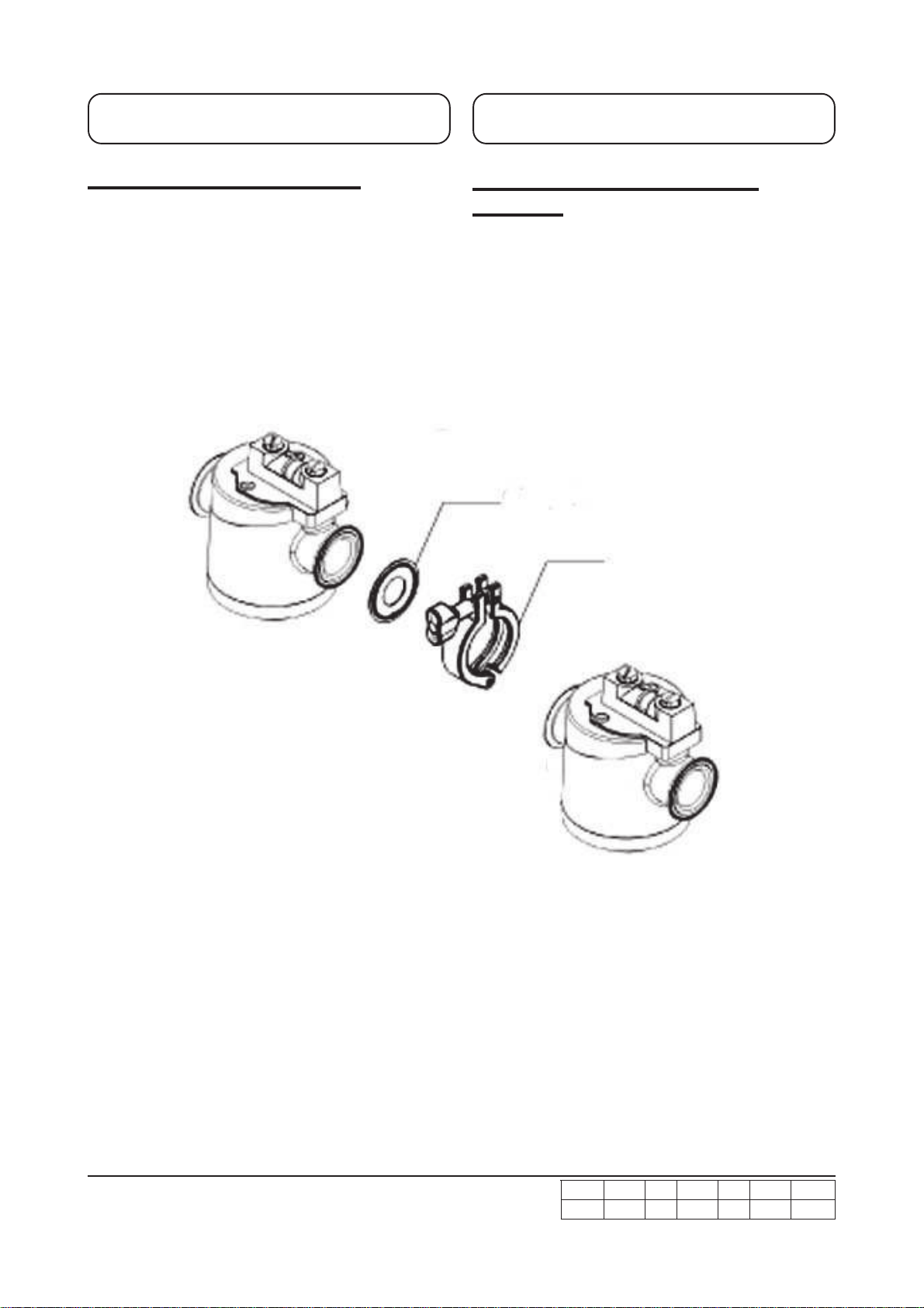
7. Montage
7.6.2 Filter-Modul-Direktanschluß
Das entsprechende Verbindungsmaterial ist als Bestellset er-
hältlich.
Bestell-Nr.: 99129105 (Filtergehäuse -02 bis -04)
Bestell-Nr.: 99129106 (Filtergehäuse -06 bis -08)
Bestell-Nr.: 99129107 (Filtergehäuse -10 bis -12)
Bestell-Nr.: 99129108 (Filtergehäuse -13 bis -17)
∗Setzen Sie die Dichtung in die Nut und drücken Sie die
Filterköpfe zusammen.
∗Verbinden der Rohrschellen.
7. Mounting
7.6.2 Direct filter-to-filter (modular)
connection
Sold as kit.
Order-No.: 99129105 (Filter housing -02 ... -04)
Order-No.: 99129106 (Filter housing -06 ... -08)
Order-No.: 99129107 (Filter housing -10 ... -12)
Order-No.: 99129108 (Filter housing -13 ... -17)
∗Install gasket.
∗Install clamp connector.
Dichtung
Gasket
Schelle
Clamp
- 18 -
8590F 41.60.03 KS 41.60.02 DT
emaN-D tlletsre emaN .rpeg emaN .ftztesre .dtztesre
8. Inbetriebnahme, Betrieb
8.1 Bereitschaft zur Inbetriebnahme
Druckluftfilter/ -systeme sind bereit zur Inbetriebnah-
me, wenn:
•Derauf dem Typenschild angegebeneDruck dem maxima-
len Betriebsdruck nicht übersteigt.
•Sie entsprechend Kapitel 7. „Montage“ installiert wurden.
•AlleZu- und Ableitungen sachgerecht angeschlossensind.
•Die erforderlichen Energien verfügbar sind.
•Absperrorgane(z.B. Ventil,Kugelhahn) in der Druckluftein-
und austrittsleitung geschlossen sind.
•Kondensat durch die Kondensatableitung ungehindert ab-
fließen kann.
•Der elektronisch gesteuerte Kondensatableiter an das
elektrische Spannungsversorgungsnetz mit der richtigen
Betriebsspannung angeschlossen ist. (Nur bei elektro-
nisch gesteuerten Kondensatableitern)
•Das Filter/ -system mit den richtigen Filterelementen aus-
gerüstet ist.
8.2 Inbetriebnahme, Betrieb
Vor der Inbetriebnahme ist sicherzustellen, daß alle Be-
dingungen des Abschnittes 8.1 „Bereitschaft zur Inbe-
triebnahme“ erfüllt sind.
Setzen Sie das Filter/ -system durch langsames Öffnen
der Drucklufteintritts- und austrittsleitung unter Druck.
Schließen Sie das Absperrorgan im Bypass
(falls vorhanden).
Das Filter/ -system ist nun in BETRIEB.
8. Start-up, operation
8.1 Preconditions for starting the filter
The filter/ -system is ready for starting when:
•Check unit serial number tag to verify working pressure.
•They has been installed in accordance with section 7.
„Mounting“.
•All inlet and outlet lines have been correctly connected.
•The required forms of energy are available.
•The shut-off devices (e.g. ball valve) in the compressed-air
inlet and outlet lines are closed.
•The condensate is able to flow through the condensate
drain without obstruction.
•The electronical condensate drain has been connected
to the electric power supply system with the correct
operating voltage (only electronical condensate drains).
•The filter/ -system is equipped with the right cartridges.
8.2 Start up, operation
Before starting the filter, ensure that all the requirements
specified in section 8.1 „Precondi- tions for starting the
filter“ have been fulfilled.
Place filter/ -system under pressure gradually by
slowly opening the compressed air inlet/outlet.
Close the shut-off device in the bypass (if installed).
The filter/ -system is now OPERATIVE.

- 19 -
8590F 41.60.03 KS 41.60.02 DT
emaN-D tlletsre emaN .rpeg emaN .ftztesre .dtztesre
8. Inbetriebnahme, Betrieb
8.3 Differenzdruckanzeige/
Differenzdruckmanometrer
Das Differenzdruckmanometer informiert als Störanzeige über
eine atypische Verschmutzung.
Unabhängig von der Differenzdruckanzeige
müssen die Filterelemente gemäß der Wartungs-
intervalle gewechselt werden. (Siehe Kapitel 9)
Das Filter CF benötigt keine Differenzdruckanzeige.
8. Start-up, operation
8.3 Differential pressure indicator/
Differential pressure gauge
Thedifferential pressure gauge indicates optimumtime for element
change.
We recommend installing a new filter cartridge
according to the maintenance periods. (See chapter
9)
The CF filter does not require a differential
pressure gauge.
- 20 -
8590F 41.60.03 KS 41.60.02 DT
emaN-D tlletsre emaN .rpeg emaN .ftztesre .dtztesre
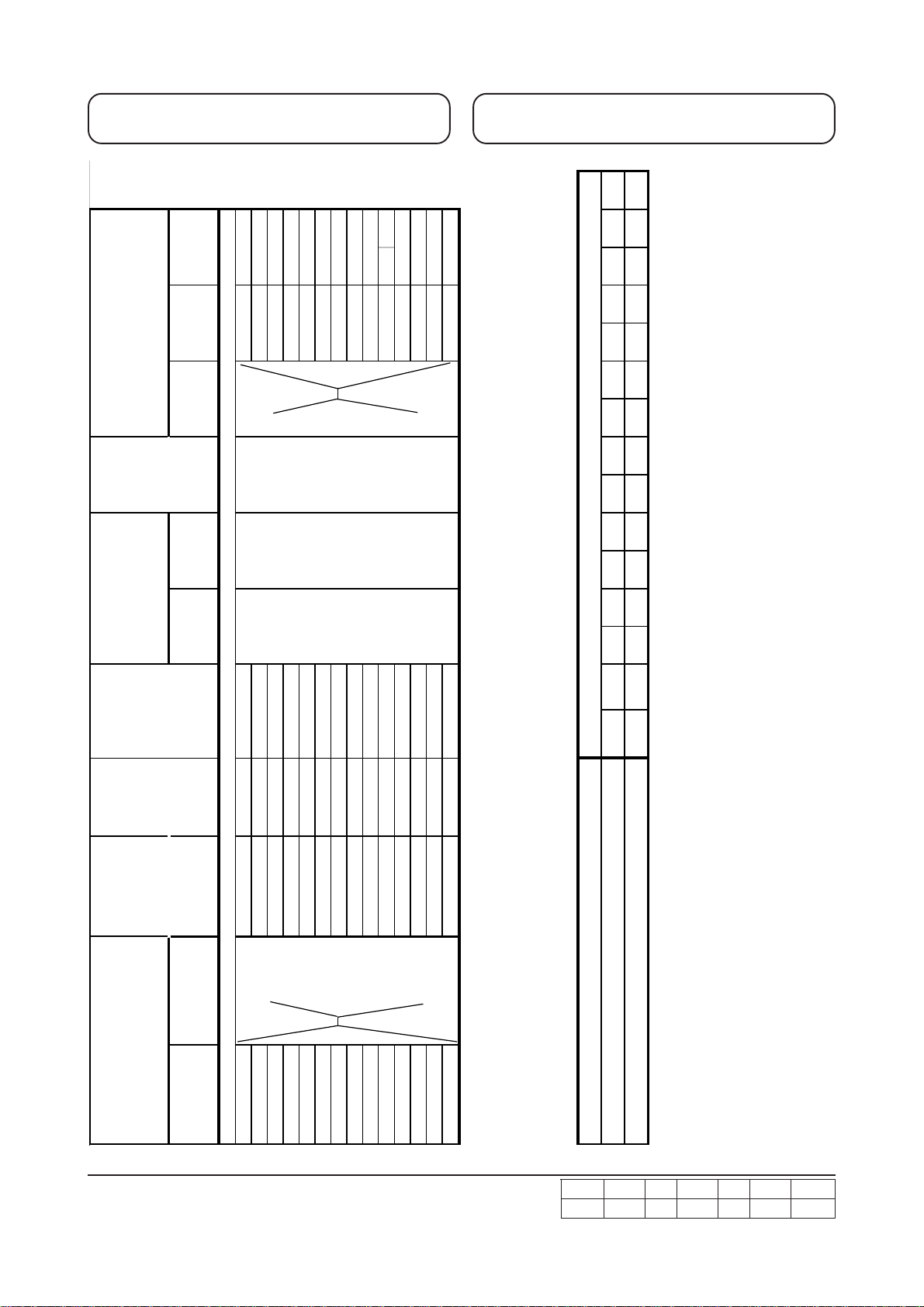
9. Wartung
9.1 Standzeit der Filterelemente
Die Standzeit der Filterelemente ist abhängig von der Beladung.
Mit steigender Beladung der Elemente erhöht sich der Differenz-
druck über den Filter (gilt nicht für Serie CF).
Die Filterelemente müssen gemäß unten stehender Tabelle ge-
wechselt werden.
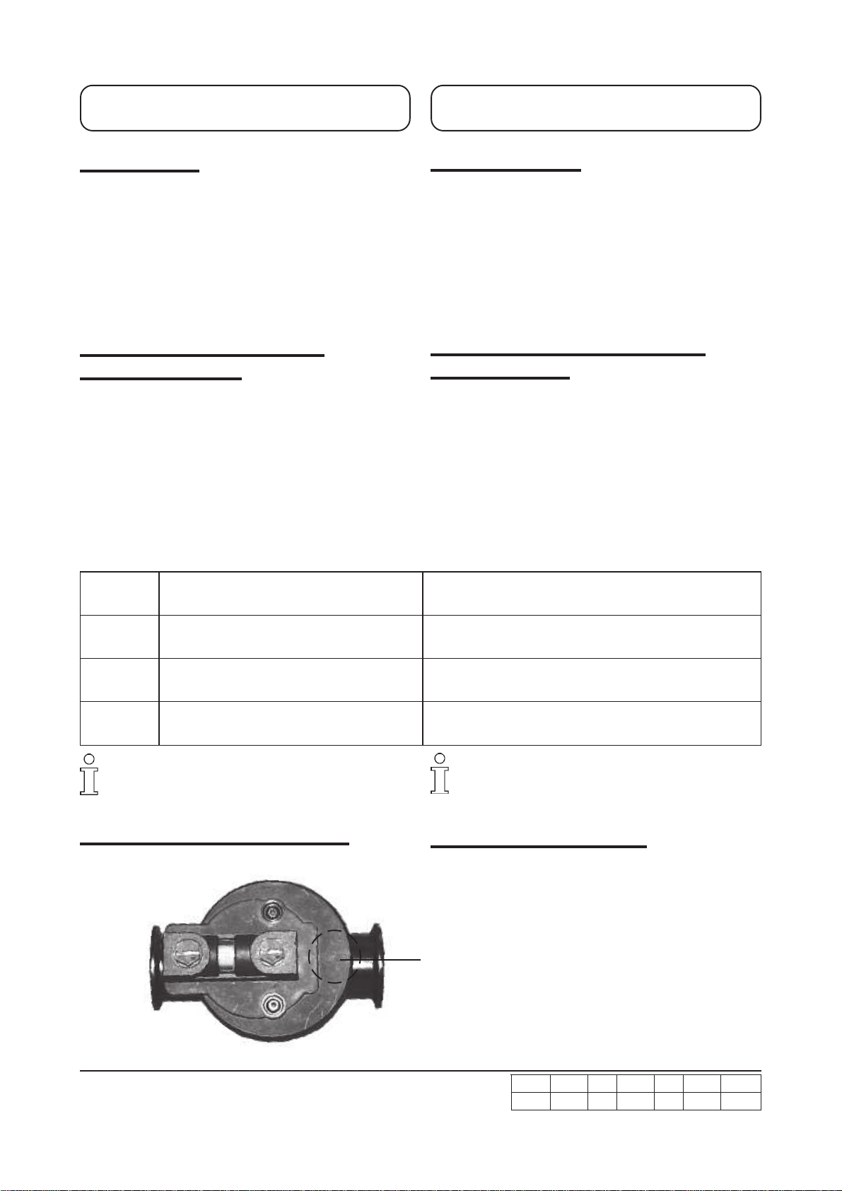
9.2 Austausch der Filterelemente
Anzahl der Filterelemente: 1 Stück
Warnung!
•Öffnen und Schließen Sie das Filter nicht mit Gewalt.
•Das (die) Filter beinhaltet(n) unter erhöhtem Druck stehen-
de Systeme.
Vor Servicearbeiten sind sie drucklos zu machen.
Absperrvorrichtung im Druckluftein- und -austritt
schließen.
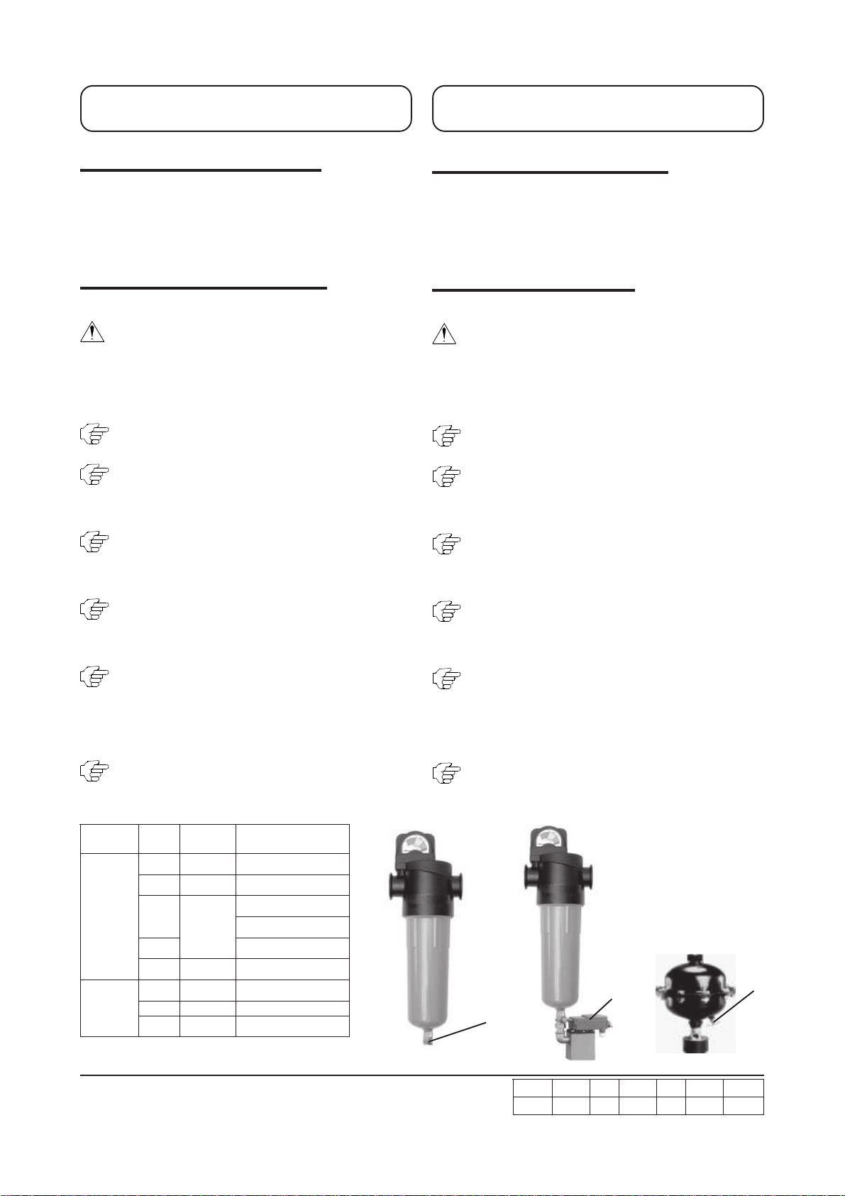
Kondensatableitungsschlauch an (1) lösen.
(Nur bei SF, PF, HF, UF).
Bei Ableiter Nr. 99129025:
Rändelschraube (1) langsam im Uhrzeigersinn lösen.
Das Filtergehäuse wird entlüftet.
Bei Ableiter Nr. 99130505:
Entlüftungsschraube (3) entgegen dem Uhrzeigersinn
lösen. Das Filtergehäuse wird entlüftet.
Beim EDD & X-DRAIN®:
Über den niveaugesteuerten Kondensatableiter kann die
Anlage drucklos gemacht werden.
- Betätigen Sie die TEST-Taste (2) am niveaugesteuerten
Kondensatableiter bis das Gerät drucklos ist.
Serie CF:
Kugelhahn öffnen.
Wartungsintervalle / Maintenance-intervals
Bh = Betriebsstunden / Working hours
9. Servicing
9.1 Serviceable life of cartridge
The cartridge’s serviceable life depends upon the degree of
contamination.As the cartridge becomes more contaminated, the
differential pressure across the filter increases (not available for
series CF).
The filter elements must be changed according to the table below.
9.2 Replacing the cartridge
Number of cartridges: 1 piece
Warning!
••
••
•Do not force the filter open or closed.
••
••
•The filter(s) contain(s) systems under high pressure.
All pressure must be released before servicing.
Close the shut-off device in the compressed air inlet/outlet.
Loosen condensate drain hose at (1) (only on SF, PF, HF,
UFmodels).
At drain Nr. 99129025:
Slowly turn the knurled screw (1) clockwise. This will
release the air from the housing.
At drain Nr. 99130505:
Loosen the bleed screw (3) in counter clockwise direction.
This will release the air from the housing.
At EDD & X-DRAIN®:
The system can be depressurized via the level-controlled
condensate drain.
- Press the TEST-button (2) on the condensate drain
until the system is depressurized.
Serie CF:
Open the ball valve.
lietsgnutraW fotraP ecnanetniam epyT gnudnewnA noitacilppA llavretnI-sgnutraW lavretni-ecnanetniaM
/etnemelE-retliF segdirtracretlif
FP,FS retlifroV retlif-erP /hcilrhäjx1redohB000.6 raeyrepx1rohB000.6
FU,FH retliforciM /rhcilrhäjx1redohB000.3 raeyrepx1rohB000.3
FC/FH noitanibmokretliF noitanibmocretliF
)FHpyT(rhcilrhäjx1redohB000.3 )FHpyT(raeyrepx1rohB000.3
)FCpyT(rhcilrhäjx1redohB000.1 )FCpyT(raeyrepx1rohB000.1
FC/FU /rhcilrhäjx1redohB000.1 raeyrepx1rohB000.1
FC retlifelhokvitkA retlifnobrac.tcA etanoM21,hB000.1 htnom21,hB000.1
/retielbatasnednoK niardetasnednoC
tik-ecivreS retlifroV retlif-erP hB000.6
tik-ecivreS retliforciM hB000.6
tik-ecivreS noitanibmokretliF noitanibmocretliF hB000.6
3
2
1
This manual suits for next models
4
Table of contents
Other SPX Water Filtration System manuals


