aldes VentZone User manual

Product Description
ALDES North America VentZone® IAQ systems are the only central ventilation systems available that provide precisely
regulatedwhole-houseIndoorAir Qualityandcentralizedbathroomfans ina single,highlyeectiveandecient ventilation
kit. Each kit has the capability to provide low, continous IAQ ventilation and zone-based on-demand “boost” ventilation.
Optional ALDES North America fans are designed to meet ASHRAE 62.2, ENERGY STAR with IAP, LEED for Homes, and
California Title 24 (CAL GREEN) standards.
VENTZONE®SYSTEMS
RESIDENTIAL SYSTEM
SOLUTIONS
VENTZONE®IAQ CONTINUOUS
EXHAUST VENTILATION ACCESSORY KITS
Number of
Bathrooms
6” ZRT-2
(120 VAC)
CAR3®: 45-260 CFM
4” ZRT-2
(120 VAC)
CAR3®:
15-85 CFM
RECOMMENDED FAN
Sold separately
ENERGY STAR Certified*
Ventilator
2 1 1 MPVS150
3 1 2 MPVS150
4 1 3 MPVS150
ZRT-2 PROVIDING
LOW-CONTINUOUS EXHAUST
IN UNOCCUPIED BATHROOM
ZRT-2R PROVIDING
ON-DEMAND BOOST
EXHAUST IN OCCUPIED
BATHROOM
ZRT-2R PROVIDING
LOW-CONTINUOUS
EXHAUST IN
UNOCCUPIED
LAUNDRY ROOM
MPVS
©2020 American ALDES Ventilation Corporation. VZ_IAQ_ContinuousExhaust_KIT_IOM_1020. Aldes reserves the right to modify its products at any time to introduce new technologies.
For more information, contact your Aldes sales advisor, visit aldes-na.com, call 1.800.255.7749, or find us on
IOM
Additional Accessories
29 010 Electronic Push-Button Timer (15/30/60/120 minutes for ZRT Operation)
29 011 Electronic Fan/Light Timer (15/30/60/120 minutes for separate ZRT/Light Operation)

READ AND SAVE THESE INSTRUCTIONS
ZRT-R
®
AIRFLOW & ZONE CONTROL
ZONE REGISTER TERMINAL
Description
ALDES patented* Zone Register Terminals (ZRT®) are
designed to introduce exibility and dynamic control to
central ventilation systems. Used in residential applications,
the ZRT® zonally regulates ventilation where it is required
without the need for individual fans. Each ZRT® is a
combination grille, register box, and control damper.
To ensure the proper operation of the damper assembly,
do not exceed 1.0 in. w.g. of dierential pressure across the
damper door. ZRT® 6" supply models require a minimum
ow constant airow regulator.
By replacing static grilles in large central systems, the ZRT-1
model provides on-o control for on-demand ventilation.
This allows central fan downsizing and promotes energy
savings by minimizing necessary fan horsepower and
ventilation-induced heat and cooling loads on the home.
The ZRT-2 model can be used for combination low-ow
indoor air quality ventilation and on-demand high-ow
spot ventilation using the same central fan system. This
is achieved by integrating a minimum constant airow
regulator directly into the damper sub-assembly. With the
damper completely closed, the constant airlfow regulator
will allow steady, low-continuous ventilation during fan
operation. When other terminals are opened for on-
demand control of spot ventilation, the closed ZRT-2 will
maintain the set low-continuous rate through the constant
airow regulator minimum ow control. By opening the
ZRT-2’s control damper, the low-ow regulator is removed
from the air stream, allowing unrestricted maximum-boost
ventilation.
Airow rate can be set or adjusted by rotating the dial
from either side. The airow indicator will move to show
the selected CFM. The airow label has multiple dened
setpoints, but the unique adjustment mechanism of the
CAR3 allows for innite adjustability between the minimum
and maximum limits.
The ZRT® can activate fans used in central ventilation
systems.Through the use of an integral damper end-switch,
the ZRT® can trigger the remote fan to start. This provides
the distinct advantage of allowing the fan to only ventilate
specic spaces when called upon, without the need for
separate fans in each space. This is especially important
in residential bath applications using popular in-line and
multi-port fans, where low noise and a single exterior vent
penetration are desired.
IOM
ZRT-1 MODEL ZRT-2 MODEL
*U.S. Pat. No. 7,766,734
Mounting
The ZRT® is available with mounting brackets to accommodate
new or existing construction. Spanner brackets that allow
mounting to joists up to 16" on center are provided and should
be secured using the screws provided (See Figure 1). Install
additional blocking or use a single joist bracket if spacing is
greater than 16" on center.
Wiring
The ZRT® is available with 24 VAC or 120 VAC actuator motors. 120
VAC wiring options are shown in Figures 2-4, and 24 VAC wiring
options using the Zone Terminal Fan Control Center (Model ZTC)
are shown in Figures 5 and 6.
Damper
Assembly
Grille (Included)
Integral CAR3 Minimum
Flow Regulator and Damper
16” o.c.
Mounting
Brackets
(Included)
CAR3
Maximum
Flow Regulator
(Optional)
(Not Shown)
CAR3
Maximum
Flow Regulator
(Optional)
Damper
Motor
Cover

Page 2 | ZRT-R IOM FIGURE 1 - MOUNTING
MAINTENANCE SERVICE PARTS
Damper Motor 24 VAC 85 695
Damper Motor 120 VAC 85 696
Damper Assembly 24 VAC for Models w/ 4" Duct Collar 36 134
Damper Assembly 24 VAC for Models w/ 6" Duct Collar 36 136
Damper Assembly 120 VAC for Models w/ 4" Duct Collar 36 135
Damper Assembly 120 VAC for Models w/ 6" Duct Collar 36 137
Joist attachment
spanner brackets
(Included)
IMPORTANT:
Suspension
brackets must
be securely
anchored to joists.
ZRT®
Warning
TO REDUCE THE RISK OF FIRE, ELECTRIC SHOCK, OR INJURY
TO PERSONS, OBSERVE THE FOLLOWING:
1. Usethisunitonlyin themanner intendedbythemanufacturer.
If you have any questions, contact the manufacturer.
2. Beforeservicingorcleaningtheunit,switchpoweroatservice
panel and lock service panel to prevent power from being
switched on accidentally. When the service disconnecting
meanscannot belocked,securelyfastena prominentwarning
device, such as a tag, to the service panel.
3. To reduce the risk of re and electric shock, the integral
damper end switch should only be used to switch ventilation
equipment rated Maximum 10A, 1/2 HP.
4. Sucient air is needed for proper combustion and exhausting
of gases through the flue (chimney) of fuel-burning
equipment to prevent backdrafting. Follow the heating
equipment manufacturer’s guidelines and safety standards,
such as those published by the National Fire Protection
Association (NFPA), and the American Society of Heating,
Refrigerating and Air-Conditioning Engineers (ASHRAE), and
the local code authorities.
5. In addition to the following manufacturer’s instructions, it is
necessary to comply with federal, state, and local government
codes. Your purchase of this ALDES ventilation system
represents an investment in the health and comfort of the
occupants, as well as an investment in the protection of
the building from the damaging eects of excessive indoor
humidity.
6. Installation work and electrical wiring must be done by
qualied person(s) in accordance with all applicable codes
and standards, including re-rated construction.
7. When cutting or drilling into wall or ceiling, do not damage
electrical wiring and hidden utilities.
Caution
1. For general ventilating use only. Do not use to exhaust
hazardous or explosive materials and vapors.
2. Automatically operated device. To reduce the risk of injury,
disconnect from power supply before servicing.
3. ZRT®is acceptable for use over a tub or shower when
installed in a GFCI-protected circuit. If wired directly to the
fan or ZRT®, a single Ground Fault Protector on the 120 VAC
common power supply must be used to protect all devices
on the same circuit.
System Design
Satisfactory performance of a central ventilation system requires:
• Proper integration of all the components, compatible grilles,
and wall/roof caps;
• Proper duct design for friction losses;
• Consideration of acoustic and vibration properties of the fan
and its mounting;
• Acoustic properties of the grilles;
• Consideration of the mode of operation, whether continuous
or automatically controlled by dehumidistat, timer, or
occupancy sensor;
• Installation inaheated orunheatedspace,with consideration
forthepotentialof condensationinthe ductingor fanhousing.
Inspect the carton upon receipt to ensure the terminal has not
been damaged in transit. If damaged, it is the responsibility of
the recipient to le a damage claim with the carrier. ALDES is not
responsible for damage incurred during shipment.
Handle the unit with care to prevent damage to the housing and
other components. Store the unit indoors if possible. If outdoor
storage is required, protection against moisture and dirt is
necessary.
Clean the grille monthly (if so equipped).

Page 3 | ZRT-R IOM
Intermittent fan
operation using 120
VAC power supply to
ZRT-1 terminals. SPST
convenience switches,
such as manually
operated switches,
mechanical timers, or
dehumidistats, may
be used to control
each ZRT and fan in
this conguration.
Continuous fan
operation using 120
VAC power supply to
ZRT-2 terminals. The
fan and ZRT terminals
may be wired
independently.
Intermittent fan
operation using 120
VAC power supply
to ZRT-1 terminals.
SPST convenience
switches, such as
push-button timers or
motion sensors, may
be used to control
each ZRT and fan in
this conguration.
FIGURE 2
FIGURE 3
FIGURE 4

Page 4 | ZRT-R IOM
©2020 American ALDES Ventilation Corporation and ©2020 ALDES Canada. ZRT-R_IOM_0720. Aldes reserves the right to modify its products at any time to introduce new technologies.
For more information, contact your Aldes sales advisor, visit aldes-na.com, call 1.800.255.7749, or find us on
Intermittent fan operation
using 24 VAC ZTC Zone
Terminal Control Center
and ZRT-1 terminals. SPST
convenience switches, such
as manually operated,
mechanical timers, or
dehumidistats, may be used
to control each ZRT and fan
in this conguration. The
fan is controlled by the ZTC.
IntCont
-------Input------ -------Output to Fan-------
A
FIGURE 5
Continuous fan operation
using 24 VAC ZTC Zone
Terminal Control Center
and ZRT-2 terminals. SPST
convenience switches, such
as manually operated,
mechanical timers, or
dehumidistats, may be used
to control each ZRT in this
conguration. The fan may
be wired independently or
to the ZTC.
IntCont
-------Input------ -------Output to Fan-------
A
FIGURE 6

Product Description
Ventergy® Series Multi-Port Ventilators (MPVS) are highly versatile,
continuous-duty rated fan units for residential and light commercial
applications. They meet ENERGY STAR eciency criteria for low energy
consumption. The most popular use for the fan is central exhaust
ventilation of bathrooms, kitchens, laundry rooms, and other rooms
where humidity is a controlling factor since the fan has a single exhaust
discharge duct directly to the outdoors.
The principal advantage of the MPVS is the elimination of standard noisy
bath fans, with the benets of quiet operation and reduced penetrations
to the exterior of the building. With the increasingly tight construction
of energy-ecient buildings, there is a growing need for mechanical
ventilation for indoor air quality. These fans are designed to serve this
purposebyprovidingeectivebathroomventilationwiththeabilitytorun
intermittently or continuously. The quiet, energy-ecient, permanent-
split-capacitor type of external-rotor motor has permanently sealed
bearings that provide many years of maintenance-free performance.
Construction
The MPVS is constructed of heavy-gauge galvanized steel to prevent
corrosion caused by moisture. The cabinet is internally lined with
acoustic, closed-cell foam insulation that acts as a vapor barrier. This
allows installation directly above living spaces or in unheated plenum
spaces without concern for noise or condensation.
Controls
The fans can be operated manually or automatically by a programmable
timer or dehumidistat. They may also be operated in conjunction with
a variable speed control.
Ducting the Fan
Theducting from this fantotheoutside ofthe buildinghasastrongeect
ontheairow,noise and energyuseofthefan.Usetheshortest,straightest
duct routing possible for best performance, and avoid installing the fan
with smaller ducts than recommended. Insulation around the ducts can
reduce energy loss and inhibit mold growth. Fans installed with existing
ducts may not achieve their rated airow.
Use ductwork of a diameter that is the same as or greater than the
diameter of the duct connectors on the fan.
MPVS150 & MPVS200
VENTERGY®SERIES FANS
WARRANTY
3 YEARS
MULTI-PORT EXHAUST VENTILATORS
Fan and Motor
The fan motor is an energy-ecient, permanent-split-capacitor type
of external-rotor design.Totally sealed to protect against moisture and
contaminants, it is approved for removing steam and moisture from
kitchenand bathareas.The motor incorporatespermanentlylubricated
andsealedbearingsandautomatic-resetthermal-overloadprotection.It
isdesignedand certiedforcontinuousdutyor intermittentoperation.
The fan uses a backward-inclined impeller design that prevents dust
from collecting on the blades. Each fan is statically and dynamically
balanced in the factory to eliminate vibration and ensure quiet
operation. The entire motor and fan assembly is mounted on a drop-
down hinged access panel for simple service and inspection, and it can
be removed from the fan without disassembling the duct connections.
Locating and Installing
The compact dimensions and versatile mounting options permit
installation above drop ceilings, between ceiling joists, or within a small
sot location. They can be installed horizontally or vertically.
Accessories
Accessorykitsareavailabletofacilitateinstallationandenhanceoperation.
Accessories kits are sold separately. Please visit aldes-na.com, or contact
your local Aldes distributor for details.
Performance
Fan airow and energy performance shall be tested in accordance with
HVI procedures.
IOM
READ AND SAVE THESE INSTRUCTIONS

Page 2 | MPVS150 & MPVS200
ELECTRICAL DATA
MPVS150: 115 V, 60 Hz, 41 W, 0.34 A, 2200 RPM
MPVS200: 115 V, 60 Hz, 59 W, 0.53 A, 2960 RPM
Above ratings are intended for sizing electrical wiring only.
Actual consumption will be lower.
Dimensions & Performance
Drop-down
hinged access
panel for simple
service and
inspection
FRONT VIEW
TOP VIEW
WARRANTY
3 YEARS
ELECTRICAL AND AIRFLOW PERFORMANCE*
Model
Watts
at 0.2"
Ps
CFM vs. Static Pressure ENERGY
STAR
Certied
0" 0.2" 0.4" 0.6" 0.8" 1.0" 1.2" 1.4" 1.6
MPVS150 39.9 212 170 133 101 71 49 17 -- --
MPVS200 62.5 287 250 227 198 168 136 100 65 24
*Certied airow rating at 0.2" w.g. is derated from actual test results per HVI Certication procedure 920.
The HVI Certied Rate for MPVS150 = 170 CFM, MPVS200 = 250 CFM.
8
"
12
"
13-1/2
"
12
"
1-3/4" 1-3/4"
1-3/4"
1-3/4"
6
"
6
"
6
"
4
"
4
"
4
"
4
"
4
"
4
"
8
"
12
"
13-1/2
"
12
"
1-3/4" 1-3/4"
1-3/4"
1-3/4"
6
"
6
"
6
"
4
"
4
"
4
"
4
"
4
"
4
"
NOTE: Location(s) of eld-installed 4"
side-tap collar(s) shown as dashed lines.
*This table should only be used as a general guide. Actual duct length allowances may be longer on some models. Contact the factory for assistance.
NOTE: 3”Ducting may be substituted to permit installation in partition walls. Smaller diameter ducting has increased resistance to airow. For each foot of 3” ducting substituted for 4” diameter duct, reduce the
allowable duct length by 3 feet. If duct runs longer than permitted in the table above are required, use smooth ducting and/or increase the diameter.
AIRFLOWS AND DUCT LENGTHS*
REFERENCE RDF INSTALLATION SUPPLEMENT FOR ADDITIONAL
INSTRUCTIONS AND WARRANTY INFORMATION.
TOTAL
EXHAUST
RATE CFM
FAN DISCHARGE DUCT
Assumes low-pressure drop-vent cap FOR EACH
ELBOW DEDUCT
6" SMOOTH 4" FLEXIBLE
175 20 ft. 10 ft.
4" Diameter = 4 ft.
6" Diameter = 7 ft.
200 15 ft. 8 ft.
225 13 ft. 7 ft.
AIRFLOW
CFM
INTAKE DUCT TO FAN
Recommended Max. Duct Length from Grille to Fan (ft.)
4" SMOOTH 4" FLEXIBLE 6" SMOOTH 6" FLEXIBLE
50 50 30 400 250
60 40 20 280 175
80 -- -- 170 95
100 -- -- 110 70

Page 3 | MPVS150 & MPVS200
©2020 American ALDES Ventilation Corporation. MPVS150 & MPVS200_IOM_1020. Aldes reserves the right to modify its products at any time to introduce new technologies.
For more information, contact your Aldes sales advisor, visit aldes-na.com, call 1.800.255.7749, or find us on
WARRANTY
3 YEARS
Small dimples or "scratches" are machined on the fan housing to aid in using the #8-3/4" self-tapping screws
(provided) for mounting bracket installation. The locations are represented in the diagram below. To prevent
potential damage to internal parts, DO NOT use screws or washers other than those provided. Use four (4)
screws and washers for each bracket.
GROMMET
WASHER
MOTOR
ACCESS
DOOR
Additional 4" collar(s) may be provided
for eld installation, depending on your
specic model. Collars are installed on the
side(s) of the base MPVS at the knock-out
locations as indicated below.
1.
2.
MOUNTING BRACKET LOCATIONS
(1) Remove the metal knock-out using
a slot-type screw driver or similar tool.
Make one rm hit to holding tabs. The
liner applied to the inside of the knock-out
should break away from the fan liner, but
additional trimming with a sharp knife may
also be required (pull out from the inside of
box). (2) Attach the collar(s) provided using #8-1/2" screws
(also provided).
MPVS150/MPVS200 SCHEMATIC
*Sold separately
†Refer to IOM text for details
Duct joints, and ceiling
and wall penetrations
should be sealed†
WALL HOOD
OR ROOF CAP* FAN HOUSING
(Insulation may be installed
over the fan housing)†
DUCTWORK*†
EXHAUST
GRILLES*†
BACKDRAFT DAMPERS*†
EXHAUST
GRILLE*†
BACKDRAFT
DAMPER*†

Installation
Upon receipt, inspect the carton to ensure the fan has not been
damaged in transit. If damaged, it is the responsibility of the
recipient to le a damage claim with the carrier. ALDES North
America is not responsible for damage incurred during shipment.
Handle the unit with care to prevent damage to the housing and
other components. Store the unit indoors if possible. If outdoor
storage is required, protection against moisture and dirt is
necessary.
Unpack the unit, taking care to look for any loose components
among the packing material. Make certain that the fan housing
and the blower are free of any loose packing material or small
parts. If not removed before startup, damage and injury may
result from solid objects discharged by the blower. Inspect for
damaged, loose, or missing parts.
A location should be chosen that will minimize the length of
duct runs and the number of elbows that are required. If more
than four (4) 90oelbows are required, 45oelbows should be
used. If insulated exible duct is used, the inner sleeve should
be fully expanded over the entire duct run. Any turns that are
necessary in the exible duct run should be made as gradually
as possible. Choose roof and/or wall caps that are of a more
open, less restrictive design. The perimeter of all ceiling and wall
penetrations for ductwork and grille(s) should be properly sealed
with caulk or a similar material to ensure that there is not an air
leakage path between the device and the wall and/or ceiling.
Install the unit in its nal location. The fan may be installed in
a mechanical room, crawl space, or attic. It is designed to be
placed on a at surface, against a wall or trusses, or suspended
from above. If set on a at surface, vibration-isolation pads are
recommended. Mounting brackets with rubber grommets
are supplied to permit installation against a vertical surface or
from the ceiling. Alternately, the fan may be suspended using
threaded rods or chains. At least 12 inches clearance from the
access panel is needed to permit servicing the motor. Loose ll
or batt insulation can be installed over the unit if the unit’s access
doors can still be opened.
VENTERGY®SERIES FANS
RECTANGULAR DUCT FAN
RDF
INSTALLATION SUPPLEMENT
Mounting
(Dierences in bracket type and conguration may exist on
some derived models. Refer to supplement where appropriate).
Orient the fan so that the access door can be opened for service.
Tools Required:
Power screwdriver with No. 2 Phillips bit.
Mounting brackets are supplied with the fan. The brackets may
be mounted to the fan using the self-drilling screws and rubber
grommets provided, at the locations indicated by dimple marks
on the side and bottom panels of the fan. Pan head number
10 screws are provided to attach the mounting bracket to the
building framing members. It may be necessary to add additional
framing members to span wall studs. It is not recommended to
use drywall anchors to support the fan. If installed against a
concrete or masonry wall, concrete anchors are recommended.
The rubber grommets provide vibration isolation. The brackets
should be attached to the fan rst. Then install the wood screws
at the keyhole locations and install the fan.
The fan may also be mounted on a foam rubber pad on a at
surface, such as an attic oor.
Cold Climate Precautions
If installed in an unheated space in cold climates, there is a
possibility of condensation forming in the fan housing or ducting
components. A backdraft damper installed at each grille is an
eective way to reduce the potential for condensation when
the fan is cycled on and o. Insulated ducting must be used
where exposed to cold attic or crawl space temperatures to avoid
condensation in the ducting. Condensation can also be avoided
by continuous operation of the fan.
IOM
READ AND SAVE
THESE INSTRUCTIONS
For the following base models:
RDF 8-8IP, RDF 8-8MAX, RDF 12-8IP, RDF 12-8
(See supplemental instructions for derived models withduct adapters,
manifolds, etc., as appropriate for your particular model.)
WARRANTY
3 YEARS
FANS MAY BE
MOUNTED VERTICALLY
OR HORIZONTALLY

Page 2 | RDF Installation Supplement
Caution
FOR GENERALVENTILATING USEONLY.DO NOT USETO EXHAUST
HAZARDOUS OR EXPLOSIVE MATERIALS AND VAPORS.
Warning
TO REDUCETHE RISK OF FIRE, ELECTRIC SHOCK, OR INJURYTO
PERSONS, OBSERVE THE FOLLOWING:
1. Usethisunitonlyinthemannerintendedbythemanufacturer.
If you have any questions, contact the manufacturer.
2. Beforeservicingorcleaningtheunit,switchpoweroatservice
panel and lock service panel to prevent power from being
switched on accidentally. When the service disconnecting
means cannot belocked, securelyfasten a prominent warning
device, such as a tag, to the service panel.
In addition to the following manufacturer’s instructions, it is
necessary to comply with federal, state, and local government
codes. Your purchase of this ALDES North America system
represents an investment in the health and comfort of occupants,
as well as an investment in the protection of the building from the
damaging eects of excessive indoor humidity.
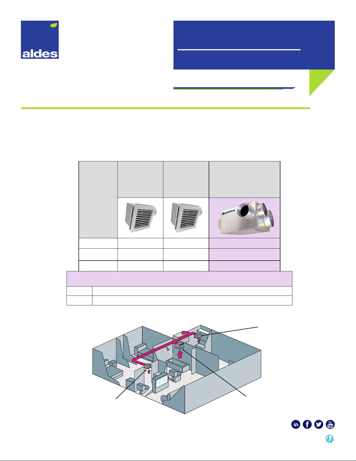
This model of centrifugal fan is designed for multiple purposes. It
may be used as an in-line rectangular duct fan (Model RDF) or a
manifolded, multi-port fan for multiple exhaust or supply points.
It may be installed in a remote location such as an attic space,
mechanical room, above a drop ceiling, in a closet or in a laundry
room, to provide quiet exhaust of stale, humid, or otherwise
polluted air from bathrooms, kitchens, laundry rooms, or storage
rooms via exhaust grilles and ducting to the centrally located
fan, which is ducted to the outdoors. With small return grilles
in bedrooms and other areas, and one duct connection to the
outdoors, such as the BVS models, it may also be used as a supply
ventilator or recirculating central ventilator for the introduction
of outdoor air, raising the temperature of the fresh air by
mixing with recirculated indoor air. When used with adjustable
balancing grilles or ALDES Constant Airow Regulators (CAR) and
compatible roof/wall caps, ducting, etc., the fan is the heart of a
complete pre-engineered ventilation system.
System Design
Satisfactory performance of a central ventilation system requires
the proper integration of all the components:
• Fan selection for airow, pressure and acoustic properties,
vibration characteristics and mounting method, and mode of
operation (continuous, manually or automatically controlled)
• Proper duct design for friction losses, with compatible supply
or exhaust grilles (airow and acoustic properties of the supply/
exhaust grilles), and compatible wall/roof caps
• Method of balancing airows of multi-point ventilation systems
• Consideration for potential condensation in the ducting or fan
housing (installation in an unheated space)
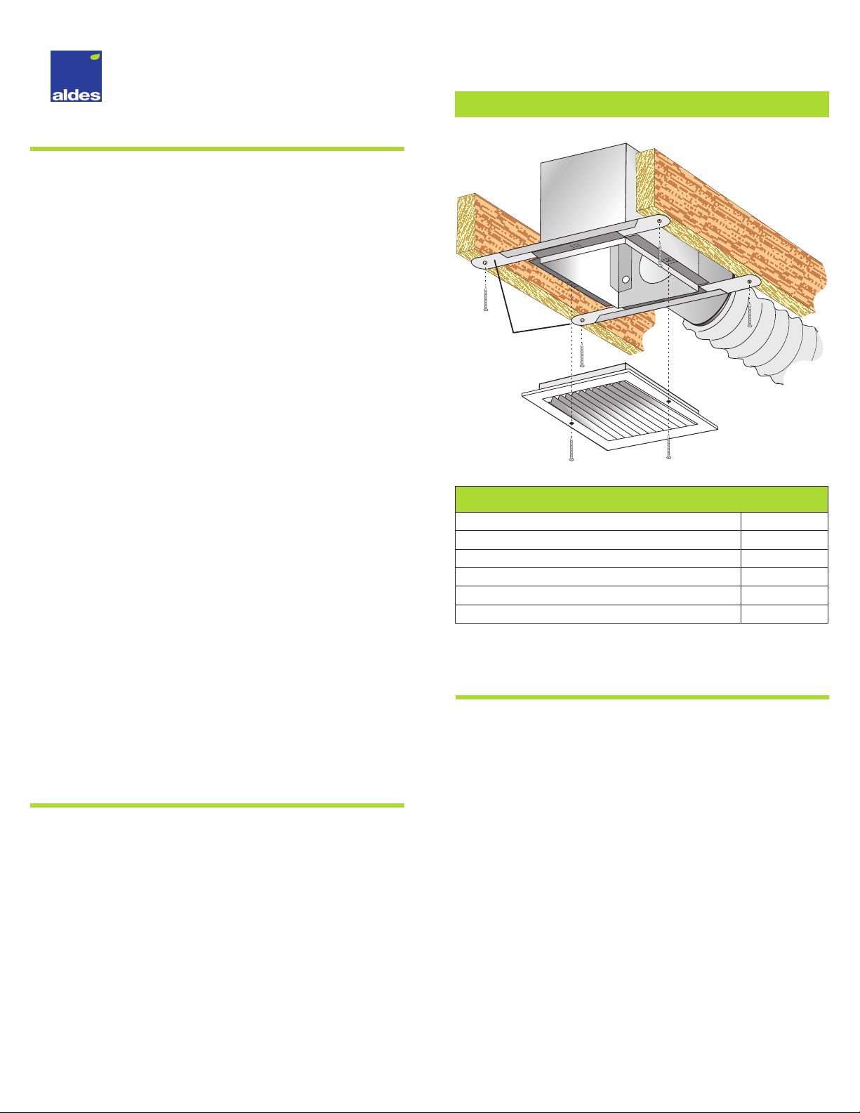
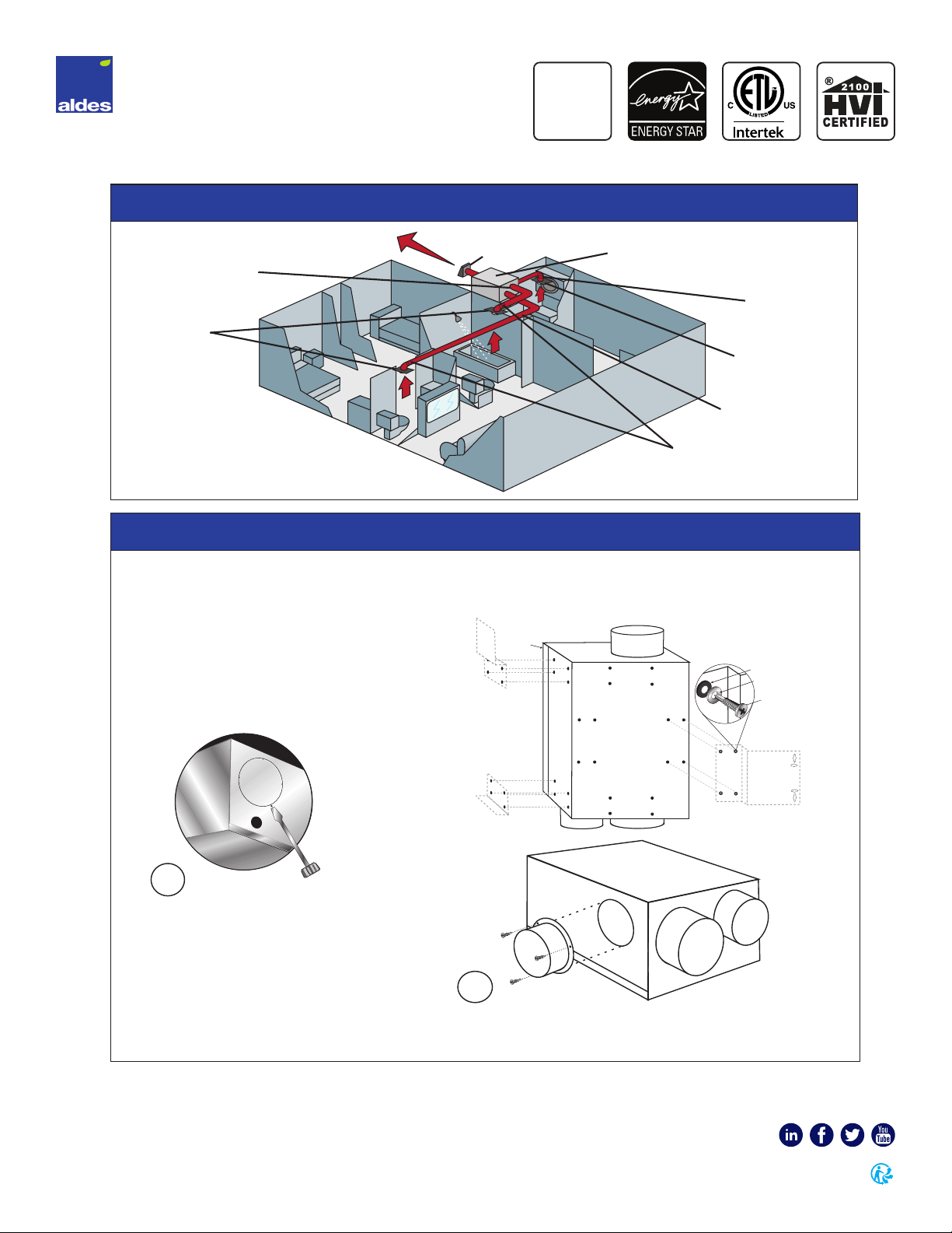
Duct Connections
Ducting may be exible or rigid, depending on local codes. If
permitted by code, insulated exible ducting is recommended.
To limit fan noise, at least 8 feet of insulated exible duct shall
be installed between the fan and grille(s). All exible duct
connections shall be secured with clamps or wire ties and
sealed with mastic or code-approved duct tape. All rigid ducts
are to be sealed on both ends and along the longitudinal seams
with mastic or code-approved duct tape.
Ducting shouldconform toNFPA90A and meettherequirements
of UL as a Class 0 or Class 1 duct to specication UL 181, Standard
for Factory-Made Air Ducts and Duct Connectors.
Installation Warning
TO REDUCE THE RISK OF FIRE, ELECTRIC SHOCK, OR INJURY
TO PERSONS, OBSERVE THE FOLLOWING:
1. Installation work and electrical wiring must be done by
qualied person(s) in accordance with all applicable codes
and standards, including re-rated construction.
2. Sucient air is needed for proper combustion and
exhausting of gases through the ue (chimney) of fuel-
burning equipment to prevent backdrafting. Follow the
heating equipment manufacturer’s guidelines and safety
standards such as those published by the National Fire
Protection Association (NFPA), the American Society for
Heating, Refrigeration and Air Conditioning Engineers
(ASHRAE), and the local code authorities.
3. When cutting or drilling into wall or ceiling, do not damage
electrical wiring and other hidden utilities.
4. When used as exhaust fans, ducted fans must always be
vented to the outdoors.
5. If this unit is to be installed over a tub or shower, it must
be marked as appropriate for the application and be
connected to a GFCI- (Ground Fault Circuit Interrupter)
protected branch circuit.
6. NEVER place a switch where it can be reached from a tub
or shower.
MAINTENANCE
MONTHLY:Inspect and clean the exhaust grilles and
lters, if so equipped.
ANNUALLY: To ensure the maximum eciency of the
fan unit, it is recommended to clean the inside of the
fan box as well as the blower wheel.

Electrical Data
Provide disconnect switch in vicinity of fan to permit servicing
fan in accordance with NEC and local codes.
Depending on the desired mode of operation, switches may be
simple on-o switches, motor speed controls, timer switches,
time delay, time-of-day cycle timers, dehumidistats, occupancy
sensing controls, controllers, etc., provided they are rated for
the motor duty and meet the nameplate electrical ratings of
the motor. (Additional application wiring diagrams illustrating
a variety of controls for use with RDF fans are available by
calling the factory at 1-800-255-7749.)
Caution
AUTOMATICALLY OPERATED DEVICE. TO REDUCE RISK
OF INJURY, DISCONNECT FROM THE POWER SUPPLY
BEFORE SERVICING.
Disassembly
Turn o all power to the unit. The blower may be inspected
and cleaned by removing the two screws from the hinged
access panel. The blower assembly can now be swung open
for cleaning the wheel.
Page 3 | RDF Installation Supplement
Base Model Volts Max
Amps
Max
Watts RPM
RDF 8-8IP 115 0.19 20 2324
RDF 8-8MAX 115 0.29 34 3135
RDF 12-8IP 115 0.34 41 2200
RDF 12-8 115 0.53 59 2960
Disclaimer
IT IS THE RESPONSIBILITY OF THE CONTRACTOR/INSTALLER
TO DETERMINE THE SUITABILITY OF THIS EQUIPMENT
WITH RESPECT TO THE POTENTIAL FOR BACKDRAFTING
NATURALLY VENTED FLUE DEVICES AND/OR AFFECTING
RADON ENTRY.
Impact of Exhaust Fans
In especially tight homes heated with naturally vented
appliances, such as gas, oil or wood-red furnaces, boilers,
stoves or replaces, the exhaust system may produce sucient
negative pressure indoors to induce the backdrafting of ue
gases. This is a common, though intermittent, occurrence, with
conventional exhaust systems, such as vented kitchen range
hoods, clothes dryers, bath fans, etc. In the case of continuous
exhaust, though often at lower ow rates, the potential for
backdrafting the ue of these appliances does exist and
represents a dangerous situation.
The International Fuel Gas Code, Appendix D provides a
Recommended Procedure for Safety Inspection of an Existing
Appliance Installation. This procedure should be followed to
determine the presence of adequate combustion air while all
exhaust fans are operating at maximum speed and all doors
and windows are closed.
In the event that backdrafting occurs, steps must be taken
to provide sucient combustion air to the furnace or boiler,
following the guidelines of the National Fuel Gas Code and all
state and local codes.
RDF 8-8MAX and RDF 12-8 RDF 8-8IP and RDF 12-8IP

Mechanical Supply Fans
Mechanical supply of outdoor air tends to reduce the
potential and frequency of backdrafting by reducing
the contributing negative pressures; however, due
to a multitude of factors, including the wide range
of exhausting appliances that may be present, the
eects of wind and building shape, the presence of
multiple chimneys, building leakage, and the use of
operable windows, no one can assure elimination of
backdraft conditions so long as atmospherically vented
combustion equipment is present in the home.
ALDES North America accepts no liability for backdraft conditions resulting from negative pressures. Nor does ALDES North America
make representation that blending supply ventilators (BVS) are adequate to prevent such occurrences.
REPLACEMENT PARTS LIST (BASE MODELS)
Model Motor
P/N
Impeller
Dimensions (mm)
Capacitor
P/N Cap
RDF 8-8IP* 86 561 133 x 42 86 172 4uF
RDF 8-8 MAX 86 561 133 x 45 86 172 4uF
RDF 12-8IP* 86 562 180 x 35 86 179 10uF
RDF 12-8 86 562 180 x 35 86 170 5uF
*Designates Impedance Protection with alternate wiring of capacitor across auxiliary winding of motor.
Page 4 | RDF Installation Supplement
METAL DUCT
RDF RDF
FLEXIBLE DUCT
CEILING
GRILLE
WITHIN 30"
OF COOK
SURFACE USE
METAL DUCT
ONLY
FLEXIBLE DUCT
ACCEPTABLE
OR AS REQUIRED
BY LOCAL
BUILDING CODE
30"
CEILING
OVER
30"
For installations in which the fan is connected to a range hood, or if an exhaust grille connected to the fan is located near the cooking surface (as shown below),
be sure to observe the following safety warnings:
Warning
TO REDUCE THE RISK OF FIRE, USE ONLY GALVANIZED STEEL
DUCTWORK WHEN REQUIRED TO USE METAL DUCT.
NOTE: If only rigid ducting is allowed, a metal sound attenuator
shall be installed between the fan and the range hood.
NOTE: If the fan is not connected to a range hood or a grille in the
vicinity of the cooking surface, other approved ducting may be used
as described in the “Duct Connections” section of basic instructions.
Range Hood/Cooking Surface Warning
TO REDUCE THE RISK OF INJURY TO PERSONS IN THE EVENT OF A RANGE-TOP GREASE FIRE, OBSERVE THE FOLLOWING:
1. Never leave surface units unattended at high settings. Boilovers cause smoking and greasy spillovers that may ignite.
Heat oils slowly on low or medium settings.
2. Always turn range hood ON when cooking at high heat or ambeing food.
3. Clean ventilating fans frequently. Grease should not be allowed to accumulate on fan or lter. Use proper pan size.
Always use cookware appropriate for the size of the surface element.
4. SMOTHER FLAMES with a close-tting lid, cookie sheet, or metal tray, then turn o the burner. BE CAREFUL TO PREVENT
BURNS. If the ames do not go out immediately, EVACUATE AND CALL THE FIRE DEPARTMENT.
5. NEVER PICK UP A FLAMING PAN - You may be burned.
6. DO NOT USE WATER, including wet dishcloths or towels, because a violent steam explosion could result.
7. Use an extinguisher ONLY if:
1. You know you have a Class ABC extinguisher, and you already know how to operate it.
2. The re is small and contained in the area where it started.
3. The re department is being called.
4. You can ght the re with your back to an exit. Based on “Kitchen Fire Safety Tips” published by NFPA.

Page 5 | RDF Installation Supplement
©2020 American ALDES Ventilation Corporation and ©2020 ALDES Canada. RDF_InstallationSupplement_IOM_1020. Aldes reserves the right to modify its products at any time to introduce new technologies.
For more information, contact your Aldes sales advisor, visit aldes-na.com, call 1.800.255.7749, or find us on
3 Year Warranty: This Warranty Supersedes All Prior Warranties
DURING THE FIRST 30 DAYS:
ALDES will repair or replace any product
that has a factory defect in workmanship
or material. Product(s) may be returned to
point of purchase or the ALDES factory,
with Bill of Sale, for an immediate
replacement.
DURING THE FIRST 3 YEARS:
(Excluding the 30-day period above)
ALDES will repair or replace any product
that has a factory defect in workmanship
or material. Product(s) must be returned
to the ALDES factory, with Bill of Sale and
identied with an RMA number, within 3
years of purchase. The warrantee assumes
all costs to and from the factory.
WARRANTY DOES NOT APPLY TO THE
FOLLOWING:
1.
Damages from shipping, either
concealed or visible. Claim must be
led with the carrier.
2.
Damages resulting from improper
wiring or installation.
3.
Damages or failure caused by Acts
of God, or resulting from improper
consumer procedures, such as:
-Improper maintenance
-Misuse, abuse, abnormal use, or
accident
-Incorrect electrical voltage or
current
-Removal or alterations made on
the ALDES label, control number,
or date of manufacture.
4.
Any other warranty, expressed,
written, or implied, and to any
consequential or incidental damages,
loss of property, revenues, or prot,
or costs of removal, installation,
or reinstallation, for any breach of
warranty.
WARRANTY VALIDATION
The end user must keep a copy of the
Bill of Sale to verify purchase date. Valid
proof of the date of installation may also
serve as a verication of commencement
of warranty period.
ALDES RETURN POLICY
Claims for damages or order shortages
must be reported within 10 days of receipt
of product(s). For any product(s) received
damaged by the forwarding agent, the
following instructions MUST BE followed:
1. For product(s) delivered by UPS:
-Concealed Damages: Keep all
cartons; call UPS for an inspection
and notify ALDES immediately.
-Visible Damages: Save all cartons
and le a complaint directly with
UPS.
2.
For product(s) delivered by Common
Carrier: File damaged goods claim
directly with the freight company.
3.
Shortages: Only sign for the total
number of pieces received and
contact ALDES immediately.
FOR FACTORY RETURN
ALDES WILL NOT ACCEPT THE RETURN OF
ANY SPECIAL, NON-STOCK, OBSOLETE, OR
UNSALABLE PRODUCT(S). ALDES MAY,
AT ITS DISCRETION, ACCEPT RETURN OF
SALABLE PRODUCT(S) SUBJECT TO A 25%
RESTOCKING CHARGE.
1.
No product(s) will be accepted
without a Return Materials
Authorization (RMA) number. RMA
number can be obtained by calling
ALDES at 1-800-255-7749. Have
the Bill of Sale or proof of date of
installation available.
2.
RMA must be clearly marked on
outside of carton or delivery will
be refused. All product(s) must be
returned freight prepaid.
3.
Product(s) will be repaired/replaced
and shipped back to buyer; no credits
will be issued.
4.
Any out-of-warranty product will be
evaluated and buyer will be notied
of cost. Repair cost will be charged to
customer. Buyer will be responsible
for return freight, or product may
be returned to the buyer, freight
collect, without action. No credit
will be issued.
LIMITATIONS OF WARRANTY AND
LIABILITY
This warranty does not apply to any ALDES
product or part which has failed as a result
of faulty installation or abuse, incorrect
electrical connections or alterations
made by others, use under abnormal
operating conditions, or misapplication
of the product or parts. ALDES will not
approve for payment any repair not made
by us or our authorized agent without
prior written consent. The foregoing shall
constitute our sole and exclusive warranty
and our sole exclusive liability, and is in
lieu of any other warranties, whether
written, oral, implied, or statuary. There
are no warranties that extend beyond
the description herein. In no event,
whether as a result of breach of contract
or warranty, or alleged negligence,
defect, incorrect advice or other causes,
shall ALDES be liable for special or
consequential damages, including but
not limited to, loss of prots or revenue,
loss of use of equipment or any other
associated equipment, cost of capital,
cost of substitute equipment, facilities
or services, downtime costs, or claims of
customers of purchases for such damages.
ALDES neither assumes nor authorizes
any person to assume for it any other
liability in connection with the sale of
product(s) or part(s). Some jurisdictions
do not allow the exclusion or limitation
of incidental or consequential damages,
so the above limitations and exclusions
may not apply to you.
WARNING
ALDES products are designed and
manufactured to provide reliable
performance, but they are not guaranteed
to be 100% free of defects. Even reliable
products will experience occasional
failures and this possibility should be
recognized by the user. If these products
are used in a life-support ventilation
system where failure could result in loss or
injury, the user should provide adequate
back-up ventilation, supplementary
natural ventilation, a failure alarm system,
or willingly acknowledge the risk of such
loss or injury.

Product Description
ALDES Electronic Timer Control is ideal for controlling a
120V load, such as a fan, Zone Register Terminal (ZRT), or
light. It assures sucient run-time to remove odors and
humidity from bathrooms and kitchens, promoting good
indoor air quality.
The LED display, which makes for easy viewing in darkened
rooms, indicates ON/OFF status and pre-set time delays of
15, 30, 60 or 120 minutes. The selected delay time remains in
memory until it is changed by the user.
The timer ts single or multi-gang wall boxes and is
shipped with both white and ivory overlays. It is UL listed to
US and Canadian standards. Electrical ratings: 120V input,
60 Hz. Output: 1/3 HP, (7.2 A), 500W incandescent. Neutral
required. One-year manufacturer’s limited warranty.
Operation Instructions
• The POWER (LED) is always illuminated red to indicate
the device is OFF; green to indicate the device is ON.
• Press the top ON/OFF button to energize the device
for the selected time delay. The POWER (LED) will
change from red to green. Once the time delay has
expired, the device will automatically turn OFF and
the POWER (LED) will change back to red.
• To turn the device OFF before the time delay is
nished, press the ON/OFF button.
• To change the pre-set delay time, press the bottom
TIME button to cycle through the four available
time delays. A green light (LED) indicates the stored
selection.
ELECTRONIC FAN TIMER
FAN CONTROLS
P/N 29 010 PUSH-BUTTON TIMER
SWITCH CONTROL
SPEC & IOM
READ AND SAVE THESE INSTRUCTIONS
FEATURES
• Timer settings at a glance with single button time
control. Pre-set time delays of 15, 30, 60 and 120
minutes allow for quick, simple operation.
• Manual Pushbutton Override provides manual ON/
OFF switching at any time for added convenience.
• LED lights indicate proper function and add to
ease of operation by clearly showing your current
selection.
• White & ivory overlays included so you carry 1 SKU
VS. 2; saving counter space & inventory costs.
• Fits standard wall box and replaces a single-pole
wall switch for fast easy installation.
• Slim design blends in with wall plate for a discreet
appearance.
RATINGS
Input: 120VAC, 60 Hz
200VA Fluorescent
500W Incandescent
1/3 Hp Motor
Wall plate not included
LIMITED
WARRANTY
1 YEAR

Page 2 | PUSH-BUTTON TIMER SWITCH CONTROL
Installation Instructions
1. Turn power OFF at circuit breaker or fuse panel.
2. Remove wall plate and existing switch from the wall box if one is presently installed.
3. Select white or ivory overlay matching decorator-style wall plate. Peel protective backing and apply overlay to the front
rectangular recess of the time switch. Be sure to align push-button and LED locations of overlay to timer switch.
4. Refer to Wiring Diagram at right. Connect the wires from the electronic timer switch to the wires in the wall box using the
wire nuts provided.
5. Carefully place wires and switch into wall box and secure with the two mounting screws provided.
6. Install decorator-style wall plate (not included).
7. Turn power ON at circuit breaker or fuse panel.
©2020 American ALDES Ventilation Corporation. 29 010 Electronic Push-Button Timer_Spec_and_IOM_1020. Aldes reserves the right to modify its products at any time to introduce new technologies.
For more information, contact your Aldes sales advisor, visit aldes-na.com, call 1.800.255.7749, or find us on
LIMITED
WARRANTY
1 YEAR
Timer
Switch
Mounting
Screws
Wall
Plate
Trim Plate
Screws
Overlay
(LED) POWER
to Load
POWER
Button
(LEDs)
4 Optional
Time
Ranges
Time
Range
Selector
Button
15 Min
30 Min
60 Min
120 Min
Red
Wire
Green
Wire
Ground
Line
Neutral
Black
Wire
White
Wire
Load
Operation Diagram
Installation Diagram
Wiring Diagram

Product Description
ALDES Electronic Fan-Light Timer Switch Control is ideal
for controlling a 120V load, such as a fan, Zone Register
Terminal (ZRT), or light. Use for turning “ON”fan and light
circuits simultaneously, and for turning the light “OFF”
manually, allowing the fan to remain on for a manually
pre-set delay time of 20, 40 or 60 minutes.
The LED display, which can be seen even in darkened
rooms, indicates ON-OFF status and pre-set time delays of
20, 40 or 60 minutes. The selected delay time remains in
memory until it is changed by the user.
The Decora™ style timer ts single or multi-gang wall
boxes and includes both white and ivory overlays. Use for
residential and commercial bathrooms. Electrical ratings:
120VAC, 60Hz, 1/6 HP, 500W Incandescent.
Operation Instructions
• The“SWITCH LOCATOR”LED is intended to remain ON
to assist nding the switch in a darkened room.
• Press the top “ON/OFF” switch once to turn the fan
and light ON.
• Press the top “ON/OFF” switch again to turn the light
OFF. NOTE: the fan will remain ON for the selected
time delay (factory default setting is 20 minutes).
• When the time delay is completed, the fan will
automatically shut OFF.
• Press the bottom“TIME DELAY SELECTION SWITCH”to
cycle the fan time delay to 20, 40 or 60 minutes. The
corresponding LED will light, indicating the selected
time period.
• NOTE: Both “TIME DELAY” LEDs indicate a 60-minute
time period.
ELECTRONIC FAN-LIGHT TIMER
FAN CONTROLS
P/N 29 011 TIMER SWITCH CONTROL
SPEC & IOM
READ AND SAVE THESE INSTRUCTIONS
FEATURES
• Timer settings at a glance with single button fan
and light time control.
• Pre-set time delays of 20, 40 and 60 minutes allow
for quick, simple operation.
• Automatic reset to previous fan delay selected
means next time switch is used, it defalts to
previous setting.
• LED lights indicate proper function and add to
ease of operation by clearly showing your current
selection.
• Fits standard wall box and replaces a single-pole
wall switch for fast easy installation.
• White & ivory overlays included so you carry 1 SKU
VS. 2; saving counter space & inventory costs.
• Slim design blends in with wall plate for a discreet
appearance.
RATINGS
Input: 120VAC, 60 Hz
200VA Fluorescent
500W Incandescent
1/6 Hp Motor
Wall plate not included
LIMITED
WARRANTY
1 YEAR

Page 2 | FAN-LIGHT TIMER SWITCH CONTROL
Installation Instructions
1. Turn power OFF at circuit breaker or fuse panel.
2. Remove wall plate and existing switch from the wall box, if one is presently installed.
3. Select white or ivory overlay to match decorator-style wall plate. Peel protective backing and apply overlay to the front
rectangular recess of the time switch. Be sure to align push button and LED locations of overlay to the timer switch.
4. Refer to Wiring Diagram (at right), connect the wires from the fan/light timer switch to the wires in the wall box using the
wire nuts provided.
5. Carefully place wires and switch into wall box and secure with the two mounting screws provided.
6. Install decorator-style wall plate (not included).
7. Turn power ON at circuit breaker or fuse panel.
©2020 American ALDES Ventilation Corporation. 29 011 Electronic Fan-Light Timer_Spec_and_IOM_1020. Aldes reserves the right to modify its products at any time to introduce new technologies.
For more information, contact your Aldes sales advisor, visit aldes-na.com, call 1.800.255.7749, or find us on
LIMITED
WARRANTY
1 YEAR
Operation Diagram
Installation Diagram
Wiring Diagram
Timer
Switch
Mounting
Screws
Wall
Plate
Trim Plate
Screws
Overlay
POWER
Button
(LEDs)
Switch
Locator
(LEDs)
Time
Delay for
Fan Auto-
O
20 Min
60 Min
40 Min
Time Delay
Selection
Switch
Red Wire
Green
Wire
Ground
120
VAC
Line
Neutral
Black
Wire
White
Wire
Fan Motor
Light Blue Wire
This manual suits for next models
2
Table of contents