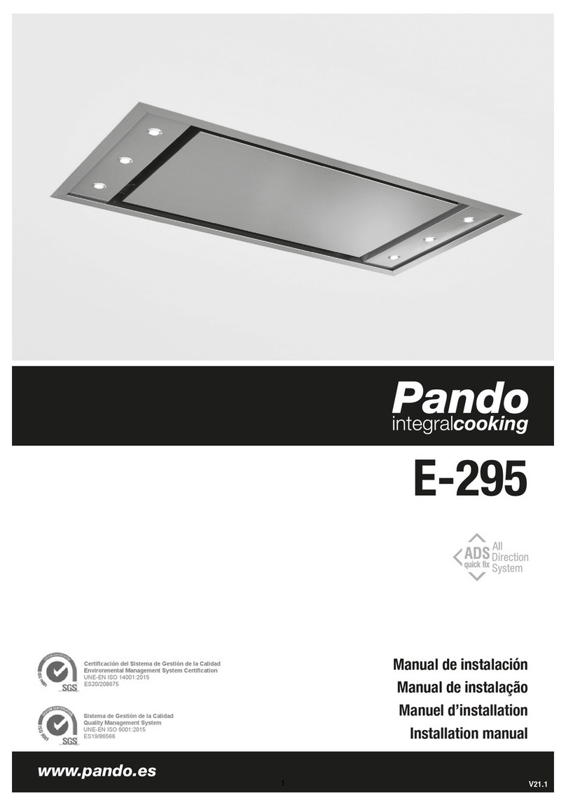
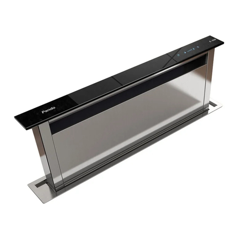
Pando E-220 User manual

HOOD
E-220
INSTALLATION GUIDE
660066400119


INSTALLATION MANUAL FOR MODEL E-220
page 2
1 – MINIMUM DIMENSIONS
THICKNESS OF FALSE CEILING
OUTLET RING COVER
To install this model in your kitchen it is necessary to take into account that the minimum distance
between the CEILING and the false ceiling should be 187 mm. Bearing in mind that the maximum
distance from the FLOOR to the FALSE CEILING should not be more than 2.50 m.
The included threaded rods allow a height adjustment of 187 to 340 mm.
The conduit must be Ø 150 mm, connecting to the exhaust conduit, it can be adapted to a
Ø150 mm circular rigid conduit or optionally it can be connected to a rectangular adaptor
measuring 100x180 mm to Ø150 mm round.
* As standard it comes with the outlet on the short side
** Optionally you can order it with the outlet on the long side. This can only be changed if
requested before leaving the factory, if it has already been delivered, it should be done
with the after sale service.
2 – AIR EXTRACTOR OUTLET

ANUAL DE INSTALACIÓN DE LA E-250, E-260, E-270 V1000
INSTALLATION MANUAL FOR MODEL E-220
It is recommended to install and connect the hood tubes before closing the false ceiling, if this
is not done, draw the perimeter of the perimeter of the fitting orifice of the hood on the ceiling
according to the type of outlet.
OUTLET ON SHORT SIDE OUTLET ON LONG SIDE
STANDARD
ORIFICE
FOR HOOD
ORIFICE
FOR SPECIAL
ORDER HOOD
*NOTE: 500 x 500 area reserved for connecting the hood tubes, close the false ceiling when installed
This model is supplied with threaded rods. These are screwed into the ceiling structure. Nuts are
used to adjust the height of the hood (187 mm – 340 mm).
Make 4 holes in the ceiling, according to the dimensions indicated in the drawing, insert the plugs
the hood into the holes and screw in the threaded rods.
page 3
3 – FITTING INTO THE CEILING

INSTALLATION MANUAL FOR MODEL E-220
page 4
CEILING STRUCTURE
HOOD SUPPORTS
FALSE CEILING
4 – PREPARING THE HOOD FOR INSTALLATION
Let the Ø150 extraction conduit drop down from the false ceiling (This conduit should be connected
to the extraction conduit of the premises equivalent to Ø150 mm) and leave it hanging about
If there is surplus flexible conduit (If on taking it out it projects more than 30 cm) the surplus should
be cut off and removed, so as to avoid undesired bends in the conduit installation.
Install the accessory supplied with the hood to convert the rectangular 100 x 180 section to Ø150.
And prepare the mains cable for connection.
WARNING! To avoid air leaks or the conduit detaching, make sure the joints of the conduit with
the adaptor are well sealed, once fitted, seal with adhesive aluminium tape or ties.
CONVERTER FROM RECTANGULAR
CROSS-SECTION TO Ø150
30 cm down.

ANUAL DE INSTALACIÓN DE LA E-250, E-260, E-270 V1000
INSTALLATION MANUAL FOR MODEL E-220
page 5
5 – RAISING THE HOOD, SECURING IT and CONNECTING TO THE POWER SUPPLY
Insert the hood in the orifice that has been cut ensuring that the threaded rods enter their holes.
The external edge of the hood should coincide perfectly with the false ceiling. Fit the washers
and nuts supplied with the hood to threaded rods, making sure they are properly tightened and
Wing nuts and washers, turn the wing nut until
you obtain the desired height, taking into
account that the bezel of the hood should be
flush with the false ceiling.
at the right height.

INSTALLATION MANUAL FOR MODEL E-220
page 6
Connect the rectangular to Ø 150 converter to the rectangular hood outlet, (It is a tight fit to
avoid leaks) and connect the hood to the MAINS.
WARNING! To avoid air leaks or the conduit detaching, seal the joint of the adaptor to the
hood, when fitted, seal well with adhesive aluminium tape.
without power until the installation is completely finished.
WARNING! Before connecting to the mains, make sure the socket is not live. It should be
Once it is connected, test in operation looking for air leaks, if everything is Ok, close the
500 x 500 false ceiling.
With the hatch open, you can see the on/off switch of the hood. (If all the connections have
been made) proceed to start it up.
WARNING! Once in operation, follow the instructions for synchronizing the remote control
on Page 8 (Before 15 seconds have passed press the light key on the remote control).
6- STARTING UP:

ANUAL DE INSTALACIÓN DE LA E-250, E-260, E-270 V1000
Enjoy your
INSTALLATION MANUAL FOR MODEL E-220
page 7
7 – FITTING THE FILTERS AND CLOSING THE HATCH:
Fit the filters in their position.
Close the hood hatch.
Follow the start up and operation
instructions.
Pando hood
THINGS TO TAKE INTO ACCOUNT:
* The ceiling the hood is to be fitted to should be completely flat and level.
* For correct operation of this model it is necessary to have ventilation grilles at floor level
for continuous admission of air.
* The maximum distance from the FLOOR to the FALSE CEILING must not be greater than
2.5 m.
**IMPORTANT: For optimum aspiration, the hood should be centred over the cooking
area.
ACCESSORIES INCLUDED: (The accessories are inside the hood)
4 Threaded 8 mm rods 8 Washers, Ø24mm
4 Washers, Ø60mm 4 Nuts, 8mm.
4 Wing nuts, 8mm. 4 Metal 8mm plugs
1 Remote control. 1 Instruction manual
1 100 x 180 to Ø150 adaptor 1 Installation manual.
2 Metres of 006744 tube, Spiral circular Ø150Tube (10m)

WARNING!!! –
*
{: OFF
:ON
OFF ON
page 8
First start of the hood.
Remote control synchronization.
Once installed the hood and the electrical connection to the main power, switch on the main power
switch in the connections box and we synchronize the remote control. The process is as follows:
Open the panel that covers the filter, extract the filter. It can see the connection box. On the side of
the box or just above, we can find the main power switch and start of the hood. Press the ON position
(see position junction box and switch on drawing, depending on the model or versions).
(Once started follow the synchronization instructions of the remote control)
Once put the switch in ON position and before 15 seconds, it should pressing or holding the
light button on the remote control facing the hood. Then the light will turn on the hood and it will
confirm that synchronization was successful.
Light button
Light button
The remote control synchronization with hood can be lost due to not making the synchronization
process well before 15 seconds after the switch on, due to power outages or variations on the
electrical network, causing the hood doesn't respond to remote control commands, so it must be
synchronize again.
* Synchronizing the remote control with the hood:
1 - Disconnect the house's main power or the connection box that feeds the hood (OFF).
2 - Reconnect the house's main power or the connection box that feeds the hood (ON).
3 - WARNING: Once the 2nd step was done, before within 15 seconds, face the remote control
the hood and press or hold down the command *LIGHT button.
4 - Then, head lights will light in the hood, so the code for the remote control has been
registered by the hood and is already synchronized.

page 9
Corian version remote control. User Instructions.
1. Hood motor on and off.
2. Reduce motor speed.
3. Increase motor speed.
4. Motor timer, keeps the hood on for 10 minutes and then switches it off.
5. Led indicator of control key pressed. Also indicates programming process.
6. Light on and off. *.
* A short press switches the main light on or off, and in models with a courtesy light, this is controlled with a long push,
keeping the key pressed for more than 2 seconds.
Synchronising the control with the hood:
When the hood is installed or if a change is made in the transmission code, it is necessary to synchronise the control with
the hood control unit. The process is as follows: Disconnect and then reconnect the power supply to the hood (with the
hood control unit switch or by unplugging the hood, or with the circuit breaker switch on the home electric panel), when
the hood has ben reconnected to the mains supply, before 20 seconds have passed press the light key with the remote
control pointing to the hood, the hood will light up, indicating that the process was correct.
If more than 20 seconds pass before you synchronise the control, the control unit will close the reception and no code will
be recorded.
Attention!: Synchronisation of the remote control with the hood can be lost due to external reasons such as power cuts,
electrical discharges, interference….In these cases it is necessary to repeat the synchronisation process.
Generating a new transmission code:
The manufacturer supplies the remote control ready for use, with the factory default codes.
If you want to generate new codes, do the following: Press simultaneously and keep pressed the three keys indicated in
the illustration (1-2-3) until the LED (5) begins to flash, at that moment the control is going through the different frequencies
available, when you release the keys, the led (5) will stop flashing and record the frequency being scanned at that
moment.
If you want a different frequency, repeat the process (after re-establishing the factory default configuration), and the
chosen frequency will depend on the time you keep the keys pressed.
ATTENTION! This operation will definitively delete the existing codes.
Re-establishing factory default configuration:
If you have changed the transmission code and want to recover the factory default code, do the following: Press
simultaneously and keep pressed the three keys indicated in the illustration (1-2-3) until the LED (5) is permanently lit, at that
moment, the control has re-established the factory default frequency.
ATTENTION! This operation will definitively delete the existing codes.
ATTENTION– WARNING – MAINTENANCE
The battery must be replaced every year in order to guarantee optimum range of the transmitter.
To replace an exhausted battery, remove the back cover quite, remove the battery with care so as no to damage or deform
the unit’s connection tabs, insert a new battery observing the indicated polarity.
Button type battery, Lithium model CR-2032 3V. Used batteries must be disposed of adequately.
Operating frequency 433.92 Mhz, 4096 combinations.
This product complies with R&TTE Directive 99/5/EC specifications.
12 3456

Fa ricado por INOXPAN S.L.
Pol. Ind. El Cros — Av. El Molí de les Mateves, 11
Apdo. Correos nº21
08310 ARGENTONA (Barcelona - Spain)
Tel. +34 93 757 94 11
Fax. +34 93 757 96 53
www.pando.es
Com.pand[email protected]
Certificado de Empresa de Gestión de la
Calidad UNE-EN ISO 9001:2008
The International Certification Network
Quality Management System ISO
9001:2008
Other manuals for E-220
1
Table of contents
Other Pando Ventilation Hood manuals

Pando
Pando I-1001 User manual

Pando
Pando UNE EN 60335-1 Operating manual

Pando
Pando E-250 User manual

Pando
Pando GR-05 User manual

Pando
Pando I-861 User manual

Pando
Pando P-2010 Operating manual

Pando
Pando V.3000 N ECO User manual

Pando
Pando I-898 User manual

Pando
Pando E-252 User manual

Pando
Pando I-437 Operating manual