Alere Triage MeterPro User manual

MeterPro User Manual
Alere Triage®


© 2017 Alere. All rights reserved 1
Table of Contents
Introduction
How to Use This Guide ....................2
Introduction .............................4
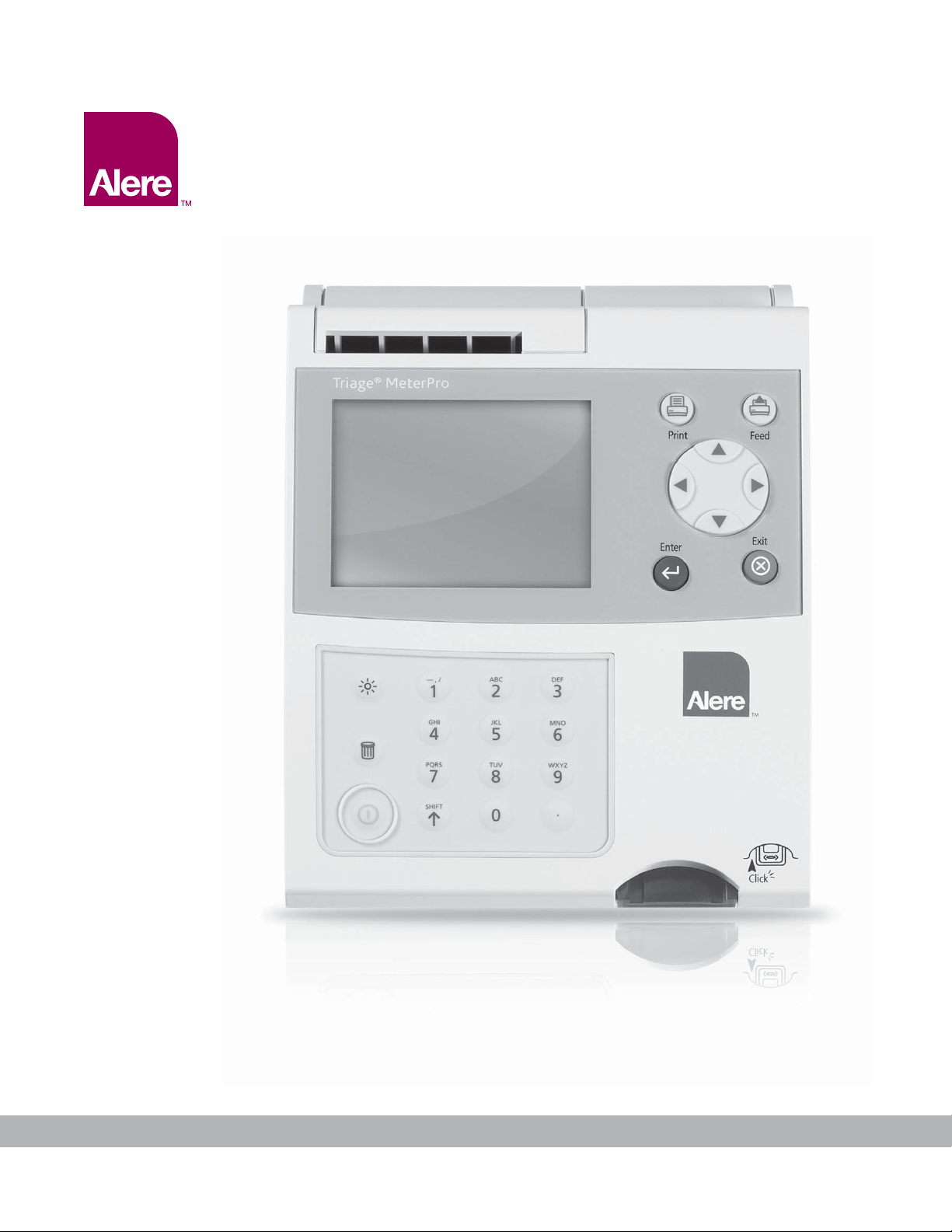
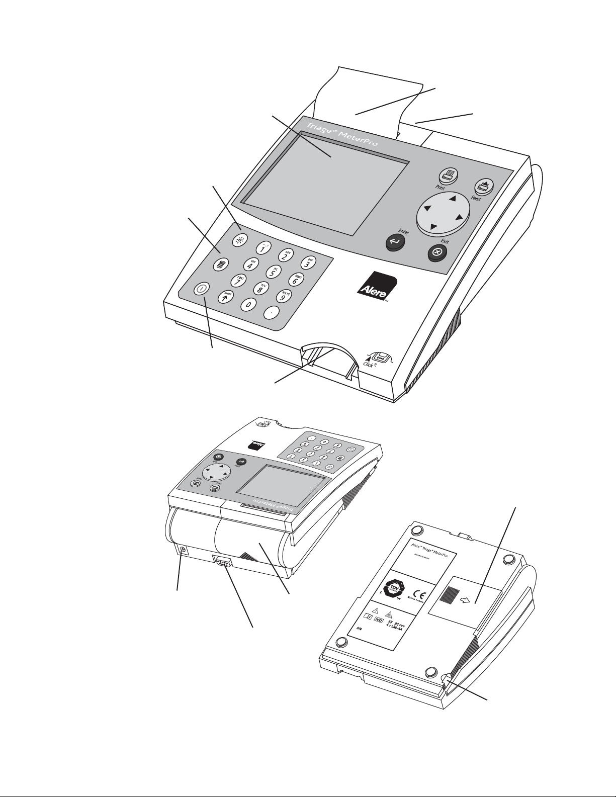
Description ...........................4
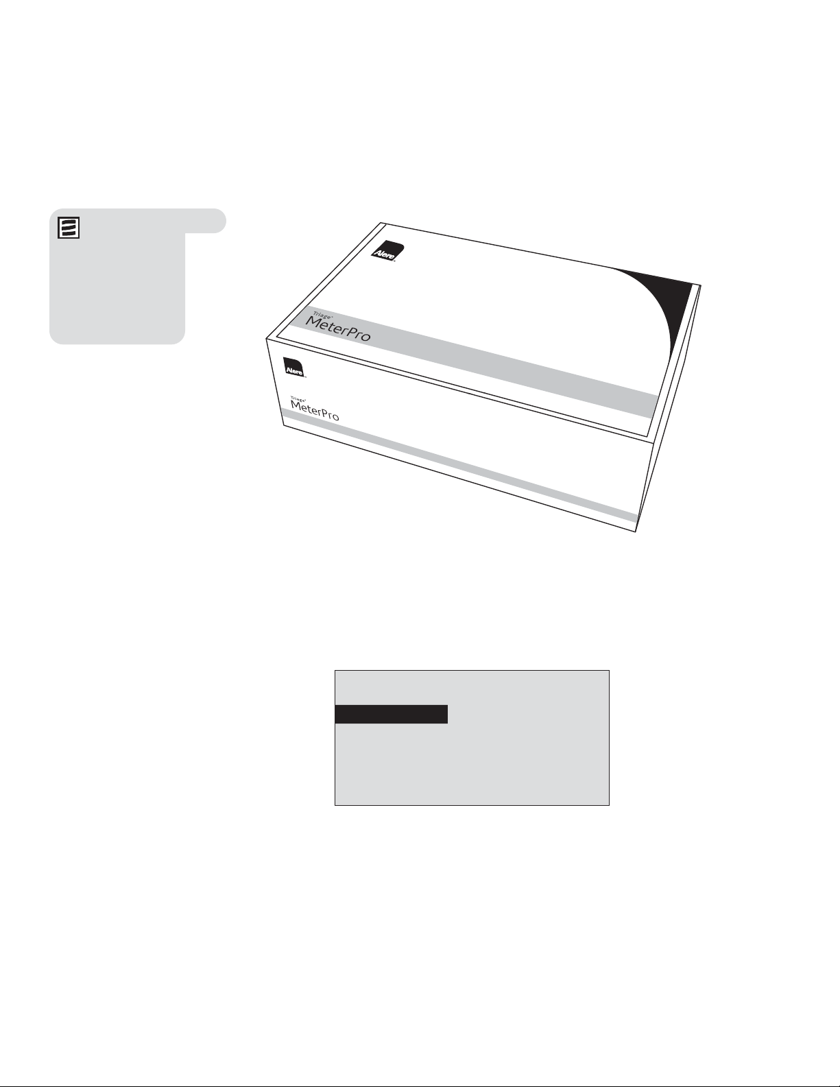
Unpacking ............................5
Specifications ...........................8
Test Device Specifications ...............8
Warnings, Precautions and Limitations .......9
Installation
Installation .............................11
Set Parameters .........................20
List of Programmable Parameters ........20
Supervisor Access ....................20
How to Set Parameters: Basic Instructions
....21
Meter Settings........................21
Communication Settings................28
Clock ...............................31
User ID .............................32
Ranges .............................35
Test Settings .........................36
QC Parameters .......................38
Bypass..............................39
Install CODE CHIP™module ...............40
Operation
Operation..............................42
Run Test ..............................43
Purpose .............................43
QC Device .........................44
QC Sample ........................46
Patient Sample .....................48
Misc. Test .........................51
Recall Results ..........................53
Last Record........................53
Patient Results .....................54
QC Results ........................61
Reagent Lots–QC ...............67
Archive Last Test................67
Misc. Test Results...................68
Print all Results .....................74
Delete Results ..........................76
Display Backlight........................78
Alpha Numeric Mode ....................79
Care & Maintenance
Total Quality Assurance ..................80
Service and Maintenance Procedures .......85
Troubleshooting ........................88
Return and Disposal Procedure ............91
Appendix
Glossary ..............................93
Software Flowchart ......................95
Labeling Symbols .......................96
Sample Log Sheets......................97
Contact Alere .........................100
Limited Warranty .......................101
Triage®
MeterPro User Manual

2© 2017 Alere. All rights reserved.
How to Use This Guide
This manual contains:
• Instructions for the operation and maintenance of the Alere Triage®MeterPro, and;
• Basic instructions for testing samples
The Alere Triage®MeterPro software has been designed to provide the user step by step
instructions. The meter displays test results and menu options in the upper half of the meter
screen. In smaller letters at the bottom of each screen, the meter displays instructions
pertaining to the task being performed.
8:23AM 01•20•11
RUN TEST
RECALL RESULTS
INSTALL NEW CODE CHIP
SELECT WITH v OR ^ AND PRESS ENTER
PRESS EXIT TO EJECT DEVICE
The display above is the Main Menu and appears
after the meter has been turned on and completed
an automatic self-test.
Note: To run
specific tests,
such as the Alere Triage®
Cardiac Panel, you
also will need detailed
information contained
in the product-specific
package insert, included in
the test kit.

© 2017 Alere. All rights reserved 3
The Alere Triage®MeterPro User Manual is divided into five sections.
Section 1 – Introduction: Provides an overview of Alere Triage®MeterPro.
Section 2 – Installation: Guides the user through first time setup.
Section 3 – Operation: Guides the user through running tests, recalling results and
deleting results.
Section 4 – Care & Maintenance: Total Quality Assurance, Warnings, Precautions
and Limitations, Service and Maintenance, Warranty.
Section 5 – Appendix: Troubleshooting, Sample Log Sheets, Index of Page Revisions,
Certificate of Conformity, Software Flowchart, Glossary
Symbols Meter Keys are indicated by
= Caution = Up key = Down key
= Important = Left key = Right key
= Note = On/Off key = Delete key
= Brightness key = Shift key
= Symbol key (used with Shift key)
= Print key = Paper Feed key
= Enter key = Exit key
Screen commands and options are indicated by a Bolded Font
.

4© 2017 Alere. All rights reserved.
Alere Triage®Test Devices. A test device
holds the sample and also contains the
reagents and other materials needed for
the test.
Introduction
Description
What is the Alere Triage®MeterPro?
The Alere Triage®MeterPro is a portable fluorescence instrument used to measure the
results of tests manufactured by Alere San Diego, Inc. The Alere Triage®MeterPro can be
used in a laboratory or in a point-of-care setting.
The Alere Triage®MeterPro uses a laser as a light source. Light from the laser hits a test
device that has been inserted in the meter. This causes the fluorescent dye in the test device
to give off energy. The more energy the fluorescent dye gives off, the stronger the signal.
Overview: Running a Test
After a test sample (for example, blood) from a patient is added to the test device, the test
device is inserted in the Alere Triage®MeterPro. The meter measures how much of the
substance (a particular protein marker) is present, based on standards that have been pre-
programmed into the meter. The patient identification, the User I.D. and the test results can
be printed out on a paper tape.

© 2017 Alere. All rights reserved 5
In addition to testing samples from patients, the Alere Triage®MeterPro contains pre-
programmed Quality Control (QC) functions that allow the person operating the meter to
monitor quality control.
Unpacking
The Alere Triage®MeterPro and the items that come with it are provided in a single box.
Alere Triage®test devices are packaged separately and include instructions for running
specific tests. If you have any questions, contact Alere (refer to the Contact Alere section).
Contents:
• Alere Triage®MeterPro
• QC Device & CODE CHIPTM module (in the QC Device box)
• AC / DC Power Converter
• AA Batteries
• Rolls of Printer Paper (additional rolls are supplied in each box of test devices)
• Supervisor CODE CHIPTM module & CODE CHIPTM module Box
Printer paper
located below
QC Device Box
Note: The Alere
Triage®MeterPro
accepts test devices that
are designed specifically
for use with the Alere
Triage®MeterPro. Please
refer to product-specific
package inserts included
in each test kit for more
information.

6© 2017 Alere. All rights reserved.
Parts of the Alere Triage®MeterPro
Power button
Delete
Backlight
Test device insertion port
Thermal Printer
Data port
Battery cover
Power supply port
LCD (liquid crystal display) Printer cover
Printer cover
CODE CHIPTM module port

© 2017 Alere. All rights reserved 7
Power button Used to turn the Alere Triage®MeterPro on and off.
Print Button Used to print the test results or display screen.
Delete Button Used to delete data.
Enter Button Allows the operator to select menu items and acknowledge
alarm conditions.
Exit button Used to exit the displayed menu or eject the test device.
Keypad Used to enter identification numbers, letters, and special symbols.
Arrow Buttons Used to toggle through menu items.
Thermal Printer Prints the test result on paper.
Data Port Connection point for the (optional) Bar Code Scanner,
allowing the operator to scan patient or user identification
data instead of manually entering numbers or letters on the
keypad. May also be used to connect to a data management
system/LIS.
CODE CHIPTM module Port Insertion point for CODE CHIPTM modules which contain lot /
device specific data for use in providing test results.
Power Supply Port Connection point for the supplied AC / DC Power Converter.
Printer Cover The cover, which when pulled straight up, reveals the paper roll.
LCD Screen The LCD (Liquid Crystal Display) Screen shows the menu of
possible tests and tasks and prompts the operator to take the
next step.

8© 2017 Alere. All rights reserved.
Specifications
Physical
Size 8.5” x 6.25 “x 2.75” (22.5 cm x 19 cm x 7 cm) D x W x H
Weight 1.5 pounds (0.7 kg) without batteries
Electrical
6v DC at 1 amp – supplied via 4 AA batteries or AC/DC Converter
Keypad Numeric with special function keys (22 total)
Environmental
Temperature 15°C – 30°C
Humidity 10% – 85%
Location Dry, clean, flat horizontal surface away from direct sunlight
Optical
Light Source Laser Diode – <1 milliwatt
Laser Classification 1
Detector Silicone Photodiode
Memory Capacity
750 Patient Records 32 Reagent Lot CODE CHIPTM modules
200 QC Sample Results 200 QC Sample CODE CHIPTM modules
70 QC Device Results 4 QC Device CODE CHIPTM modules
250 Misc Test Results
600 User ID’s
Miscellaneous
RS-232 computer interface port
Thermal Printer
LCD screen display
Options
• External Bar Code Reader (rapid entry of User, Patient, Auxiliary or Misc Test ID’s).
• Alere Triage Census®Data Management Software.
• Alere Triage Census®Data Management Software with LIS Connectivity.
Test Device Specifications
Test device specific information is provided in the applicable product insert. The
instrument analyzes immunoassay test devices manufactured by Alere San Diego, Inc.

© 2017 Alere. All rights reserved 9
• The Alere Triage®MeterPro must be used within the operating temperature range
required by the specific test device product being used. Refer to the test device
package insert for details.
• Operate the Alere Triage®MeterPro on a level, dry surface away from direct sunlight.
• The QC Device is light-sensitive and should be stored in its black opaque case
when not in use.
• Do NOT write or place a label anywhere on the QC device, as it may interfere with
the device functionality.
• Do not move the Alere Triage®MeterPro while a test is in progress.
• Ensure all sample fluids have absorbed into the test device prior to running the test
to prevent internal contamination of the meter.
• Use only the AC/DC power adapter provided with the Alere Triage®MeterPro. An
identifying tag has been placed on the cord for quick identification.
• Do not drop the Alere Triage®MeterPro.
• Do not place objects on the Alere Triage®MeterPro.
• Do not immerse the Alere Triage®MeterPro in water or any liquids.
Warnings, Precautions and Limitations

10 © 2017 Alere. All rights reserved.
(Intentionally blank)

© 2017 Alere. All rights reserved 11
The Main Menu
1. Unpack Meter:
a. Remove the meter from the box and protective plastic bag.
2. Power Meter On:
Batteries
a. Turn the meter over.
b. Remove battery cover.
c. Install 4 AA batteries, paying attention to battery orientation in the battery
compartment.
d. Replace battery cover and turn meter right side up.
e. Power the meter on by pressing the key. Press the key to run self-test.
When the test is completed, the meter display screen will come to rest at the
main menu.
8:23AM 01•20•11
RUN TEST
RECALL RESULTS
INSTALL NEW CODE CHIP
SELECT WITH v OR ^ AND PRESS ENTER
PRESS EXIT TO EJECT DEVICE
AC Power Supply
a. Remove the power supply from the box.
b. Plug one end into an AC outlet.
c. Plug the opposite end into the round hole in the back of the meter.
Installation
User instructions
Low Power Indicator
Menu items
Time and date
Note: The Low
Power Indicator
monitors the active
power source. To verify
adequate battery power:
• Navigate to the Main
Menu
• Remove the AC power
supply
• Press the
EXIT key (the
meter attempts to eject
a device)
• Observe the Main Menu
on the meter’s display.
Replace the batteries if
the power icon is visible.

12 © 2017 Alere. All rights reserved.
3. Install paper:
a. Remove the printer cover by pulling up on the cover as indicated by the arrow on
the back of the cover.
b. Tear or cut a clean, straight edge to feed into the printer. Do not cut paper at an
angle, as the printer must sense the edge of the paper along the feed path.
c. Position the paper such that the paper will feed from under the roll (as opposed to
over the top of the roll, see picture).
d. Insert the paper edge under the paper roller (platen) until it firmly seats or resistance
is felt.
e. Press the key twice, paper will feed through the printer and extend
out the meter.
f. Place the roll of paper into the paper compartment.
g. Replace the printer cover and continue operation.
Note: The printer
contains a paper
sensor and will feed the
new paper roll only when
paper with a clean straight
line is pressed into the
paper roller.
For more details about
Installing Paper see the
CARE & MAINTENANCE
section.

© 2017 Alere. All rights reserved 13
The Supervisor’s Main Menu
4. Insert Supervisor Code Chip module:
a. Remove the Supervisor CODE CHIPTM module Box from the meter box.
b. Remove the Supervisor CODE CHIPTM module from its box.
c. Insert the Supervisor CODE CHIPTM module into the CODE CHIPTM module Port. The
port is located on the left side of the meter, towards the bottom front corner. Note
the orientation of the CODE CHIPTM module in the drawing below.
d. Once the Supervisor CODE CHIPTM module is installed, verify that two additional
menu items appear on the display screen.
8:23AM 01•20•11
RUN TEST
RECALL RESULTS
INSTALL NEW CODE CHIP
SET PARAMETERS
DELETE RESULTS
SELECT WITH v OR ^ AND PRESS ENTER
PRESS EXIT TO EJECT DEVICE
For more details about
CODE CHIPTM modules
see page 19.
CODE CHIPTM module
CODE CHIPTM module port
Two additional menu
options accessible
when Supervisor
CODE CHIPTM module
is inserted.

14 © 2017 Alere. All rights reserved.
For reference, record your settings in the space provided.
For more details about
Meter Settings see
page 21.
5. To Change Meter Settings:
a. Select Set Parameters using the keys and press the key.
b. Select Meter Settings using the keys and press the key.
c. Select ID Settings, Display Settings or Comm Settings using
the keys and press the key.
d. Select the desired setting using the keys and change the value of the
setting by using the keys.
ID Settings Default Options New Settings
Characters User ID Min 1
Max 16
1-16
1-16
Characters Pat. ID Min 1
Max 20
1-20
1-20
Characters Aux ID Min 1
Max 12
1-12
1-12
Characters Misc ID Min 1
Max 20
1-20
1-20
Aux. ID Enable/Disable Disabled Disabled, Enabled
e. Press the key to save changes to ID Settings.

© 2017 Alere. All rights reserved 15
Display Settings Default Options New Settings
Language English
English, French,
Italian, German,
Spanish,
Portuguese, Greek,
Danish, Swedish,
Japanese
Print Mode Automatic Automatic, Manual
Auto Power-Off 2 hour 1/2 hour, 1 hour, 2
hour, 4 hour, None
Display Contrast 4
0-8
(8=heaviest
contrast)
Printer Contrast 4
0-8
(8=heaviest
contrast)
f. Press the key to save changes to Display Settings.
COMM Settings Default Options New Settings
Baud Rate 38400 9600, 38400
Pat. Result Approval Disabled Enabled, Disabled
LIS Enable/Disable Disabled Disabled, Enabled
Auto Upload Disabled Disabled, Enabled
LIS Password
g. Press the key to save changes to Communication Settings.
h. Press the key to save changes to Meter Settings.
For reference, record your settings in the space provided.
For more details about
Communications, including
entry of an Alere provided,
meter specific password,
see page 28.

16 © 2017 Alere. All rights reserved.
6. Change Clock:
a. Select Set Parameters using the keys and press the key.
b. Select Clock using the keys and press the key.
c. Select the Hour : Minute area using the keys. Type in the correct time
using the number keys.
d. Press the key to move to AM or PM.
e. Select AM or PM using the keys.
f. Press the key to move to Time Format.
g. Select AM/PM or 24 HR. using the keys. If selecting 24 HR.,
the previously entered Hour : Minute will change to a 24-hour format and
the AM or PM will disappear.
h. Press the key to move to the Date.
i. Type in the 6-digit date according to the Date Format below it.
j. Press the key to move to the Date Format.
k. Select MM-DD-YY, DD-MM-YY or YY-MM-DD using the keys.
The previously entered Date changes as the Date Format changes.
l. Press the key to save changes.
Setting Default Options New Settings
Time Format AM / PM AM / PM; 24HR
Date Format MM-DD-YY
MM-DD-YY,
DD.MM.YY,
YY-MM-DD
7. Set User ID:
The Alere Triage®MeterPro normally requires a User ID to be entered prior to running
a patient test, QC test, or Misc test, and prior to recalling patient results. Refer to page
32 for instructions. Alternately, this feature may be bypassed. See page 18.
For more details about
Clock Settings see
page 31.

© 2017 Alere. All rights reserved 17
For more details about
Ranges Settings see
page 35.
For more details about
Test
Settings
see page 36.
Note: The lowest
value of the Range
or Threshold may be
disabled for some test
panels. Refer to the
appropriate Product Insert
for specific information.
8. Change Reference Ranges / Thresholds for Tests:
a. Select Set Parameters using the keys and press the key.
b. Select Ranges using the keys and press the key.
c. Select the test panel type using the keys.
d. Select the analyte and level using the keys. Type in the new value for
the High or Low cutoff as appropriate.
e. Press the key to save changes.
9. Change Test Settings:
a. Select Set Parameters using the keys and press the key.
b. Select Test Settings using the keys and press the key.
c. Select the test panel type using the keys.
d. Select the analyte using the keys.
e. Select the test setting (ACTIV, INACT, USR A, or USR I) using the keys.
f. Press the key to save changes.
10. Change QC Parameters:
a. Select Set Parameters using the keys and press the key.
b. Select QC Parameters using the keys and press the key.
c. Select the desired setting using the keys and change
the value to the right of the setting by using the keys.
Setting Default Options New Settings
QC Device Freq. Daily None, 8HR, Daily,
Weekly, Monthly
QC Sample Freq. Monthly None, 8HR, Daily,
Weekly, Monthly
Number of Controls 2 1 or 2
Num Quant Std Devs 3 2 or 3
d. Press the key to save changes to QC Parameters.
Note: The ability
to change test
settings may be disabled
for some tests in specific
panels. Refer to the
appropriate Product Insert
for specific information.
For more details about QC
Parameters Settings see
page 38.

18 © 2017 Alere. All rights reserved.
11. Change Bypass settings:
a. Select Set Parameters using the keys and press the key.
b. Select Bypass using the keys and press the key.
c. For User ID select On or Off using the keys.
d. Press the key to save changes to the Bypass setting.
12. Prior to commencing patient testing, remove the Supervisor CODE
CHIPTM module from the meter, return it to the storage box and place
in a safe place for future use.
The meter is now ready to run QC Tests in preparation for Patient Testing.
QC Testing should be performed in the following manner:
1. Run QC Device (see page 44).
2. Run QC Sample for each lot of devices (see page 46).
3. If appropriate, run Calibration Verification Set as a Misc Test sample for each test
panel type to be used. (Refer to the applicable Procedure Manual and Calibration
Verification Set Package Insert for detailed instructions).
Location
The Alere Triage®MeterPro should be placed on a dry, clean, flat, horizontal surface away
from direct sunlight.
Power
The Alere Triage®MeterPro requires 6-volts DC supplied by either AC or DC. The meter
will run approximately 100 tests on batteries. It is recommended to use batteries as a
backup in the event of a power outage.
Caution: Use only the power supply provided with the meter, failure to do
so may cause permanent damage to the meter.
For more details about
Bypass Settings see
page 39.
Note: If the
bypass is ON, the
user ID feature is disabled
and anyone may run a
test. If the bypass is OFF,
the user ID feature is
active and only authorized
users may run a test.
To Install User ID’s, see
page 32.
Note: The Alere
Triage®MeterPro
will automatically turn off
if left unused for 2 hours,
unless programmed
otherwise by the
supervisor. Optional
settings allow automated
turnoff after 1
/2hour,
1 hour, 2 hours, 4 hours
or NONE.
Table of contents
Other Alere Measuring Instrument manuals
Popular Measuring Instrument manuals by other brands

brown & sharpe
brown & sharpe Global 9128 user manual

multicomp pro
multicomp pro MP780905 user manual

Grizzly
Grizzly H5844 instruction sheet

Precision Digital Corporation
Precision Digital Corporation Vantageview PD6730 manual

Knick
Knick Stratos Eco 2405 Oxy quick start

Proteus
Proteus ATEX Zone 1 Original User Instruction Manual