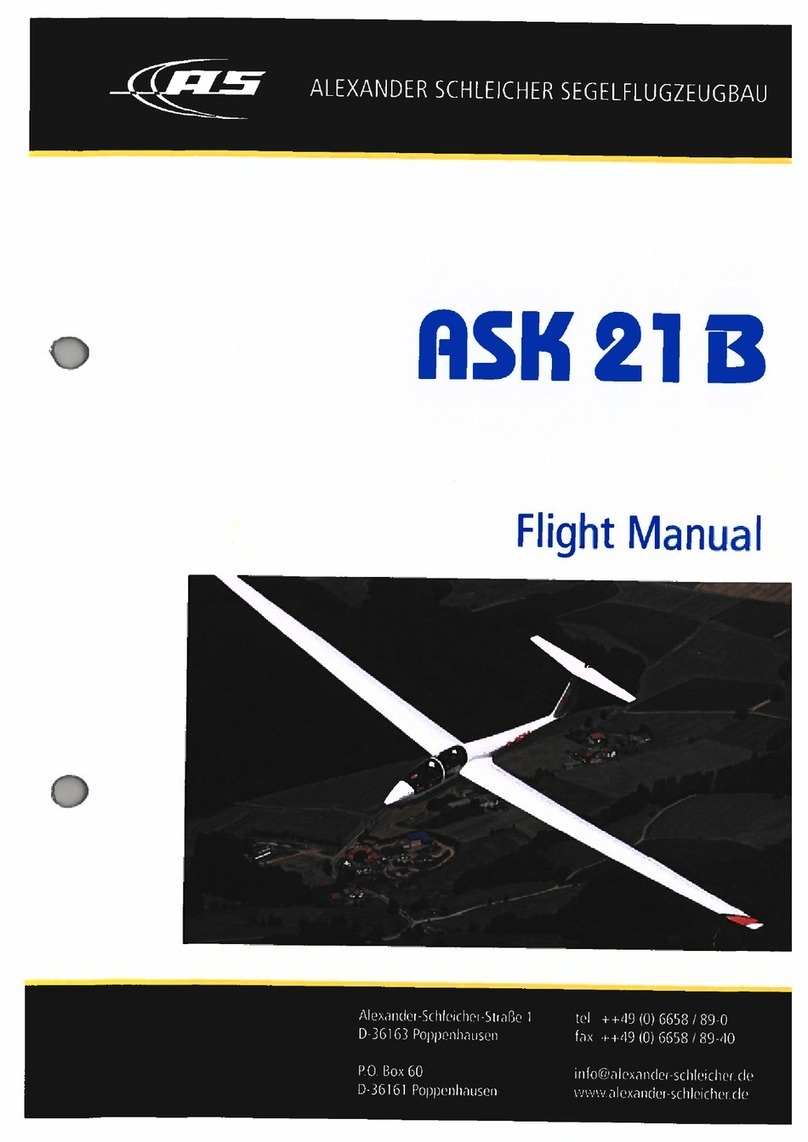
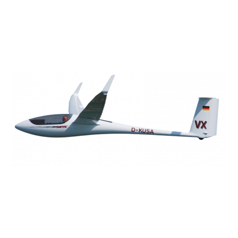
Alexander Schleicher ASK 21 B User manual

ALEXANDER
SCHLEICHER
SEGELFLUGZEUGBAU
ASK
21
Maintenance
Manual
Repair
Manual
4
•
40
—
Alexander-Schleicher-StraBe
1
D-36163
Poppenhausen
P.O.
Box
60
D-36161
Poppenhausen
tel
++49
(0)
6658
/
89-0
fax
++49
(0)
6658
/
89-40
info@alexander-schleichende
www.alexander-schleicher.de

Alexander
Schleicher
GmbH
&
Co.
Segelflugzeugbau
D-36163
Poppenhausen/Wasserkuppe
Maintenance
Manual
for
the
sailplane
ASK
21
B
Model:
ASK
21
B
Serial
Number:
21953
Registration:
VH-GTY
Data
Sheet
No.:
EASA.A.221
Issue:
15.06.2018
The
translation
has
been
done
by
best
knowledge
and
judg-
ment.
In
any
case
the
original
text
in
German
is
authoritative.

Maintenance
Manual
ASK
21
B
Maintenance
Manual
Section
0
Copyright
©
2018
Alexander
Schleicher
GmbH
&
Co.
Poppenhausen/Wasserkuppe
All
rights
reserved.
Reprint
or
copying
-also
partially-
only
with
the
au-
thor's
permission.
0.1
Record
of
Revisions
Any
revision
of
the
present
manual,
except
actual
weighing
data,
must
be
recorded
in
the
following
table
"Record
of
Revisions".
The
new
or
amended
text
in
the
revised
page
will
be
indicated
by
a
black
vertical
line
in
the
left
hand
margin,
and
the
Revision
No.
and
the
date
will
be
shown
on
the
bottom
of
the
page.
Issue:
15.06.2018
MM,
PA
Revision:
0.1

Maintenance
Manual
ASK
21
B
Maintenance
Manual
Record
of
Revisions
Rev
No.
Section
&
Pages
Affected
Date
of
Issue
Date
of
Insertion
Ref.
/
Signature
Issue:
15.06.2018
MM,
PA
Revision:
0.2
TN 6
2.2.4 Rudder, 2.4
5/6/23
4/11/20
TN 9
7.1 Periodic Inspections, 7.5
5/5/22
5/6/23
GG,22990
GG,22990

Maintenance
Manual
ASK
21
B
Maintenance
Manual
Record
of
Revisions
Rev
No.
Section
&
Pages
Affected
Date
of
Issue
Date
of
Insertion
Ref.
/
Signature
Issue:
15.06.2018
MM,
PA
Revision:
0.3

Maintenance
Manual
ASK
21
B
Maintenance
Manual
0.2
List
of
Effective
Pages
Section
Page
Date
Section
Page
Date
title
page
15.06.2018
2.23
15.06.2018
2.24
15.06.2018
0
0.1
15.06.2018
2.25
15.06.2018
0.2
15.06.2018
2.26
15.06.2018
0.3
15.06.2018
2.27
15.06.2018
0.4
15.06.2018
2.28
15.06.2018
0.5
15.06.2018
2.29
15.06.2018
0.6
15.06.2018
2.30
15.06.2018
2.31
15.06.2018
1
1.1
15.06.2018
1.2
15.06.2018
3
3.1
15.06.2018
1.3
15.06.2018
3.2
15.06.2018
1.4
15.06.2018
3.3
15.06.2018
1.5
15.06.2018
3.4
15.06.2018
3.5
15.06.2018
2
2.1
15.06.2018
2.2
15.06.2018
4
4.1
15.06.2018
2.3
15.06.2018
4.2
15.06.2018
2.4
15.06.2018
4.3
15.06.2018
2.5
15.06.2018
4.4
15.06.2018
2.6
15.06.2018
4.5
15.06.2018
2.7
15.06.2018
4.6
15.06.2018
2.8
15.06.2018
4.7
15.06.2018
2.9
15.06.2018
2.10
15.06.2018
5
5.1
15.06.2018
2.11
15.06.2018
5.2
15.06.2018
2.12 15.06.2018
5.3
15.06.2018
2.13
15.06.2018
5.4
15.06.2018
2.14
15.06.2018
5.5
15.06.2018
2.15
15.06.2018
2.16
15.06.2018
6
6.1
15.06.2018
2.17
15.06.2018
6.2
15.06.2018
2.18
15.06.2018
6.3
15.06.2018
2.19
15.06.2018
6.4
15.06.2018
2.20
15.06.2018
6.5
15.06.2018
2.21
15.06.2018
6.6
15.06.2018
2.22
15.06.2018
6.7
15.06.2018
Issue:
15.06.2018
MM,
PA
Revision:
0.4

Maintenance
Manual
ASK
21
B
Maintenance
Manual
6.8
15.06.2018
6.9
15.06.2018
6.10
15.06.2018
6.11
15.06.2018
6.12
15.06.2018
6.13
15.06.2018
6.14 15.06.2018
7
7.1
15.06.2018
7.2
15.06.2018
7.3
15.06.2018
7.4
15.06.2018
7.5
15.06.2018
7.6
15.06.2018
7.7
15.06.2018
7.8
15.06.2018
8
8.1
15.06.2018
8.2
15.06.2018
8.3
15.06.2018
8.4
15.06.2018
9
9.1
15.06.2018
9.2
15.06.2018
9.3
15.06.2018
9.4
15.06.2018
9.5
15.06.2018
9.6
15.06.2018
9.7
15.06.2018
9.8
15.06.2018
9.9
15.06.2018
9.10
15.06.2018
10
10.1
15.06.2018
10.2
15.06.2018
10.3
15.06.2018
10.4
01.04.2017
10.5
01.04.2017
11
11.1
15.06.2018
11.2
15.06.2018
12
12.1
15.06.2018
12.2
15.06.2018
12.3
15.06.2018
12.4
15.06.2018
12.5
15.06.2018
12.6
15.06.2018
13
13.1
15.06.2018
13.2
15.06.2018
13.3
15.06.2018
13.4
15.06.2018
Issue:
15.06.2018
MM,
PA
Revision:
0.5

Maintenance
Manual
ASK
21
B
Maintenance
Manual
0.3
Table
of
Contents
Section
0
Record
of
Revision,
List
of
Effective
Pages,
Table
of
Contents
1
Description
and
Specifications
2
Description
of
Control
Systems
and
Equipment
ANN.
3
Deflections
of
Control
Surfaces
and
Flaps
4
Airworthiness
Limitations
5
Control
Surface
Masses
and
Tail
-heavy
Moments
6
Mass
(Weight)
and
Balance
7
Periodic
Inspections
and
Service
Life
Limitations
8
Lubrication
Scheme
9
Placards,
Labels
and
Markings
10
Repairs,
Removal
and
Re
-assembly
of
Components,
Tightening
Torques
11
Modification
of
the
Sailplane
12
Appendix
13
Supplements
Issue:
15.06.2018
MM,
PA
Revision:
0.6

Maintenance
Manual
ASK
21
B
Maintenance
Manual
Section
1
1
Description
and
Specifications
1.1
Introduction
1.2
Description
of
the
Sailplane
1.2.1
Wings
1.2.2
Fuselage
1.2.3
Tail
Unit
and
Aileron
1.2.4
Power
Plant
1.3
Primary
and
Secondary
Structures
1.4
Technical
Specifications
1.5
Three
View
Drawing
Issue:
15.06.2018
MM,
PA
Revision:
1.1

Maintenance
Manual
ASK
21
B
Maintenance
Manual
1
Description
and
Specifications
1.1
Introduction
This
Maintenance
Manual
was
produced
because
the
safety
and
air-
worthiness
of
an
aircraft
depends
on
the
careful
maintenance
of
all
its
components.
The
airworthiness
of
the
ASK
21
B
can
only
be
assured,
if
the
glider
is
maintained
and
operated
according
to
the
manuals.
The
maintenance
and
inspection
requirements
issued
by
the
Civil
Aviation
Au-
thority
of
the
country,
in
which
the
aircraft
is
registered,
must
be
observed.
Metric
units
of
measurement
are
used
for
this
manual,
while
for
the
Eng-
lish
issue
imperial
units
are
shown
in
parenthesis.
1.2
Description
of
the
Sailplane
The
ASK
21
B
is
a
mid
-wing
two-seater
glider
with
damped
T
-tail,
sprung
landing
gear
with
hydraulic
disc
brake
and
nose
wheel.
The
wing
is
equipped
with
air
brakes
on
the
upper
surface.
The
aircraft
is
built
in
GRP-sandwich-monocoque
construction.
It
may
be
used
for
school
and
performance
flights
as
well
as
for
aerobatics
of
the
airworthiness
category
"A".
1.2.1
Wings
The
glider
has
a
2
-part
wing
with
GRP/hard
foam
sandwich
surface.
The
I
-section
-spar
consists
of
glass
fiber
caps
wit
GRP/hard
foam
web.
The
wings
are
assembled
in
the
fuselage
by
means
of
a
tongue
-and
-fork
joint
and
two
cylindrical
main
pins.
The
fuselage
and
wing
connection
uses
four
drag
pins
at
the
fuselage
-side.
The
rear
drag
pins
are
connected
to
the
wings
by
means
of
socket
pins
so
they
are
also
able
to
take
up
tension
loads.
1.2.2
Fuselage
The
fuselage
and
fin
sandwich
shell
employs
GRP
with
a
honeycomb
core.
This
provides
a
light
and
rigid
structure
capable
of
protecting
the
pilot
even
in
the
case
of
an
accident.
Additionally
the
canopy
frame
is
enforced.
The
VHF
radio
aerial
is
located
in
the
fin.
Issue:
15.06.2018
PA
Revision:
1.2

Maintenance
Manual
ASK
21
B
Maintenance
Manual
1.2.3
Tail
Unit
and
Aileron
The
stabilizer
of
the
horizontal
T
-tail
unit,
the
elevator,
the
rudder
and
the
ailerons
consist
of
a
GRP/hard
foam
sandwich
construction.
1.3
Primary
and
Secondary
Structures
Primary
structure
includes:
-
wing
spars
and
root
ribs
-
wing
shells
WM,
fuselage
tail
boom
from
wing
mounting
area
to
fin
-
fin
and
horizontal
stabilizer
-
all
rigging
fittings
and
control
linkage
parts
Secondary
structure
includes:
-
control
surfaces
and
airbrakes
-
fuselage
in
the
cockpit
area
-
all
fairings
and
engine
bay
doors
1.4
Technical
Specifications
Wing
Span
17
m
(55.77
ft
)
Wing
area
17.95
m
2
(193.21
ft
2
)
Aspect
ratio
16.1
Dihedral
(wing
center
line)
4°
Sweepback
(inner
wing
leading
edge)
0°
Airfoils
Fuselage
FX
SO2
196
/
FX
60-196
Length
8.35
m
(27.39
ft
)
Height
at
the
T
-tail
incl.
tail
wheel
1.527
m
(5.01
ft
)
Cockpit
width
(outer)
0.7
m
(2.30
ft
)
Cockpit
height
(outer)
1.04
m
(3.41
ft
)
Vertical
tail
Height
above
tail
boom
center
line
1.37
m
(4.49
ft
)
Area
1.357
m
2
(14.61
ft
2
)
Aspect
ratio
1.383
Chord
(bottom
/
top)
1.17
m
/
0.8
m
Issue:
15.06.2018
MM,
PA
Revision:
1.3

Maintenance
Manual
ASK
21
B
Maintenance
Manual
Airfoil
Rudder
3.84ft/
2.62
ft
FX
71-L-150/30
Chord
ratio
31
%
Area
0.42
m
2
(4.52
ft
2
)
Horizontal
tail
Span
3.1
m
(10.17ft)
Area
1.92
m
2
(20.67
ft
2
)
Aspect
ratio
5.005
Airfoil
FX
71-L-150/30
Elevator
Chord
ratio
30
%
Area
0.576
m
2
(6.20
ft
2
)
Airbrakes
(Schempp-Hirth,
only
upper
surface)
Length
1.36
m
(4.46
ft
)
Area
(both
sides)
approx.
0.326
m
2
(3.51
ft
2
)
Masses
(Weight)
Empty
mass
(minimum
equipment)
approx.
375
kg
max.
mass
non
-lifting
parts
410
kg
max.
mass
in
a
seat
130
kg
max.
mass
in
baggage
compartment
10
kg
max.
take
-off
mass
600
kg
max.
wing
loading
33.4
kg/m
2
min.
wing
loading
(single
seated)
ca.
26
kg/m
2
(827
Ibs)
(904
Ibs)
(286
Ibs)
(22
Ibs)
(1323
Ibs)
(6.84
lbs/ft
2
)
(5.33
lbs/ft
2
)
See
also
Flight
Manual
section
2.
Authoritative
information
about
empty
mass
and
useful
load
are
docu-
mented
in
the
latest
weighing
record
or
in
the
mass
and
balance
form
in
chapter
6.2
of
the
flight
manual.
Issue:
15.06.2018
PA
Revision:
1.4

Maintenance
Manual
ASK
21
B
Maintenance
Manual
1.5
Three
View
Drawing
II.
Issue:
15.06.2018
MM,
PA
Revision:
1.5

Maintenance
Manual
ASK
21
B
Maintenance
Manual
Section
2
2
Description
of
Control
Systems
and
Equipment
2.1
Introduction
2.2
Control
Systems
2.2.1
Elevator
Control
System
2.2.2
Elevator
Trim
System
2.2.3
Aileron
Control
System
2.2.4
Rudder
2.2.5
Airbrake
Control
System
2.3
Landing
Gear
2.3.1
Wheels
and
Tires
2.3.2
Wheel
Brake
System
2.3.3
Maintenance
of
Landing
Gear
and
Wheel
Brake
2.4
Radio
Installation
2.5
Electrical
System
2.6
Oxygen
Installation
2.7
Pitot
and
Static
Pressure
System
and
Instrument
Connections
2.8
Jacking
Points
and
Ground
Transport
2.9
Tow
Releases
2.10
Additional
Equipment
and
Installations
Issue:
15.06.2018
MM,
PA
Revision:
2.1

Maintenance
Manual
ASK
21
B
Maintenance
Manual
2
Description
of
Control
Systems
and
Equipment
2.1
Introduction
Except
for
the
rudder,
all
other
control
surfaces
and
flaps
are
actuated
by
means
of
push
rods.
Some
of
the
bell
cranks
and
the
short
push
rods
are
of
welded
steel
construction.
The
long
push
rods
are
made
of
aluminium
tube,
with
steel
fittings
riveted
into
the
ends.
These
aluminium
push
rods
are
corrosion
resistant
and,
therefore,
they
are
not
surface
treated.
The
remaining
bell
cranks
are
milled
from
sheet
aluminium.
All
push
rods
are
supported
in
linear
ball
race
guides.
Where
required,
rubber
bellows
are
fitted
to
form
a
seal
where
push
rods
pass
through
wing
ribs.
NOTE
Additional
sealing
to
the
wing
root
ribs
is
not
allowed,
as
the
wing
will
be
no
more
ventilated!
2.2
Control
Systems
2.2.1
Elevator
Control
System
The
control
columns
are
two
-arm
levers
and
each
mounted
on
a
universal
joint.
A
steel
torsion
tube
(control
tube)
connects
both
control
columns
at
their
lower
ends.
This
control
tube
provides
the
adjustable
stops
for
the
elevator
control
system
on
its
front
and
rear
end.
A
second,
stepped
con-
trol
tube
leads
from
the
rear
control
column
above
the
main
wheel
to
a
vertical
rocker
lever,
mounted
on
a
universal
joint.
A
push
rod
extends
from
the
vertical
rocker
lever
to
drive
a
180°
Dural
bell
crank,
located
at
a
platform
at
the
fuselage
bottom
behind
the
wing
intersection.
An
aluminium
push
rod
leads
on
the
left
fuselage
side
from
the
180°
Dural
bell
crank
to
the
fin
and
is
supported
by
4
ball
bearing
longitudinal
guides.
Via
a
90°
Dural
bell
crank
and
a
FRP
plastic
rod
the
movements
are
trans-
mitted
to
the
top
of
the
fin.
There
another
push
rod
is
connected
via
a
180°
Dural
bell
crank,
the
upper
end
of
this
push
rod
forms
the
elevator
actuator.
Issue:
15.06.2018
MM,
PA
Revision:
2.2

Maintenance
Manual
ASK
21
B
Maintenance
Manual
2.2.2
Elevator
Trim
System
The
spring
trimmer
consists
of
2
trim
levers,
a
connection
rod
and
the
two
trim
springs
with
adjusting
plate.
The
trim
levers
are
mounted
coaxial
to
the
control
columns.
A
friction
brake
is
tightened
by
using
a
knurled
nut
onto
the
control
column
mounting
screw.
The
brake
force
should
be
adjusted
nearly
equally
for
the
front
and
rear
brake.
The
brakes
have
to
be
tightened
so
much,
that
even
in
case
of
extreme
opposite
deflections
of
control
column
and
trim
lever
the
trim
lever
does
not
move.
The
stops
for
the
trim
levers
are
incorporated
in
the
universal
joints
of
the
control
columns.
An
adjusting
plate
to
adjust
the
spring
trimmer
is
mounted
on
the
connection
rod
of
the
trim
levers.
The
springs
for
the
trim-
mer
are
mounted
between
this
adjusting
plate
and
the
control
tube
be-
tween
the
control
columns.
The
trim
indicator
is
located
near
the
right
cockpit
wall.
The
front
and
rear
trim
indicator
are
linked
via
a
connection
rod.
The
trim
setting
is
trans-
ferred
via
a
Bowden
cable
from
the
rear
trim
lever
to
the
rear
trim
indica-
tor.
2.2.3
Aileron
Control
System
The
connection
between
the
two
control
columns
has
already
been
de-
scribed
under
2.2.1
above.
At
the
rear
end
of
the
rear
stepped
control
tube
the
vertical
rocker
is
connected.
From
the
sides
of
the
vertical
rocker
short
pushrods
lead
in
vertical
direction
and
connect
the
vertical
rocker
with
the
automatic
hook
ups
of
the
fuselage.
In
the
wing,
push
rods
lead
from
the
automatic
hook-up
to
a
90°
bell
crank.
The
bell
crank
is
connected
via
a
short
push
rod
with
the
aileron
actuator.
The
aileron
stops
are
located
in
the
fuselage
at
the
universal
joint
of
the
rear
control
column.
Further
stops
are
located
in
the
wing
at
the
90°
bell
crank.
Issue:
15.06.2018
MM,
PA
Revision:
2.3

Maintenance Manual Maintenance Manual
Issue: 15.06.2018 MM, PA
Revision: TN 6 04.11.20 MM
2.4
2.2.4 Rudder
The rudder is operated by (Ø 3.2 mm LN 9374) cables anchored to the
outside of the front cross tube of the adjustable rudder pedals. From these
fix points, the cables run through the swan-neck guide tubes and from
their upper ends through Nylon tubes, which guide them to the area of
the rear seat pedal positions. They are connected with an adjusting plate
there. This plate allows to even out minor inaccuracies of cable length
and of pedal rake angle.
The cables of the rear pedals are connected to the central structure of the
cockpit. From there they run through the swan-neck guide tubes and are
attached to the adjusting plate, too.
All way back into the fin nylon tubes guide the control cables. There they
are attached to the lower rudder fitting.
Cable tension is maintained by springs at the rudder pedals. The rudder
stops are located at the lower rudder fitting in the fin.
2.2.5 Airbrake Control System
Both airbrake handles at the left-hand cockpit wall are mounted on a steel
push rod, which leads to a swivel crank in front of the main bulkhead (this
swivel crank also actuates the main brake master cylinder). From there a
pushrod leads to a bell crank, which transmit the movement in transverse
direction. A pushrod leads to the fuselage centre. A second bell crank
transmits the movement of this pushrod via short pushrods to the auto-
matic hook ups of the fuselage.
In the wing an aluminium push rod leads direct from the automatic hook-
up to the toggle crank in the airbrake box. From this toggle crank, a short
push rod drives the two airbrake swivel levers via a connecting rod. The
airbrake paddle itself is mounted on these swivel levers.
The master cylinder of the wheel brake system serves at the same time
as the airbrake stop. The adjustment of the airbrake control system and
the wheel brake is described in section 2.3.3.

Maintenance
Manual
ASK
21
B
Maintenance
Manual
Fig.
2.2-1
Elevator
Control
System,
Cockpit
control
tube
behind
,
control
columns
o
•
C
a)
N
Cl)
2
c
N
E
a)
o
_a
0
.2
f2
72
is
'
CO
-"
OO
Issue:
15.06.2018
MM,
PA
Revision:
2.5

Maintenance
Manual
ASK
21
B
Maintenance
Manual
elevator
actuator
Fig.
2.2-2
Elevator
Control
System,
Fin
a)
0
0
control
tube
behind
control
columns
Issue:
15.06.2018
MM,
PA
Revision:
2.6

CD
En
0
CEn
0
7
,6
rn
a)
-
0
trim
indicator
front
control
column
front
trim
lever
front
friction
disk
connection
rod
with
trim
springs
trim
indicator
rear
Bowden
cable
trim
lever
rear
friction
disk
control
column
rear
welsAs
wpiJolenel3
E
-
Z7
'6U
lenuevl
eoueuelumni
03
lenueini
ealeuew!einj
Other manuals for ASK 21 B
1
This manual suits for next models
1
Table of contents
Other Alexander Schleicher Aircraft manuals
Alexander Schleicher
Alexander Schleicher ASH 26 E User manual

Alexander Schleicher
Alexander Schleicher ASK 21 B Technical specifications

Alexander Schleicher
Alexander Schleicher AS 33 ES Technical specifications
Alexander Schleicher
Alexander Schleicher ASK 21 Mi Technical specifications

Alexander Schleicher
Alexander Schleicher ASH 31 Mi Technical specifications
Alexander Schleicher
Alexander Schleicher ASK 21 Mi Technical specifications