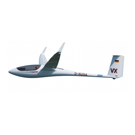
Alexander Schleicher ASK 21 Mi Technical specifications

Alexander Schleicher GmbH & Co. Segelflugzeugbau
36163 Poppenhausen - Germany
Flight Manual
No. 219.AFM.FAA.001
for the powered sailplane
ASK 21 Mi
Model: ASK 21 Mi
Serial Number:
Registration letters:
TC Data Sheet No.: G47EU
Issue: 01 December 2007
Pages identified by “Appr.” are approved by EASA /
FAA within the scope of type certification.
This powered sailplane is to operate only in compliance with the
operating instructions and limitations contained herein.

Flight Manual ASK 21 Mi Flight Manual
App. Issue: 01.12.2007 mh / mg / mm
Revision: TN21 / 21.09.22
2.2
2.1 Introduction
This Section contains operating limitations, instrument markings and
basic placards necessary for the safe operation of the powered sailplane
ASK 21 Mi, and its standard systems, installations, and standard equip-
ment as provided by the manufacturer.
The operating limitations included in this Section and in Section 9 are ap-
proved by EASA.
2.2 Airspeed
Airspeed limitations (indicated airspeed IAS) and their operational signif-
icance are shown below.
Speed
IAS
Remarks
VNE Never exceed
speed for calm air
280 km/h
151 kts
174 mph
Do not exceed this speed in
any operation and do not
use more than 1/3 of control
deflection.
For flights beyond 2000m (6500 ft) altitude VNE must be reduced as pre-
scribed in the placard included in Section 4.5.6.
This placard must be affixed next to the A.S. I.
VRA
Maximum permis-
sible speed for
Rough Air
180 km/h
97 kts
112 mph
This speed must not be ex-
ceeded in strong turbulence.
Examples of rough air are
lee-wave rotors, thunder-
clouds, etc

Flight Manual ASK 21 Mi Flight Manual
App. Issue: 01.12.2007 mh / mg / mm
Revision: TN21 / 21.09.22
2.4
VPO
max
Maximum speed
for extending and
retracting the
propeller
120 km/h
65 kts
75 mph Do not extend nor retract
the propeller outside of
this speed range
VPO
min
Minimum speed
for extending and
retracting the
propeller
90 km/h
49 kts
56 mph
Maximum speed
with propeller ex-
tended
160 km/h
86 kts
99 mph
Do not exceed this speed
with the propeller extended

Flight Manual ASK 21 Mi Flight Manual
Issue: 01.12.2007 mh / mg / mm App.
Revision: TN21 / 21.09.22
2.7
2.5 Power-Plant Control Unit Markings
The following table shows the markings of the digital ILEC engine control
unit and the meaning of the colors employed.
Green Diode
Normal Operat-
ing Range
1800 to 7100
Yellow Diode
Caution Range
7100 to 7750
Red Diode
with LCD blinking,
impermissible range
at 7750 plus
Permanent LC-Display:
RPM Indication
(4 digits) [RPM]
Fuel Quantity
(2-digits) [Liter]
XXXX
0to 23
Display reading when pressing the white button:
Press 1 time:
Liquid Coolant Temperature
(3 digits)[°C]
H2O
XXX
Press 2 times:
Internal Cooling Air Temperature
(3 digits) [°C]
Air
XXX
Press 3 times:
Current fuel consumption
(4-digits) [Liter/h]
Fuel
XX.X
Press 4 times:
Engine Battery Voltage
(4 digits) [Volt]
U
XX.X

Flight Manual ASK 21 Mi Flight Manual
App. Issue: 01.12.2007 mh / mg / mm
Revision: TN21 / 21.09.22
2.8
2.6 Mass (Weight)
Max. Take-Off Mass:: 705 kg (1554 lb)
Max. mass of all non-lifting parts: 510 kg (1124 lb)
Max. mass in baggage compartment (wing root): each side 10 kg
(22 lb)
2.7 Center of Gravity
The limits of the C.G. range are as follows:
forward limit 234 mm (9.22 in) aft of datum (BP)
aft limit 469 mm (18.47 in) aft of datum (BP)
"BP" (German: Bezugspunkt) stands in this context for "Reference Da-
tum" which is identical with the wing leading edge at the wing root rib.
One example of calculating C.G. positions is given in Section 6 of the
ASK 21 Mi Maintenance Manual.
2.8 Approved Maneuvers
This powered sailplane is approved for normal sailplane and powered
sailplane operation (Airworthiness Category "Utility").
Within the scope of this Airworthiness Category the following aerobatic
maneuvers are approved – but only with the propeller tower retracted
Spin
Steep Climbing Turn
Lazy Eight
Loop upwards
2.9 Maneuvering Load Factors

Flight Manual ASK 21 Mi Flight Manual
App. Issue: 01.12.2007 mh / mg / mm
Revision: TN21 / 21.09.22
2.10
2.10 Flight Crew
For solo flights the pilot must occupy the front seat.
With two up, the pilot in command occupies the front seat – unless the
occupants agree prior to the flight that the pilot in command occupies the
rear seat. This is only possible on the condition that all necessary operat-
ing elements and instruments are available in the rear seat and that the
pilot is familiar with the operation of the aircraft from this position.
The minimum front seat payload is shown in the Operating Limitations
Placard affixed in the front cockpit at the right wall (DATA and LOADING
PLACARD).
One third of the weight of the rear pilot contributes to the payload in the
front seat.
Lack of payload must be compensated by additional trim ballast weight.
For this refer to the Mass and Balance Form in Section 6 and the descrip-
tion of trim ballast in Section 7.
2.11 Types of Operation
Flights may be carried out in accordance with day VFR.
Cloud Flying is permissible in compliance with the extended minimum
equipment (see Section 2.13).
NOTE
The legal regulations of the appropriate civil aviation authority with
regard to any operational requirements have to be met. For exam-
ple for US operators, “Cloud Flying” is considered flying in Instru-
ment Meteorological Conditions (IMC) and requires an Instrument
Flight Rules (IFR) clearance in the U.S.
Flight Manual ASK 21 Mi Flight Manual
Issue: 01.12.2007 mh / mg / mm App.
Revision: TN21 / 21.09.22
2.11
2.12 Fuel and Oil
Add FUEL ONLY - WITHOUT two-stroke oil mixed. Two-stroke oil must
be added separately through the oil fill port.
Capacity of the fuselage tank: 23.2 Liter 6.13 US Gal
Max. fuel quantity usable in flight: 23.0 Liter 6.08 US Gal
Non-usable fuel: 0.2 Liter 0.05 US Gal
Approved Octane Rating: minimum 95 ROZ
Approved fuel grade: preferably AVGAS 100LL
EUROSUPER, in compliance with
EN228, or equivalent quality
In the USA "US 95 Octane rating" complies with the minimum require-
ments prescribed by the engine manufacturer.
Maintenance Instruction "Fuel" must be regarded, it is included in the An-
nex of the Maintenance Manual. For further data refer also to the Engine
Manual IAE50R-AA.
Engine oil:
preferably Silkolene Comp 2 Pre-mix (not Comp 2 Injector)
else: Bardahl KGR injection oil,
Castrol Aviation A545
Spectro Oils of America "Golden Spectro".
Oil tank capacity: 0.73 Liter 0.19 US Gal
Usable oil in flight: 0.70 Liter 0.18 US Gal
Non-usable oil: 0.03 Liter 0.01 US Gal

Flight Manual ASK 21 Mi Flight Manual
App. Issue: 01.12.2007 mh / mg / mm
Revision: TN21 / 21.09.22
2.12
2.13 Minimum Equipment
Minimum Equipment consists of:
1 ASI indicating up to 300 km/h (162 kts), in each instrument panel
1 Altimeter, in each instrument panel
1 Magnetic Compass, in the front instrument panel
1 ILEC engine control unit, in each instrument panel
1 Rear view mirror
1 5-part seat harness (symmetrical), in each seat
1 parachute or back cushion (with about same thickness as a para-
chute, when compressed), for each pilot
For flights beyond the circuit of the airfield an aircraft radio is mandatory
(for Germany). In addition, headphones should be worn when the engine
is running.
Caution: When the engine is running, sufficient ear protection
is strongly recommended!
For cloud flying the following instruments must be installed in addition:
1 Turn & slip indicator
1 Variometer
Approved equipment is listed in the Maintenance Manual in Section 12.1.

Flight Manual ASK 21 Mi Flight Manual
App. Issue: 01.12.2007 mh / mg / mm
Revision: TN21 / 21.09.22
2.14
2.15 Operating Limitations Placard
This placard is fixed at the right cockpit side wall and contains the most
important mass and speed limitations.
For reduced minimum cockpit load in the front seat by fitting removable
trim ballast in front of the pedals: see Section 7.11.
The baggage compartment load in the wing roots must not exceed 10 kg
(22 lbs) for each side.
This placard is fixed at the right cockpit side wall:
Spin

Flight Manual ASK 21 Mi Flight Manual
Issue: 01.12.2007 mh / mg / mm App.
Revision: TN21 / 21.09.22
2.15
This placard is affixed on the fuselage tank:
This placard is affixed on the right wall of the engine compartment near
the oil tank:
If the aircraft has not installed the minimum equipment for cloud flying
(see 2.13), this placard is located near the data placard:
If the aircraft has installed the minimum equipment for cloud flying (see
2.13), this placard is located near the data placard:

Flight Manual ASK 21 Mi Flight Manual
App. Issue: 01.12.2007 mh / mg / mm
Revision: TN21 / 21.09.22
3.2
3.1 Introduction
This Section contains Check Lists, summarizing procedures recom-
mended in the case of emergencies, in the form of brief headings.
This is followed by a more detailed description.
EMERGENCY PROCEDURES
(1) To Jettison Canopies
-
Ignition: OFF!
-
Engage the propeller stop
front seat
rear seat
-
Move lever with red knob
above the instrument
panel to the left
-
Fully pull back both red
canopy locking handles
-
Push canopy upwards
-
Push canopy upwards
by the handles
(2) Bailing Out
front seat
rear seat
-
Push instrument panel
upwards
-
Open safety harness
-
Open safety harness
-
Get up
-
Get up
-
Climb over cockpit side
-
Roll over cockpit side
-
Push off strongly
-
Push off strongly
-
Avoid wing & tailplane!
-
Avoid wing & tailplane!
-
Pull parachute
-
Pull parachute

Flight Manual ASK 21 Mi Flight Manual
Issue: 01.12.2007 mh / mg / mm app.
Revision: TN21 / 21.09.22
3.5
3.3 Bailing Out
If bailing out becomes inevitable, first the canopy is jettisoned, and only
then should the seat harness be released.
Front Pilot: Push instrument panel upwards (if this was not yet al-
ready done in the course of jettisoning the canopy). Get
up or simply roll over cockpit side.
Rear Pilot: Get up - the supporting structure at either side of the in-
strument panel and the canopy arch serve as handholds
- and climb out.
When jumping, push yourself away from the aircraft as strongly as possi-
ble.
Avoid wing leading edge and tailplane!

Flight Manual ASK 21 Mi Flight Manual
Issue: 01.12.2007 mh / mg / mm app.
Revision: TN21 / 21.09.22
3.9
3.7 Engine Failure
(1) Failure at Safe Altitude
- Fuel Valve: OPEN (foremost position)
- Ignition: ON (upward position)
- Power-Plant Main Switch: ON (ILEC responding)
- Master switch for engine battery: ON (ILEC responding)
- Fuel pump 2: ON
- Fuel: Check fuselage tank contents
- ILEC Change Over Switch: Turned towards the pilot
If the above points check out correctly, the fault cannot be rectified in
flight, the propeller should be retracted and the ASK 21 Mi should from
then on be operated as a pure sailplane. Retract propeller in the normal
manner in accordance with the check list.
If necessary, carry out a normal sailplane outlanding.
(2) Failure at Low Altitude
First check the points on the above check list.
- Fuel Valve: SHUT! (rearmost position)
- Ignition: OFF!
- Power-Plant Main Switch: OFF!
- Propeller Stop: ENGAGED! (bottom position)
- Leave the propeller extended
- Initiate outlanding
If the situation becomes so critical that a crash landing seems unavoida-
ble because no landable terrain can be reached, the propeller stop should
be engaged at a speed of about 90 km/h (49 kts) - even with the propeller
still running. This will help to stop the propeller more quickly. Then retract
the propeller at least to a "halfway in" position.

Flight Manual ASK 21 Mi Flight Manual
Issue: 01.12.2007 mh / mg / mm app.
Revision: TN10 / TN21 / 21.09.22
3.9
3.7 Engine Failure
(1) Failure at Safe Altitude
- Fuel Valve: OPEN (foremost position)
- Ignition: ON (upward position)
- Power-Plant Main Switch: ON (ILEC responding)
- Master switch for engine battery: ON (ILEC responding)
- Fuel pump 2: ON
- Fuel: Check fuselage tank contents
- ILEC Change Over Switch: Turned towards the pilot
If the above points check out correctly, the fault cannot be rectified in
flight, the propeller should be retracted and the ASK 21 Mi should from
then on be operated as a pure sailplane. Retract propeller in the normal
manner in accordance with the check list.
If necessary, carry out a normal sailplane outlanding.
(2) Failure at Low Altitude
First check the points on the above check list.
- Fuel Valve: SHUT! (rearmost position)
- Ignition: OFF!
- Power-Plant Main Switch: OFF!
- Propeller Stop: ENGAGED! (bottom position)
- Leave the propeller extended
- Initiate outlanding
If the situation becomes so critical that a crash landing seems unavoida-
ble because no landable terrain can be reached, the propeller stop should
be engaged at a speed of about 90 km/h (49 kts) - even with the propeller
still running. This will help to stop the propeller more quickly. Then retract
the propeller at least to a "halfway in" position.

Flight Manual ASK 21 Mi Flight Manual
App. Issue: 01.12.2007 mh / mg / mm
Revision: TN21 / 21.09.22
3.12
3.9 Other Emergencies
(1) Groundloops
If the aircraft threatens to roll out beyond the intended landing area, the
decision should be made not less than 40 m (140 ft) before reaching the
end of the landing area to initiate a controlled ground loop.
- If possible, turn into wind!
- When putting down the wing, at the same time push the
stick forward and apply opposite rudder!
(2) Strong Noise Development Due To Defective Exhaust Silencer
If the noise from the exhaust silencer is considerably increasing, a failure
of the exhaust system must be taken into account. Because hot exhaust
fumes may cause fire, the engine must be stopped immediately or after
reaching a safe height respectively. Prior to the next flight the exhaust
system must be inspected and if necessary repaired.
(3) Throttle Cable Broken
If the throttle cable fails, a spring at the throttle valve housing opens the
throttle valve wide open and the engine is running at full throttle. Climb to
a safe height, switch off the ignition, let the propeller run down so that it
can be retracted in the normal manner.
If no airfield or landable terrain is nearby and further height gain is not
possible, you may prevent a further climb by using the airbrakes. Then
you may continue the flight in this configuration until you can reach an
airfield. Prior to landing switch off the ignition and retract the propeller.

Flight Manual ASK 21 Mi Flight Manual
Issue: 01.12.2007 mh / mg / mm app.
Revision: TN21 / 21.09.22
3.13
(4) Defective Airbrake Control Circuit
If sudden strong change of flight course happens, the pilot should imme-
diately visually check that the airbrakes have extended on both wings as
this asymmetry may be caused by an airbrake extended on one wing only.
This problem could occur after a defect in the airbrake control circuit and
cannot be compensated by rudder deflection. If the airbrake has extended
on one wing only, the other airbrake must immediately be extended so far
that the aircraft will regain level flight and the airbrake lever must be held
in this position.
Depending on the flight height immediately initiate an outlanding.

Flight Manual ASK 21 Mi Flight Manual
App. Issue: 01.12.2007 mh / mg / mm
Revision: TN21 / 21.09.22
4.6
4.3 Daily Inspection
1) Open canopies. Check main pins inserted up to the handle and se-
cured.
2) Check control connections of ailerons and air brakes in the fuselage
through the access hole at the left side above the wing. Check the
proper use / engagement of the safety elements on the quick-release
connectors. Finally, the access hole cover must be taped up!
3) Check cockpit and control runs for loose objects.
4) Check condition and operation of towing hooks, especially for soiling
and free actuation. Engage and disengage the ring pair. Check the
automatic release of the C.G. towing hook with the ring pair, which
must release automatically backwards.
5) Check free movement of all controls. Check the plastic tubes inside
the S-shaped tubes of the rudder pedals for correct and tight fit.
6) Check wheel brake. Pull the air brakes lever: with airbrake paddles
fully extended the resilient brake pressure from the main brake (mas-
ter) cylinder should be felt through the brake handle.
7) If your aircraft is fitted with a steerable nose wheel (optional), check
its operation!
8) Check condition of Pitot tube in the fuselage nose!
9) Check tire pressure in the wheels!
10) Check the whole fuselage for damages, in particular the bottom side!
11) Check both upper and lower surfaces of the wing for damage.
12) Ailerons: Check condition, play and full and free movement. Check
also the push rod connections.

Flight Manual ASK 21 Mi Flight Manual
Issue: 01.12.2007 mh / mg / mm App.
Revision: TN21 / 21.09.22
4.7
13) Air brake: Check condition, free movement, alignment and locking.
14) Check the rear wing attachment pins for proper seating and locking.
15) Check that static ports in the fuselage tail boom are unobstructed!
16) Pressure probe on the tail boom or optional in the fin: Check condi-
tion and proper seating.
17) Check the condition of the rudder. Check the rudder for free move-
ment, excessive play and proper securing of the cable connections.
18) Check tailplane for correct assembly and connection. Check elevator
and actuator for condition, free movement and play!
19) Check control linkages of elevator, aileron, rudder and air brakes for
free movement and for force-fit. Hold controls firmly at full deflection
while loads are applied to stick, pedals and air brakes lever respec-
tively.
20) Turn on master switch for engine battery. It can be left on for the day.
After rough landings or excessive flight stress the whole aircraft must be
checked with the wings and tail unit removed. If any damage is found, a
technical inspector must be called in. On no account one must take off
again before the damage has been repaired.

Flight Manual ASK 21 Mi Flight Manual
Issue: 01.12.2007 mh / mg / mm App.
Revision: TN10 / TN21 / 21.09.22
4.7
13) Air brake: Check condition, free movement, alignment and locking.
14) Check the rear wing attachment pins for proper seating and locking.
15) Check that static ports in the fuselage tail boom are unobstructed!
16) Pressure probe on the tail boom or optional in the fin: Check condi-
tion and proper seating.
17) Check the condition of the rudder. Check the rudder for free move-
ment, excessive play and proper securing of the cable connections.
18) Check tailplane for correct assembly and connection. Check elevator
and actuator for condition, free movement and play!
19) Check control linkages of elevator, aileron, rudder and air brakes for
free movement and for force-fit. Hold controls firmly at full deflection
while loads are applied to stick, pedals and air brakes lever respec-
tively.
20) Turn on master switch for engine battery. It can be left on for the day.
After rough landings or excessive flight stress the whole aircraft must be
checked with the wings and tail unit removed. If any damage is found, a
technical inspector must be called in. On no account one must take off
again before the damage has been repaired.

Flight Manual ASK 21 Mi Flight Manual
Issue: 01.12.2007 mh / mg / mm App.
Revision: TN21 / 21.09.22
4.9
Daily Inspection with Extended Propeller
a) When extending the propeller pay attention to unusual noise and stiff-
ness of operation.
b) The most important bolted connections can be checked from above
through the open engine bay doors. With one exception they are se-
cured with standard stop nuts, and therefore are easy to check. Par-
ticular attention must be paid to both front engine mounting screws
and to the bolted connections of the extending toggle crank with jack
head.
c) The rear engine mounting screw which is running through the engine
oil tank is secured with locking wire. Check this locking wire for dam-
age.
d) By pushing against the propeller assembly from the side and from the
front, check the rubber elements of the engine mounting. The power-
plant should react flexible and should not immediately move against
the fuselage structure.
e) Check the toggle over dead center of the drive mechanism of the pro-
peller assembly! Check that both sides have a good over-center lock.
f) Inspect the mounting of the exhaust silencer. The spring mountings
can be checked by shaking the silencer.
g) Check mounting of radiator, and the radiator support plate for incipient
cracks.
h) Check operation of throttle and propeller stop mechanism.
i) Check Bowden cables, fuel lines and hoses for kinks. Check the con-
dition of the elastic cords of the engine bay doors.
j) Inspect lines (especially fuel lines and coolant hoses) and all compo-
nents for signs of chafing.
k) Check mounting of the flexible ram pipe. Check the securely seating
of the air filter at the ram pipes upper end.
Other manuals for ASK 21 Mi
1
Table of contents
Other Alexander Schleicher Aircraft manuals

Alexander Schleicher
Alexander Schleicher ASK 21 B User manual

Alexander Schleicher
Alexander Schleicher AS 33 ES Technical specifications

Alexander Schleicher
Alexander Schleicher ASK 21 B Technical specifications

Alexander Schleicher
Alexander Schleicher ASK 21 Mi Technical specifications

Alexander Schleicher
Alexander Schleicher ASH 31 Mi Technical specifications

Alexander Schleicher
Alexander Schleicher ASH 26 E User manual