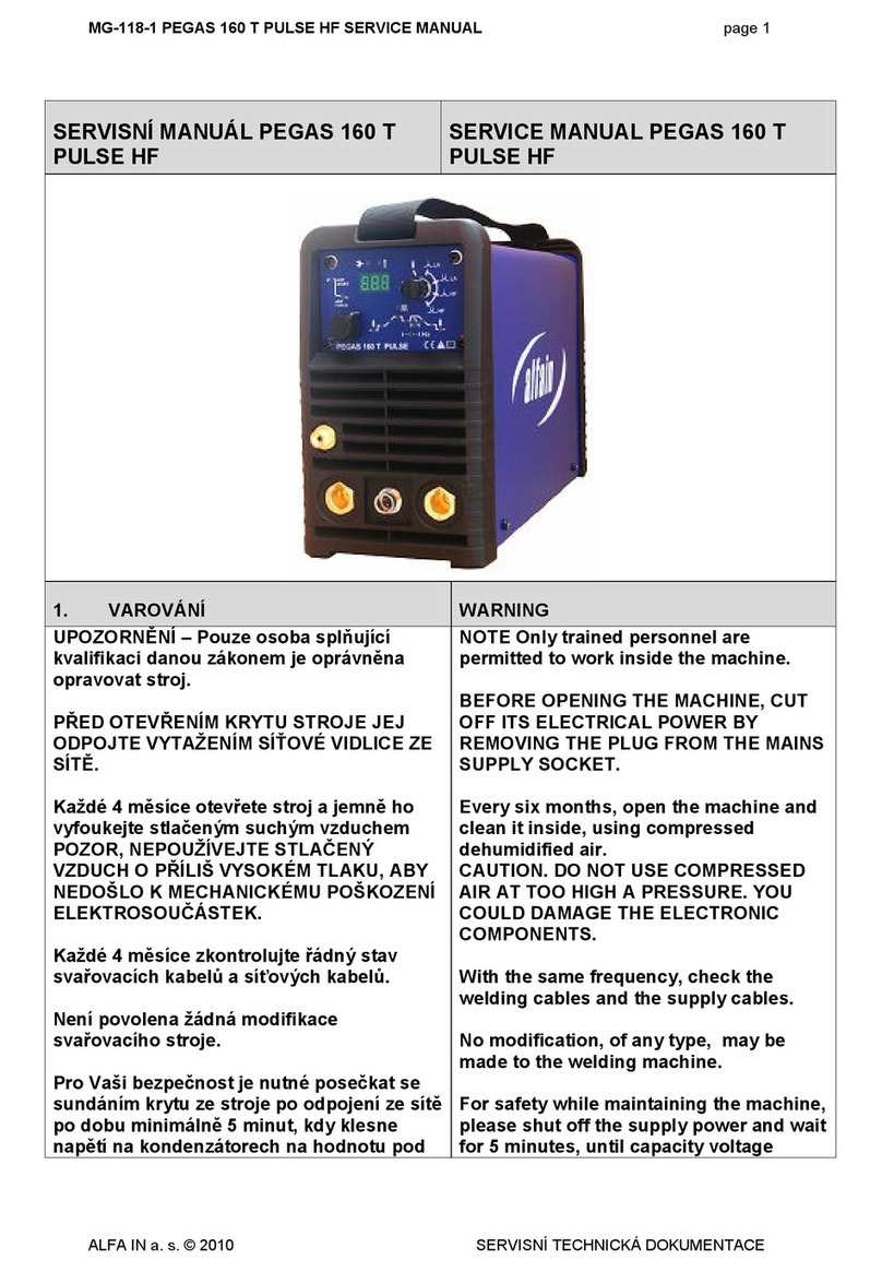
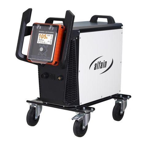
Alfa Network PERUN 200 AC/DC PULSE User manual

ALFA IN a.s. © www.alfain.eu PERUN 200 AC-DC (Pulse) manual EN 07
WELDING INVERTER
PERUN 200 AC/DC PULSE
PERUN 200 AC/DC
OPERATING MANUAL

2/22
ALFA IN a.s. © www.alfain.eu
CONTENT
INTRODUCTION .......................................................................................... 3
2 SAFETY PRECAUTIONS ............................................................................ 4
3 OPERATING CONTROLS ........................................................................... 5
4 TECHNICAL DATA ...................................................................................... 6
5 EQUIPMENT ................................................................................................ 7
6 OPERATOR CONTROLS ............................................................................ 9
7 GETTING STARTED ................................................................................. 3
8 TWO STROKE AND FOUR STROKE IN TIG MODE ............................... 8
9 JOBS .......................................................................................................... 9
0 RESET........................................................................................................ 9
GENERAL INFORMATION ON THE WELDING MODES......................... 20
2 ROUTINE MAINTENANCE & INSPECTION ............................................. 2
3 STATEMENT OF WARRANTY .................................................................. 2
4 DISPOSAL ................................................................................................. 22
5 WARRANTY LIST ...................................................................................... 22

3/22
ALFA IN a.s. © www.alfain.eu
1 INTRODUCTION
Dear consumer,
Company ALFA IN a.s. thanks you for buying our product and believe that you
will be satisfied with our machine.
This Operating Manual has been designed to instruct you on the correct use and
operation of your ALFA IN product. Your satisfaction with this product and its
safe operation is our ultimate concern. Therefore please take the time to read
the entire manual, especially the Safety Precautions. They will help you to avoid
potential hazards that may exist when working with this product.
Read and understand this entire Manual and your employer’s safety practices
before installing, operating, or servicing the equipment. While the information
contained in this Manual represents the Manufacturer's best judgement, the
Manufacturer assumes no liability for its use.
PERUN 200 AC/DC (PULSE) welds by those methods:
. TIG (PULSE) DC (Lift arc or High Frequency ignition)
2. TIG (PULSE) AC (Lift arc or High Frequency ignition)
3. MMA DC coated electrodes
4. MMA AC coated electrodes
PERUN 200 AC/DC (PULSE) have these special functions for effective use:
Pre gas (only for PULSE model) and Post gas of protective gas, Up slope
(only for PULSE model) and Down slope, Starting current and Final current
(only for PULSE model), HF ignition, 2T and 4T mode, Aluminum cleaning level,
Pulsed mode (only for PULSE model), Bilevel and UP-DOWN control from the
torch.
For MMA method are these machines equipped with functions HOT START,
ARC FORCE and ANTISTICK.
Welding machine may be operated only by trained persons and only in the
technical provisions. Company ALFA IN a.s. accept no responsibility for damage
caused by improper use. Before commissioning please read carefully this
manual.
The machine complies with the appropriate CE mark.
For maintenance and repairs, use only original spare parts. There is of course a
complex of our services.
We reserve the law of adjustments and changes in case of printing errors,
change of technical paramaters, accessories etc. without previous notice.
These changes may not be reflected in the manuals for use in paper or electronic
form.

4/22
ALFA IN a.s. © www.alfain.eu
2 SAFETY PRECAUTIONS
PERSONAL PRECAUTION
. For safety reasons, it is necessary to use welding gloves during welding.
These gloves will protect you before intervention of electric current
(open circuit voltage). It protects you against thermal radiation and
splashing drops of hot metal too. Wear sturdy isolated shoes. Do not wear
open shoes, because drops of hot metal can cause burns.
2. Do not look into the welding arc without eye and face protection.
Always use good quality welding helmet with intact protective filter.
3. The persons appearing in the vicinity of the welding must be informed of
the danger and must be equipped with protective equipment.
4. During welding, especially in small spaces, it is necessary to ensure an
adequate supply of fresh air, because during welding, harmful fumes arise.
5. In tanks of gas, oil, fuel, etc., (even empty ones) do not make welding,
because there is a chance of explosion.
6. In areas with chance of explosion special provisions are applied.
7. Welding machines that are subjected to great exertion must comply with
specific security requirements. These include the rail pressure of the
vessel etc. These connections may only be carried out by competently
trained welders with the necessary permissions.
SAFETY REGUALTIONS
. Before starting work with welding machine, it is necessary to get familiar
with the provisions of the CSN 05060 and norm CSN 050630.
2. With a bottle of CO2 or mixed gases should be handled according to the
regulations for working with pressure vessels contained in CSN 07 83 05.
3. The welder must use protective equipment.
4. Before working on the electrical part, removing the cover or cleaning it is
necessary to disconnect the device from the network.

5/22
ALFA IN a.s. © www.alfain.eu
3 OPERATING CONTROLS
. Putting the machine into operation can be performed only by trained
personnel and only within the technical provisions. The manufacturer is not
liable for damages resulting from improper use or handling.
For maintenance and repair, use only original spare parts from ALFA IN.
2. Device complies with IEC 6 000-3- 2.
3. The welding machine is tested according to the degree of protection
IP 23S, which provides protection against the intrusion of solid bodies with
a diameter greater than 2 mm and protection against ingress of water,
falling on the machine in a vertical direction or max degree of 60°.
4. Working ambient temperature between - 0 and +40 °C.
5. Relative humidity below 90% at +20 °C.
6. Up to 3000 m altitude.
7. The machine must be positioned so that cooling air can enter and leave
through cooling vents with no problem. It is necessary to ensure that there
are no mechanical equipment, especially metal particles (e.g. during
grinding) drawn into the machine.
8. It is necessary for welding machine to undergo a periodic inspection every
6/ 2 months by an authorized officer according to CSN 33 500 and CSN
050630 – see Maintenance and service tests.
9. All interventions in the el. equipment as well as repair (removal of the plug,
fuse replacement) should be performed by an authorized person.
0. With competent mains voltage and input must match the plug.
Caution E tension cables must not have conductors with a smaller
cross section than 3 2,5 mm2. The machine can be operated on a single-
phase electric generator 10 kVA (1 230V/50Hz) and more, which has
ensured voltage stabilization ± 10%. Generators with lower power can
damage the machine.
. It is necessary to protect the machine against:
a. Moisture and rain
b. Chemically aggressive environments
c. Mechanical damage
d. Draft and possibly ventilation of neighboring machines
e. Excessive overloading – exceeding tech. parameters
f. Rough treatment
ELECTROMAGNETIC COMPATIBILITY
The welding device is in terms of interference designed primarily for industrial
areas. It meets the requirements of EN 60974- 0 class A and it isn’t designed
for using in residential areas, where the electrical energy is supplied by public
low-voltage power supply network. It can be here potential problems with
ensuring of electromagnetic compatibility in this areas, due to interference
caused by power lines as well as the radiated interference.
During operation, the device may be the source of interference.

6/22
ALFA IN a.s. © www.alfain.eu
Caution
We warn users, that they are responsible for possible interference from
welding.
4 TECHNICAL DATA
Method MMA - AC MMA - DC TIG - AC TIG - DC
Mains voltage V/Hz
x230/50-60
Welding current range A 0 - 70 0 - 70 0 -200 0 - 70
Open-circuit voltage U20 V --- 63,0 --- 63,0
Mains protection A 6 @ (25 @)
Max. effective current I eff A 6,0 (22,7) 6,0 ( 7,3)
Welding current (DC= 00%)
I2 ta=40 oC A 80 ( 0) 80 ( 0) 20 ( 20) 20( 20)
Welding current (DC=60%) I2
ta=40 oC A 00 ( 40) 00 ( 40) 40 ( 40) 40 ( 40)
Welding current (DC=x%) I2
ta=40 oC A 20%= 70
(40%= 70)
20%= 70
(40%= 70)
30%=200
(35%=200)
40%= 70
(40%= 70)
Protection IP23S
Standards EN 60974- , EN 60974- 0 cl. A
Dimensions (w x l x h) mm
60 x 530 x 3 0
Weight kg 9,5
The machine is equipped with a 6 A plug for connection to a single-phase
supply x 230 V, the corresponding data for this 6 A plug (Duty Cycle = DC)
are in the table above without brackets.
In order to fully use the technical capabilities of the machine, the machine must
be connected to the industrial single-phase networks with a blue plug 32 A with
the maximum permissible fuse of 25 A. The corresponding data for such a 32 A
plug are stated in the table above in brackets.
Another option is to connect the machine to the three-phase mains 3x400 / 230V
TN-S (CS). The condition is to use a 5 pin 32 A plugs for the supply cable and
connection to the phase voltage. Black (brown) wire connected to one phase
(e.g. L ), the blue wire to the neutral wire (N) and green-yellow wire to the
grounded conductor "PE". In this case, it is possible to connect the machine to
a three-phase socket, which may be protected by fuse max. 25 A.
Attention! Do not connect to the interconnected voltage (delta voltage) (between
2 phases)!
Replacement of the plug may only be performed by ALFA IN authorized service
personnel.

7/22
ALFA IN a.s. © www.alfain.eu
ALFA IN continuously strives to produce the best product possible and therefore
reserves the right to change, improve or revise the specifications or design of
this or any product without prior notice. Such updates or changes do not entitle
the buyer of equipment previously sold or shipped to the corresponding changes,
updates, improvements or replacement of such items.
5 EQUIPMENT
CONTENT OF DELIVERY
Item No.
Description Picture
5.0293 PERUN 200 AC/DC Pulse
5.0294 PERUN 200 AC/DC
ACCESSORIES TO ORDER
Item No. Description Picture
VM0 5 - Hose Gas 3m G /4-G /4
VM0253 Welding Cable Set 2x 3m
35-50 200A
5.0508 Welders Cart P 80

8/22
ALFA IN a.s. © www.alfain.eu
T24ST Torch T2 4m 35-50 arc
ST
T28ST Torch T2 8m 35-50 arc
ST
T24STUD Torch T2 4m 35-50 arc
ST UD
T28STUD Torch T2 8m 35-50 arc
ST UD
6008
Pressure Reducer
FIXICONTROL Ar 2
manometers GCE
7029 Belt PERUN
S7SUN9B Welding Helmet S9B
Shooting Blue Shark
S7SUN9BBlack
Welding Helmet S9B
Shooting Blue Shark
Black
5.0 74ST Foot Pedal Remote CTRL
3 m incl. Connector ST

9/22
ALFA IN a.s. © www.alfain.eu
6 OPERATOR CONTROLS
MAIN PARTS
Fig. . Main parts
Pos. Description
A Operating panel
A2 Torch control connector
A3 Quick connector (-)
A4 Gas connector of the welding torch
A5 Quick connector (+)
A6 ON/OFF switch
A7 Gas inlet
A8 Mains cable and plug

0/22
ALFA IN a.s. © www.alfain.eu
OPERATING PANEL
Fig. 2. Operating panel of PERUN 200 AC/DC PULSE
Fig. 3. Operating panel of PERUN 200 AC/DC

/22
ALFA IN a.s. © www.alfain.eu
Pos. Description
V LED. If illuminated the method MMA was selected.
V2 LED. If illuminated the method TIG LIFT ARC was selected.
V3 LED. If illuminated the method TIG HF was selected.
V4 Switch AC/DC
V5 LED AC
V6 LED DC
V7 LED Pre gas, 0, – 2,0 s. (0,3 s)
V8 LED Starting current (only for 4T). 0 – 70 A in DC, 0 – 200 A in
AC. (50 A)
V9 LED Up slope, 0 – 25 s. (0 s)
V 0 LED Main welding current. 0 - 70 A (TIG-DC);0 - 200 A
(TIG-AC);0 – 70 A (MMA-AC/DC) (80 A all methods)
V Encoder
V 2
LED – Pulsed mode; To change, rotate the encoder V11 and
confirm by means of pressing the encoder V11 down. Display V25
shows -P-.
V 3
LED – Non pulsed mode; To change, rotate the encoder V11 and
confirm by means of pressing the encoder V11 down. Display V25
shows ---.
V 4 LED Pulse frequency. 0,5 – 200 Hz. Just for pulsed mode. ( 00 Hz)
V 5 LED Balance (only for TIG AC). It is used for elimination of
aluminum oxide. Range from -5 to +5. (0)
V 6 LED Post gas, 0 – 20 s. ( 0 s)
V 7 LED Final current. 0 – 70 A in DC, 0 – 200 A in AC, just in 4T.
( 0 A)
V 8 LED Down slope, 0 – 25 s. (0)
V 9 LED 4T (four stroke)
V20 Switch 2T/4T
V2 LED 2T (two stroke)
V22 LED ARC FORCE, only for MMA, 0 – 00. (30)
LED lights up after pressing the encoder V11.
V23 LED Welding current for MMA, 0 – 70 A (only for MMA) (80)
LED lights up after pressing the encoder V11.
V24 LED HOT START, only for MMA, 0 – 00. (50)

2/22
ALFA IN a.s. © www.alfain.eu
LED lights up after pressing the encoder V11.
V25 Display
V26 LED ALARM. If illuminated there is under or over voltage in the
mains or the machine is overheated.
V27 LED Ratio of the pulse current and the base current. 5 – 95 %.
(50 %) Just for the pulsed mode.
V28 LED Voltage. If illuminated there are values in V on the display V25.
V29 LED Current. If illuminated there are values in A on the display V25.
V30 LED Lower current. 0 – 70 A (TIG-DC);0 – 200 A (TIG-AC);
0 – 70 A (MMA-AC/DC)
V3 LED s. If illuminated there are values in s on the display V25.
V32 LED %. If illuminated there are values in % on the display V25.
V33 LED Hz. If illuminated there are values in Hz on the display V25.
V34 Welding method switch – MMA / TIG LIFT ARC / TIG HF.
V35 LED ON

3/22
ALFA IN a.s. © www.alfain.eu
7 GETTING STARTED
Getting started must be consistent with technical data and conditions of use.
GETTING STARTED MMA – COATED ELECTRODE
Fig. 4. Ways of connecting the welding cables. Follow the instructions on the
packing of the welding electrodes.
. Insert the mains plug A8 into a suitable x230 V mains socket.
2. Connect the welding cables to the panel quick connectors (+) A5 and (-)
A3 according the instruction on the electrodes packing.
3. Switch the machine on by the ON/OFF switch A6.
4. By means of the welding method switch V34 select MMA method. The
corresponding LED V1 will light up.
5. By means of the encoder V11 set the welding current. The values will be
showed on the display V25.
6. By means of the button V4 select AC or DC welding current. The
corresponding LED V5 or V6 will light up.
7. It is possible to change the settings of the HOT START (increase of current
during arc ignition time), ARC FORCE (an automatic increase of the
welding current in case the electrode touches the welding piece) by means
of the encoder V11.
NOTE Prevent touching the electrode any metal material for in this mode
the quick connectors A5 and A3 are under current.
8. Insert the coated electrode into the electrode holder, connect the clamps
of the ground cable to the welding piece and you may start welding.

4/22
ALFA IN a.s. © www.alfain.eu
TABLE OF ELECTRODE CONSUMPTION DURING WELDING
Electrode
diameter
[mm]
Range of
welding
current [A]
Total
electrode
length [mm]
Weight of
boiled
electrode
without slag
[g]
Boiled
electrode
time [s]
Weight of
boiled
electrode
without slag
per 1 second
[g/s]
,6 30 - 55 300 4 35 0,
2,5 70 - 0 350 49 0,22
3,2 90 - 40 350 9 60 0,32
4,0 20 - 90 450 39 88 0,44
GETTING STARTED TIG
TORCH CONNECTION SCHEMA
5737 CONNECTOR ST 12 PIN MALE
PIN
NO.
FOOT PEDAL TORCH WITH
POTENTIOMETER
UP-DOWN
TORCH
SHORT CIRCUIT / /
2 / /
3 POTENTIOMETER
(+) POTENTIOMETER (+)
/
4 POTENTIOMETE
R
CENTER TAP
POTENTIOMETER
CENTER TAP /
5 POTENTIOMETER
(-) POTENTIOMETER (-) /
6 / / UP
7 / / DOWN
8 START/STOP START/STOP START/STOP
9 START/STOP START/STOP START/STOP
(GND)
0 / SHORT CIRCUIT /
/ /
2 / / /

5/22
ALFA IN a.s. © www.alfain.eu
Fig. 5. TIG welding set up
. Insert the mains plug A8 into a suitable x230 V mains socket.
2. Fit the TIG torch to the panel quick connector (-) A3.
3. Connect the torch control connector onto the matching connector A2.
4. Connect the gas hose of the TIG torch onto gas outlet connector A4.
5. Connect the work lead to panel quick connector (+) A5.
6. Connect the gas hose to the reduction valve on the gas cylinder and on
the Gas inlet connector A7 on the rear panel.
7. Switch the machine on by the ON/OFF switch A6.
8. Press the torch trigger, the solenoid valve will open; set the desired gas
flow (pure argon).
9. By means of the welding method switch V34 select TIG LA or HF method.

6/22
ALFA IN a.s. © www.alfain.eu
The corresponding LED V2 or V3 will light up.
0. By means of the switch V20 select 2T (two stroke) or 4T (four stroke)
mode. The corresponding LED V21 or V19 will light up.
. By means of the button V4 select AC or DC welding current. In the
welding torch must be installed a corresponding tungsten electrode (for AC
green or golden). The electrode should be sharpened also corresponding
to the AC or DC mode. The corresponding LED V5 or V6 will light up.
2. By means of the encoder V11 set the welding current.
3. Other parameters may be set by means of the encoder V11.
Illuminate the appropriate LED by means of pressing the encoder V11, by
means of turning the encoder V11 set the parameter and save it by means
of pressing the encoder V11. After that a next LED will illuminate and you
may set that parameter the same way. The set parameter will be
automatically memorised when you move to another parameter of after 3
s. At every turning of the encoder V11 the last selected parameter will be
offered to be changed.
4. Connect the work clamp to the work piece or at the welding table and
you can start welding.
TABLE OF CONSUMPTION DURING TIG WELDING
Wolfram electrode diameter [mm]
Argon flow [l/min]
Steel / stainless steel
0,5 3 – 4
,0 3 – 5
,6 4 – 6
2,4 5 – 7
3,2 5 – 9
The following table describes the influence setting the clearance effect.
Clearance effect Value -5 to 0 Value + to +5
Shape of the current
curve
Penetration
Shallow
Deep
Level of wear of the of
tungsten electrode
Smaller Bigger

7/22
ALFA IN a.s. © www.alfain.eu
REMOTE CONTROL
PERUN 200 AC/DC PULSE supports three kinds of remote controls:
. TIG torch with UP-DOWN buttons
2. Standard separate remote control for changing the value of the welding
current
3. Foot pedal
All three models of remote controls can be connected by means of the front panel
connector A2.
Fig. 6. Foot pedal remote control
Pos. Description
P Stepping surface
P3 Connector (connect to matching connector A2 on the front panel)
. When you connect the P3 connector to matching connector on the front
panel A2 the function setting the current from the front panel will blocked.
2. Set by the encoder V11 the maximal required value of the current.
3. Set the machine to the mode 2T.
4. By pressing the stepping surface P1 down you start the welding process.
The value of the welding current depends on the level of pressing the
stepping surface. To reach the maximal current, set by encoder V11,
requires to gently pressing to the lowest position of the stepping surface
P1. The set current will be displayed on the display V25.
5. The welding process ends after releasing the stepping surface P1.

8/22
ALFA IN a.s. © www.alfain.eu
8 TWO STROKE AND FOUR STROKE IN TIG MODE
TWO STROKE – 2T
FOUR STROKE – 4T
BILEVEL – SECOND WELDING CURRENT
When the machine is in 4T mode, there is always active the BILEVEL function.
The value of the second current is automatically set to 50% of the pre-set value
of the main welding current. To enter the second welding current press the torch
button for a short time and release it. To get back to the main welding current
press the torch button for a short time and release it.
Gas
Pregas Postgas
Down slope
Welding current
Current
Gas
Down slope
Post
gas
Up slope
Pregas
Welding current
Current

9/22
ALFA IN a.s. © www.alfain.eu
9 JOBS
JOBs are available in both methods – MMA and TIG.
The welding machine has a choice from 0 JOBs.
HOW TO SAVE PARAMETERS TO THE JOB
. Parameters, which you want to save to the JOB, set by means of the
encoder V11. (By short pressing the encoder V11 switch between
particular parameters of the curve or functions.)
2. As soon as you will have saved all parameters, then by long pressing the
encoder V11 get into the JOBs menu. The display V25 will show -S-. In the
JOBs menu are two positions: -S- (Save) and -L- (Load).
3. By short pressing the encoder V11 confirm the message -S- on the display
V25 to save your choice of parameters or functions. The display V25 will
show numbers from 2 to for particular JOBs. Rotate the encoder V11
to select the desired JOB number, into which you want to save your
selected parameters, then confirm your choice by short pressing the
encoder V11.
HOW TO LOAD THE SAVED JOB
. By long pressing the encoder V11 get into the JOBs menu. The display
V25 will show -S-.
2. Rotate the encoder V11 to move to the position -L-. By short pressing the
encoder V11 confirm the position -L-.
3. The display V25 will show numbers from 2 to for particular JOBs. Rotate
the encoder V11 to select the desired JOB number, from which you want
to load your selected parameters, then confirm your choice by short
pressing the encoder V11.
HOW TO DELETE SAVED PARAMETERS FROM THE JOB
It is not possible to delete parameters from the JOB, they can be only replaced
by new parameters. To save new parameters, see the chapter HOW TO SAVE
PARAMETERS TO THE JOB above.
10 RESET
The factory reset is performed as follows:
. By long pressing the encoder V11 get into the JOBs menu. The display
V25 will show -S-.
2. Rotate the encoder V11 to move to the position -L-. By short pressing the
encoder V11 confirm the position -L-.
3. Rotate the encoder V11 and select the number 1, which is designed for
factory reset, then confirm your choice by short pressing the encoder V11.

20/22
ALFA IN a.s. © www.alfain.eu
11 GENERAL INFORMATION ON THE WELDING
MODES
MMA welding
The manufacturers of the electrodes specify the optimum welding current for
each type of electrode. The type of electrode to be used depends on the
thickness of the material to be welded and on its position.
Insert the chosen electrode into the electrode holder. To strike the electric arc,
rub the electrode against the material to be welded connected to the earth
(ground) clamp. Once the arc is struck, lift the electrode holder slowly to the
normal welding distance.
To strike the arc better, an initial current is supplied which is higher (hot-start)
compared to the welding current. The electrode on melting deposits in the form
of drops onto the piece to be welded and its outer coating is consumed supplying
the shielding gas for the welding. To facilitate the fluidity of the welding arc, while
the drops are coming off, which can cause a short circuit between the electrode
and the weld pool, a momentary increase in the welding current (arc-force) is
given, thus preventing the arc from going out. If the electrode stays stuck to the
piece to be welded, there is an anti-stick function that, after a certain short-circuit
time, cuts off the power to the generator. Thus you can detach the electrode
without damaging it.
When the coating electrodes are used, you need to remove the dross from the
welding after every pass.
TIG welding
In TIG (Tungsten Inert Gas) welding the electric arc is struck between a non-
consumable electrode (pure tungsten or an alloy) and the workpiece in an
atmosphere protected by an inert gas (argon).
The TIG lift-arc process is struck by contact. A low short-circuit welding current
is set to limit the tungsten inclusion on the workpiece. This process does not
guarantee a weld of high quality at the start of the bead.
To completely prevent the tungsten being included, you must not let the
electrode touch the piece to be welded. However you use a start-up with high
frequency (HF) discharge, that allows striking of the electric arc at a distance.
This manual suits for next models
3
Table of contents
Other Alfa Network Welding System manuals
Popular Welding System manuals by other brands

TECNA
TECNA EVOLUTION 12K Installation, use & maintenance manual

ims PRO
ims PRO GOLD MULTI 160-4XL manual

Chicago Electric
Chicago Electric MIG 180 Installation

Kemppi
Kemppi HiArc T 180 manual

Elektra Beckum
Elektra Beckum mig mag 232 ep operating instructions

Migatronic
Migatronic MWF 552 YARD instruction manual