ANDELI MIG-270TPL User manual

OWNER'S MANUAL
MIG-270TPL

1
CONTENTS
- 1.Safety……………………..………………..…………………………….…..……....…………………………………………………….
2
- 2.General Description……...………......……...…………………….………...……….....………………………………………..
4
-3.Main Parameter…….……...…...........…….....………………………………….…..……….……………………………………
6
- 4.Structure of welder…….……...…...........………………………..…………….…..……….……………………………………
7
- 5.Installation ………………………………………………………………………………………………………………………………..
8
- 6.Welding settings quick reference chart……………………………………………………………………………………….
12
- 7.Range of welding current and voltage in CO2 welding...……….……………………………………………………
17
- 8.Welding parameters table.......…....................……………………….………..……………………………………………
17
- 9.Caution……….....................…………………………………………...………………. .....…......................................
20
- 10. Maintenance….………………………………………….……………….….……....….……………………………………………
21
- 11. Daily checking……………………………………….….……....….………………………………………….……………………..
22
- 12. Connection diagram of the machine………………………………….….……....….…………………………………..
25
- 13. Explosion drawing…………………………..………………………………….….……....….…………………………………..
26
This welding machine for industrial and professional use is in conformity with IEC974 International
Safety Standard.
Hereby we state that we provide one year of guarantee for this welding machine since the date of
purchase.
Please read and understand this instruction manual carefully before the installation and operation
of this machine.
The contents of this manual may be revised without prior notice.
This instruction manual is issued in January 2019.

2
1.SAFETY
Welding and cutting is dangerous to the operator, people in or near the working area, and the surrounding,
if the machine is not correctly operated. Therefore, the performance of welding/cutting must only be
under the strict and comprehensive observance of all relevant safety regulations. Please read and
understand this instruction manual carefully before the installation and operation.
·The switching of function modes is possibly damaging to the machine, while the
welding operation is performed.
·Do disconnect the electrode-holder cable with the machine, before the
performance of welding.
·A safety switch is necessary to prevent the machine from electric-leakage.
·Welding tools should be of high quality.
·Operators should be qualified.
Electric shock: It could be fatal!
·Connect the earth cable according to standard regulation.
·Avoid all contact with live electrical parts of the welding circuit, electrodes and
wires with bare hands. It is necessary for the operator to wear dry welding
gloves while he performs the welding task.
·The operator should keep the working piece insulating from himself/herself.
Smoke and gas generated while welding or cutting: harmful to people’s health.
·Avoid breathing the smoke and gas generated while welding or cutting.
·Keep the working area well ventilated.
Arc rays: harmful to people’s eyes and skin.
·Wear welding helmet, anti-radiation glass and work clothes while the welding
operation is performed.
·Measures also should be taken to protect people in or near the working area.
.
Fire hazard
·The welding splash may cause fire, thus remove flammable material away from
the working place.
·Have a fire extinguisher nearby, and have a trained person ready to use it.
Noise: possibly harmful to peoples’ hearing.
·Noise is generated while welding/cutting, wear approved ear protection if noise
level is high.
Machine fault:
·Consult this instruction manual.
·Contact your local dealer or supplier for further advice.

3
2.GENERAL DESCRIPTION
This welding machine is composed of the inverter MIG welder power supply with invariable voltage output
external characteristics manufactured with advanced IGBT inverter technology designed by our company.
With high-power component IGBT, the inverter convert the DC voltage, which is rectified from input
50Hz/60Hz AC voltage, to high-frequency 20KHz AC voltage; as a consequence, the voltage is transformed
and rectified. The features of this machine are as follows:
● IGBT inverter technology, current control, high quality, stable performance;
● Closed feedback circuit, invariable voltage output, great ability of balance voltage up to ±15%;
● Electron reactor control, stable welding, little splash, deep molten pool, excellent welding bead shaping;
● Welding voltage can be preset, and the voltmeter displays the preset voltage value when not welding.
● Both welding current and welding voltage can be observed at the same time.
● Burnback time is adjustable.
● Slow wire feeding during arc starting, remove the melting ball after welding, reliable arc starting;
● Wire feeding part is separated from the welding machine, wide welding operation range.
● Small-sized, light-weighed, easy to operate, economical, practical.
Unpacking your machine
When unpacking, inspect carefully for any damage that may have occurred during transit. Check
carefully to ensure all the contents on the list below have teen received in good condition
Included items:
No.
Description
Qty.
Pic
1
MIG Welder
1set
2
Earth Clamp
1pc
3
MANUAL
1pc

4
Operating environment
Adequate ventilation is required to provide proper cooling for the MIG machine. Ensure that the
machine is placed on a stable level surface where clean cool air can easily flow through the unit.
The MIG machine has electrical components and control circuit boards which will be damaged by
excessive dust and dirt, so a clean operating environment is essential.
Block Diagram
Installation procedure for HF TIG
1) Connect machine with 220V single phase power supplies and proper shield gas source.
2) Then connect TIG torch quick connector to the negative output terminal, gas cable to quick-gas
connector, and aviation plug to aviation socket
3) Then connect earth clamp quick connector to the positive output terminal.
IN P U T
C O N T R O L

5
3.MAIN PARAMETER

6
Note: The welding duty cycle is the percentage of actual continuous welding time that can occur in a ten-minute cycle.
For example: 15% at 200amps- this means the welder can weld continuously at 200 amps for 1.5 minutes and then the
unit will need to be rested for 8.5 minutes.
The duty cycle can be affected by the environment in which the welder is used. In areas with temperatures exceeding
40℃, the duty cycle will be less than stated. In areas less than 40 ℃, higher duty cycles have been obtained.
All tests on duty cycles have been carried out at 40℃with a 50%. So in practical working conditions the duty cycles
will be much greater than those stated above.
TYPE
MIG-270TPL
Power supply voltage (V)
single-phase
220V15%
Input current (A)
35
Power supply capacity (KVA)
8
Current adjustment range (A)
50~200
Output voltage (V)
15~24
Rated output current (A)
200
Rated output voltage (V)
24
Rated duty cycle (%)
30
Power factor
0.75
Efficiency (%)
85
Wire feeder type
External/Internal
拉丝
分体
Post-flow time (s)
1
Welding wire diameter (mm)
0.6/0.8/1.0
Machine size (mm)
480×310×430
Machine weight (kg)
15
Plate thickness (mm)
≥0.8
Insulation class
H
Protection class
IP21S

7
18
19
16
4.Structure of welder
1. Display: Welding voltage in MIG, Percentage in TIG, Low temperature time in TIG
2. Gas-check button
3. Wire-check button
4. Indicator for Cold welding in TIG
5. Function Selector: 2T/4T in MIG, 2T/4T in TIG, Cold welding, MMA
6. Indicator for Pulse in TIG
7. Selector: Wire diameter (Synergic mode)/Manual mode in MIG, Pulse in TIG
8. Parameter Selector in TIG
9. Parameter Adjust Knob
10. Parameter Selector in TIG
11. Gas Selector in MIG
12. Selector: Hot-start/Hot-start Time/Arc-force in MMA, Inductance in MIG
13. Job Channel Select button
14. Display for Job Channel
15. Display for Welding current/Wire diameter in MIG, Pulse Frequency in TIG
16. Rating label
17. Power switch
18. Welding gas inlet
19. Power cable
17
1
2
4
3
15
5
6
7
8
14
12
11
10
9
13

8
5.INSTALLATION
5.1. MIG Welding Set Up & Operation
5.1.1 Fitting the spool
5.1.1.1 open the cover door for the wire feed compartment. Remove the wire spool retainer(25) by threading off anti
clockwise.
5.1.1.2 fit the 200mm diameter wire spool to the spool holder, ensuring the end of the wires exits towards the wire
feeder from the bottom of the spool. Refit the wire spool retainer(25) and tighten finger tight.
5.1.1.3 set the spool brake tension by rotating the adjustment screw(26) using an Allen wrench. Clockwise to increase
brake tension, anti-clockwise to decrease brake tension. The spool brake tension should be set so that the spool can
rotate freely, but does not continue to rotate once the wire feed stops. This may need to be adjusted as the wire is used
up and the spool weight decreases.
20. Wire tension adjustment
21. Wire tension arm & support roller
22. Wire input guide
23. Wire drive roller
24. Drive roller retainer
25. Wire spool retainer
26. Spool brake adjustment
27
28
29
30
31
32
33
34
27. Torch trigger switch
28. Torch “Euro” connector
29. Workpiece earth clamp
30. Earth lead quick connector
31. Conical gas nozzle/shroud
32. Welding tip
33. Shroud spring
34. Tip adapter
20
21
22
23
24
25
26

9
5.1.2 Loading wire feeder
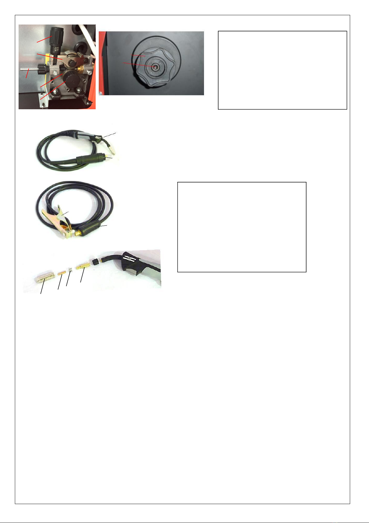
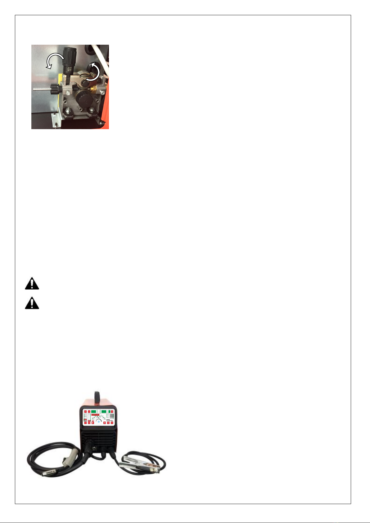
5.1.2.1 release the wire feeder tension arm(21) by pivoting the wire feed tension adjuster(20) as pictured below.
5.1.2.2 check the wire drive roller(23) groove matches the selected MIG wire type and size. The drive roller will have two
different sized grooves, the size of the groove in use is stamped on the side of the drive roller. For flux cored ‘soft’ wire,
such as that used in gasless MIG welding, the drive roller groove has a serrated profit. For solid ‘hard’ MIG wire, the roller
groove has a ‘v’ shaped profile.
5.1.2.3 the drive roller(23) is removed by threading the drive roller retainer(24) off in the anti-clockwise direction. Once
the correct drive roller profile is selected, re-fit the drive roller.
5.1.2.4 thread the MIG wire from the spool through the input guide tube(22), through the roller groove and into the
outlet guide tube.
5.1.2.5 Replace the tension arm (21) and the tension adjustment (20). Double check the wire has located correctly in
the drive roller groove.
5.1.2.6 Adjusting wire feed tension: this is accomplished by winding the knob on the wire tension adjustment arm (20).
Clockwise will increase tension, anti-clockwise will decrease tension. There is a numbered scale on the tensioner to
indicate the position. Ideal tension should be as little as possible, while maintaining a consistent wire feed with no drive
roller slippage. Check all other possible causes of slippage, such as; incorrect/ worn drive roller, worn/ damaged torch
consumables, blocked/ damaged torch feed liner, before increasing feed tension.
Warning! - Before changing the feed roller or wire spool, ensure that the mains power is switched off
Warning! - The use of excessive feed tension will cause rapid and premature wear of the drive roller, the support
bearing and the drive motor.
5.1.3 Setup for gasless MIG welding operation
5.1.3.1 Connect the MIG Torch Euro Connector (28) to the torch socket on the front of the welder (11). Secure by firmly
hand tightening the threaded collar on the MIG Torch Euro Connector clockwise.
5.1.3.2 Check that the correct flux cored, gasless wire, matching drive roller (23) and welding tip (32) are fitted.
5.1.3.3 Connect Torch Connection Power Lead (14) to the negative (-) welding output terminal (13).
5.1.3.4 Connect Earth Lead Quick Connector (30) to the positive (+) output welding terminal (12). See picture below.
5.1.3.5 Connect Earth Clamp (29) to the work piece. Contact with workpiece must be strong contact with clean, bare

10
metal, with no corrosion, paint or scale at the contact point.
5.1.4 Setup for gas shielded MIG welding operation
Note - Gas shielded MIG welding requires a shielding gas supply, gas regulator and gas shielded MIG wire. These
accessories are not supplied standard with the RW1500MP. Please contact your local Repco branch for details.
5.1.4.1 Connect the MIG Torch Euro Connector (28) to the torch socket on the front of the welder (11). Secure by firmly
hand tightening the threaded collar on the MIG Torch Euro Connector clockwise.
5.1.4.2 Check that the correct gas shielded wire, matching drive roller (23) and welding tip (32) are fitted.
5.1.4.3 Connect Torch Connection Power Lead (14) to the positive (+) welding output terminal (12).
5.1.4.4 Connect Earth Lead Quick Connector (30) to the negative (-) output welding terminal (13). See picture below.
5.1.4.5 Connect Earth Clamp (29) to the work piece. Contact with workpiece must be strong contact with clean, bare metal,
with no corrosion, paint or scale at the contact point.
5.1.4.6 Connect the gas regulator (optional) and gas line to the inlet on the rear panel (18). If the regulator is equipped
with a flow gauge, the flow should be set between 8 – 15 L/minute depending on application. If gas regulator is not
equipped with a flow gauge, adjust pressure so gas can just be heard coming out of the torch conical nozzle (31). It is
recommended that gas flow is checked again, just prior to starting weld This can be done by triggering the MIG torch with
the unit powered up.
5.1.5 Setup for MMA/STICK mode operation
Note - MMA/Stick Welding requires an MMA lead set.
5.1.5.1 Connect Electrode holder Quick Connector to the positive (+) welding output terminal (12).
5.1.6.2 Connect Earth Lead Quick Connector (30) to the negative (-) output welding terminal (13). See picture below.

11
1)
Note: Since the arc of MIG welding is much strong than that of MMA welding, please wear welding helmet and protective
clothing.
Connection of Shield Gas
Connect the CO2hose, which come from the wire feeder to the copper
nozzle of gas bottle. The gas supply system includes the gas bottle, the
air regulator and the gas hose, the heater cable should be inserted into
the socket of machine’s back, and use the hose clamp to tighten it to
prevent leaking or air-in, so that the welding spot is protected.
Please note:
1) Leakage of shielding gas affects the performance of arc welding.
2) Avoid the sun shine on the gas cylinder to eliminate the possible
explosion of gas cylinder due to the increasing pressure of gas
resulted from the heat.
3) It is extremely forbidden to knock at gas cylinder and lay the
cylinder horizontally.
4) Ensure no person is up against the regulator, before the gas
release or shut the gas output.
5) For MIG-250GW and MIG-250GF, insert the power supply plug of
the heater into the 36 VAC (5A) socket on the back panel of the
welding machine.
6) The gas output volume meter should be installed vertically to
ensure the precisely measuring.
7) Before the installation of gas regulator, release and shut the gas
for several time in order to remove the possible dust on the sieve
to avail the gas output.

12
6.Welding settings quick reference chart

13
Basic welding guide
MIG (GMAW/FCAW) Basic Welding Technique
Two different welding processes are covered in this section (GMAW and FCAW), with the intention providing the very basic
concepts in using the MIG mode of welding, where a welding gun is hand held, and the electrode (welding wire) is fed into
a weld puddle, and the arc is shielded by an inert welding grade shielding gas or inert welding grade shielding gas mixture.
GAS METAL ARC WELDING (GMAW): This process, also known as MIG welding, CO2 welding, Micro Wire Welding, short arc
welding, dip transfer welding, wire welding etc., is an electric arc welding process which fuses together the parts to be
welded by heating them with an arc between a solid continuous, consumable electrode and the work. Shielding is
obtained from an externally supplied welding grade shielding gas or welding grade shielding gas mixture. The process is
normally applied semi automatically; however, the and fairly thick steels, and some non-ferrous metals in all positions.
FLUX CORED ARC WELDING (FCAW): This is an electric arc welding process which fuses together the parts to be welded by
heating them with wan arc between a continuous flux filled electrode wire and the work. Shielding is obtained through
decomposition of the flux within the tubular wire. Additional shielding may or may not be obtained from an externally
supplied gas or gas mixture. The process is normally applied semi automatically; however, the process may be applied
automatically or by machine. It is commonly used to weld large diameter electrodes in the flat and horizontal position and
small electrode diameters in all positions. The process is used to a lesser degree for welding stainless steel and for overlay
work.

14
Position of MIG Torch
The angle of MIG torch to the weld has an effect on the width of the weld.
The welding gun should be held at an angle to the weld joint. (See Secondary Adjustment Variables below) Hold the gun
so that the welding seam is viewed at all times. Always wear the welding helmet with proper filter lenses and use the
proper safety equipment.
CAUTION
Do not pull the welding gun back when the arc is established. This will create excessive wire extension (stick-out) and
make a very poor weld.
The electrode wire is not energized until the gun trigger switch is depressed. The wire may therefore be placed on the
seam or joint prior to lowering the helmet.

15
Distance from the MIG Torch Nozzle to the Work Piece
The electrode wire stick out from the MIG Torch nozzle should be between 10mm to 20.0mm. This distance may vary
depending on the type of joint that is being welded.
Travel Speed
The speed at which the molten pool travels influences the width of the weld and penetration of the welding run
MIG Welding (GMAW) Variables
Most of the welding done by all processes is on carbon steel. The items below describe the welding.
variables in short-arc welding of 24gauge (0.024”, 0.6mm) to ¼” (6.4mm) mild sheet or plate. The applied techniques
and end results in the GMAW process are controlled by these variables.
Preselected Variables
Preselected variables depend upon the type of material being welded, the thickness of the material, the welding position,
the deposition rate and the mechanical properties. These variables are:
Type of electrode wire
Size of electrode wire
Type of gas (not applicable to self-shielding wires FCAW)
Gas flow rate (not applicable to self-shielding wires FCAW)
Primary Adjustable Variables
These control the process after preselected variables have been found. They control the penetration, bead width, bead
height, arc stability, deposition rate and weld soundness. They are:
Arc Voltage
Welding current (wire feed speed)
Travel speed
Secondary Adjustable Variables
These variables cause changes in primary adjustable variables which in turn cause the desired change in the bead
formation. They are:
1.Stick-out (distance between the end of the contact tube (tip) and the end of the electrode wire). Maintain at about
10mm stick-out.
2. Wire Feed Speed. Increase in wire feed speed increases weld current, Decrease in wire feed speed decreases weld
current.
3. Nozzle Angle. This refers to the position of the welding gun in relation to the joint. The transverse angle is usually one
half the included angle between plates forming the joint. The longitudinal angle is the angle between the center line of
the welding gun and a line perpendicular to the axis of the weld. The longitudinal angle is generally called the Nozzle
Angle and can be either trailing (pulling) or leading (pushing). Whether the operator is left handed or right handed has to
be considered to realize the effects of each angle in relation to the direction of travel.

16
Establishing the Arc and Making Weld Beads
Before attempting to weld on a finished piece of work, it is recommended that practice welds be made on a sample
metal of the same material as that of the finished piece.
The easiest welding procedure for the beginner to experiment with MIG welding is the flat position. The equipment is
capable of flat, vertical and overhead positions.
For practicing MIG welding, secure some pieces of 16 or 18 gauge (0.06” 1.5mm or 0.08” 2.0mm) mild steel plate 6” x 6”
(150 x 150mm). Use 0.030” (0.8mm) flux cored gasless wire or a solid wire with shielding gas.
Setting of the Power Source
Power source and wirefeeder setting requires some practice by the operator, as the welding plant has two control settings
that have to balance. These are the wirespeed control and the welding voltage Control. The welding current is determined
by the wirespeed control, the current will increase with increase wirespeed, resulting in a shorter arc. Less wire speed will
reduce the current and lengthen the increasing the welding voltage hardly alters the current level, but lengthens the arc.
By decreasing voltage, a shorter arc is obtained with a little change in current level.
When changing to a different electrode wire diameter, different control settings are required. A thinner electrode wire
needs more wirespeed to achieve the same current level
A satisfactory weld cannot be obtained if the wirespeed and voltage settings are not adjusted to suit the electrode wire
diameter and the dimensions of the work piece.
If the wirespeed is too high for the welding voltage, “stubbing” will occur as the wire dips into the molten pool and does
not melt. Welding in these conditions normally produces a poor weld due to lack of fusion. If, however, the welding
voltage is too high, large drops will form on the end of the wire, causing spatter. The correct setting of voltage and
wirespeed can be seen in the shape of the weld deposit and heard by a smooth regular arc sound. Refer to the Weld Guide
located on the inside of the wirefeed compartment door for setup information.
Electrode Wire Size Selection
The choice of Electrode wire size and shielding gas used depends on the following:
Thickness of the metal to be welded
Capacity of the wire feed unit and Power Source
The amount of penetration required
The deposition rate required
The bead profile desired
The position of welding
Cost of the wire

17
7.Range of welding current and voltage in CO2welding
-The option of the welding speed
The welding quality and productivity should be taken into consideration for the option of welding speed. In case that the
welding speed increases, it weakens the protection efficiency and speeds up the cooling process. As a consequence, it is
not optimal for the seaming. In the event that the speed is too slow, the work piece will be easily damaged, and the
seaming is not ideal. In practical operation, the welding speed should not exceed 1m/min.
-The length of wire stretching out
The length of wire stretching out the nozzle should be appropriate. The increase of the length of wire stretching out of the
nozzle can improve the productivity, but if it is too long, excessive spatter will occur in the welding process. Generally, the
length of wire stretching out the nozzle should be 10 times as the welding wire diameter.
-The setting of the C02flow volume
The protection efficiency is the primary consideration. Besides, inner-angle welding has better protection efficiency than
external-angel welding. For the main parameter, refer to the following figure.
Option of C02flow volume
Welding mode
Thin wire C02welding
Thick wire C02welding
Thick wire, big current
C02welding
C02(L/min)
5~15
15~25
25~50
8.WELDING PARAMETERS TABLE
The option of the welding current and welding voltage directly influences the welding stability, welding quality and
productivity. In order to obtain the good welding quality, the welding current and welding voltage should be set optimally.
Generally, the setting of weld condition should be according to the welding diameter and the melting form as well as the
production requirement.
The following parameter is available for reference.
Parameter for butt-welding (Please refer to the following figure.)
Plate
thickness
t(mm)
Gap
g(mm)
Wire
φ(mm)
Welding
current(A)
Welding voltage
(V)
Welding speed
(cm/min)
Gas
volume
(L/min)
0.8
0
0.8~0.9
60~70
16~16.5
50~60
10
1.0
0
0.8~0.9
75~85
17~17.5
50~60
10~15
1.2
0
1.0
70~80
17~18
45~55
10
Wire φ(mm)
Short circuit transition
Granular transition
Current(A)
Voltage (V)
Current(A)
Voltage (V)
0.6
40~70
17~19
160~400
25~38
0.8
60~100
18~19
200~500
26~40
1.0
80~120
18~21
200~600
27~40

18
1.6
0
1.0
80~100
18~19
45~55
10~15
2.0
0~0.5
1.0
100~110
19~20
40~55
10~15
2.3
0.5~1.0
1.0 or 1.2
110~130
19~20
50~55
10~15
3.2
1.0~1.2
1.0 or 1.2
130~150
19~21
40~50
10~15
4.5
1.2~1.5
1.2
150~170
21~23
40~50
10~15
Gasless
2.3
0.5~1.0
0.8/1.0
110~130
14~16
30~40/20~30
\
3.2
1.0~1.2
0.8/1.0
130~150
15~17
50~60/40~50
\
4.5
1.2~1.5
0.8/1.0
150~190
16~18
60~70/50~60
\
Parameter for flat fillet welding (Please refer to the following figure.)
Plate thickness
t(mm)
Corn size
I (mm)
Wire
φ(mm)
Welding
current
(A)
Welding
voltage
(V)
Welding speed
(cm/min)
Gas volume
(L/min)
1.0
2.5~3.0
0.8~0.9
70~80
17~18
50~60
10~15
1.2
2.5~3.0
1.0
70~100
18~19
50~60
10~15
1.6
2.5~3.0
1.0 ~ 1.2
90~120
18~20
50~60
10~15
2.0
3.0~3.5
1.0 ~ 1.2
100~130
19~20
50~60
10~20
2.3
2.5~3.0
1.0 ~ 1.2
120~140
19~21
50~60
10~20
3.2
3.0~4.0
1.0 ~ 1.2
130~170
19~21
45~55
10~20
4.5
4.0~4.5
1.2
190~230
22~24
45~55
10~20
Gasless
2.3
2.5~3.0
0.8/1.0
120~140
14~16
30~40/20~30
\
3.2
3.0~4.0
0.8/1.0
140~160
15~17
50~60/40~50
\
4.5
4.0~4.5
0.8/1.0
150~190
16~18
60~70/50~60
\
Parameter for fillet welding in the vertical position (Please refer to the following figure.)
Plate
thickness
t(mm)
Corn size
I (mm)
Wire
φ(mm)
Welding
current
(A)
Welding
voltage
(V)
Welding
speed
(cm/min)
Gas volume
(L/min)

19
1.2
2.5~3.0
1.0
70~100
18~19
50~60
10~15
1.6
2.5~3.0
1.0 ~ 1.2
90~120
18~20
50~60
10~15
2.0
3.0~3.5
1.0 ~ 1.2
100~130
19~20
50~60
10~20
2.3
3.0~3.5
1.0 ~ 1.2
120~140
19~21
50~60
10~20
3.2
3.0~4.0
1.0 ~ 1.2
130~170
22~22
45~55
10~20
4.5
4.0~4.5
1.2
200~250
23~26
45~55
10~20
Gasless
2.3
0.5~1.0
0.8/1.0
120~140
14~16
30~40/20~30
\
3.2
1.0~1.2
0.8/1.0
140~160
15~17
50~60/40~50
\
4.5
1.2~1.5
0.8/1.0
150~190
16~18
60~70/50~60
\
Parameter for Lap Welding (Please refer to the following figure.)
Plate
thickness
t(mm)
Welding
position
Wire
φ(mm)
Welding
current
(A)
Welding
voltage
(V)
Welding speed
(cm/min)
Gas volume
(L/min)
0.8
A
0.8~0.9
60~70
16~17
40~45
10~15
1.2
A
1.0
80~100
18~19
45~55
10~15
1.6
A
1.0 ~ 1.2
100~120
18~20
45~55
10~15
2.0
A or B
1.0 ~ 1.2
100~130
18~20
45~55
15~20
2.3
B
1.0 ~ 1.2
120~140
19~21
45~50
15~20
3.2
B
1.0 ~ 1.2
130~160
19~22
45~50
15~20
4.5
B
1.2
150~200
21~24
40~45
15~20
Gasless
2.3
B
0.8/1.0
120~140
14~16
30~40/20~30
\
3.2
B
0.8/1.0
140~160
15~17
50~60/40~50
\
4.5
B
0.8/1.0
150~190
16~18
60~70/50~60
\
Table of contents
Other ANDELI Welding System manuals
Popular Welding System manuals by other brands

Miller Electric
Miller Electric Millermatic Passport Plus owner's manual

Lincoln Electric
Lincoln Electric 9919 Operator's manual

Deca
Deca Domus 171E instruction manual

Thermal Arc
Thermal Arc EXCEL-ARC 750 CC owner's manual

bester
bester PDE 50 Operator's manual

Image Industries
Image Industries CD 110 Operation manual

ESAB
ESAB POWERCUT-1500 instruction manual

Draper
Draper acdc160p instruction manual

Lincoln Electric
Lincoln Electric RANGER SVM120-A Service manual

Lincoln Electric
Lincoln Electric Invertec 135S Operator's manual

ESAB
ESAB Aristo Mig C3000i instruction manual

Clarke
Clarke 195TEC Operating & maintenance instructions