Alfa Plam ALFA TERM 20 PELET User manual

17500 VRANJE, SERBIA
1, Radnička Street, Tel.: 017/421-121
USER INSTRUCTIONS
CENTRAL HEATING PELLET BURNING COOKER
„ALFA TERM 20 PELET”
Pellets →wood biomass fuel →biofuel
COOKER INSTALLATION, USE AND MAINTENANCE INSTRUCTIONS
ENG-V.1.0

0.0. TECHNICAL CHARACTERISTICS OF THE COOKER „ALFA TERM 20
PELET”
1. Cooker dimensions:
- width 1100 mm
- depth 600 mm
- height 850 mm
2. Diameter of the flue connection 80/100 mm
3. Diameter of the air inlet opening on the outer wall 100 mm
4. Height from the floor to the axis of the flue connection 690 mm
5. Rated power of the cooker 20 KW
6. Heat radiation of the cooker at nominal power 4,8 KW
7. Heat transferred to water at nominal power 15,2 KW
8. Maximum consumption 4,75 kg/h
9. Utilization degree at maximum power 87,1 %
10. Minimum power of the cooker 5,8KW
11. Heat radiation of the cooker at minimum power 1,5 KW
12. Heat transferred to water at minimum power 4,3KW
13. Minimum consumption 1,32 kg/h
14. Utilization degree at minimum power 91,9%
15. Minimum draft 10Pa
16. Optimum draft 14Pa
17. Heating capacity 275 - 350 m3
18. Fuel storage capacity 30 kg
19. Maximum operating time with full storage 20h
20. Minimum operating time with full storage 6,4 h
21. Maximum output power 370 W
22. Voltage and frequency 230V / 50Hz
23. Cooker weight:
- net 210kg
- gross 238kg
24. CO2 emission (13% O2) at nominal heat output 0,020%
25. CO2 emission (13% O2) at minimum heat output 0,020%
26. Mass flow-rate of flue gases at nominal heat output 17,6g/sec
27. Mass flow-rate of flue gases at minimum heat output 8,7g/sec
28. Temperature of flue gases at nominal heat output 182oC
29. Temperature of flue gases at minimum heat output 81oC
30. Water content in the boiler 35 litara
31. Maximum operating pressure 2bar.
Dear buyer,
We thank you for choosing and buying our appliance, in which we have invested a great effort so you could be satisfied with
its use.
We are sure that you have chosen a high-quality and economical appliance, which is the result of many years of experience
in this factory in the production of household appliances. This appliance has been designed and tested in accordance with the
safety standards of the applicable EU regulations.
Before installing and using the appliance, please read this manual carefully and adhere to all the advices included in it, as
this will result in proper state and constant readiness of the appliance for proper operation, as well as long service life.
Should any malfunction occur on the appliance, it is necessary to contact our nearest Customer Service for professional
assistance and repair. The addresses and phone numbers of our Customer Service offices are given at the end of the manual.
Keep these instructions, because it can also be of use to you in many situations in the future.
If you sell the appliance, give these instructions to your buyer.
In case of any ambiguities, please contact our professional services or an authorized service center. Always indicate the
number of chapter containing those ambiguities.
Printing, translation and reproduction of these instructions, in whole or in part, are prohibited without the permission of ALFA
PLAM. Technical information, pictures and specifications contained in these instructions must not be given to a third party.
List of content:

1. INTRODUCTION ............................................................................................................................................................... 1
1.1. PURPOSE................................................................................................................................................................. 1
1.2. PURPOSE AND CONTENT OF INSTRUCTIONS ........................................................................................................... 1
1.3. UPDATING THE INSTRUCTIONS................................................................................................................................ 1
1.4. GENERAL ................................................................................................................................................................. 1
1.5. LEGAL WARRANTY................................................................................................................................................... 1
1.6. RESPONSIBILITY OF THE MANUFACTURER .............................................................................................................. 1
1.7. CHARACTERISTICS OF THE USER............................................................................................................................. 2
1.8. TECHNICAL ASSISTANCE ......................................................................................................................................... 2
1.9. SPARE PARTS .......................................................................................................................................................... 2
1.10. RATING PLATE ..................................................................................................................................................... 2
1.11. DELIVERY OF THE COOKER .................................................................................................................................. 2
2. SAFETY WARNINGS ......................................................................................................................................................... 2
2.1. WARNINGS FOR INSTALLER..................................................................................................................................... 2
2.2. WARNINGS FOR USER.............................................................................................................................................. 2
2.3. WARNINGS FOR A MAINTENANCE WORKER ............................................................................................................. 3
3. FUEL CHARACTERISTICS AND DESCRIPTION OF THE COOKER ......................................................................................... 3
3.1 FUEL CHARACTERISTICS.......................................................................................................................................... 3
3.2. PELLETS STORAGE .................................................................................................................................................. 3
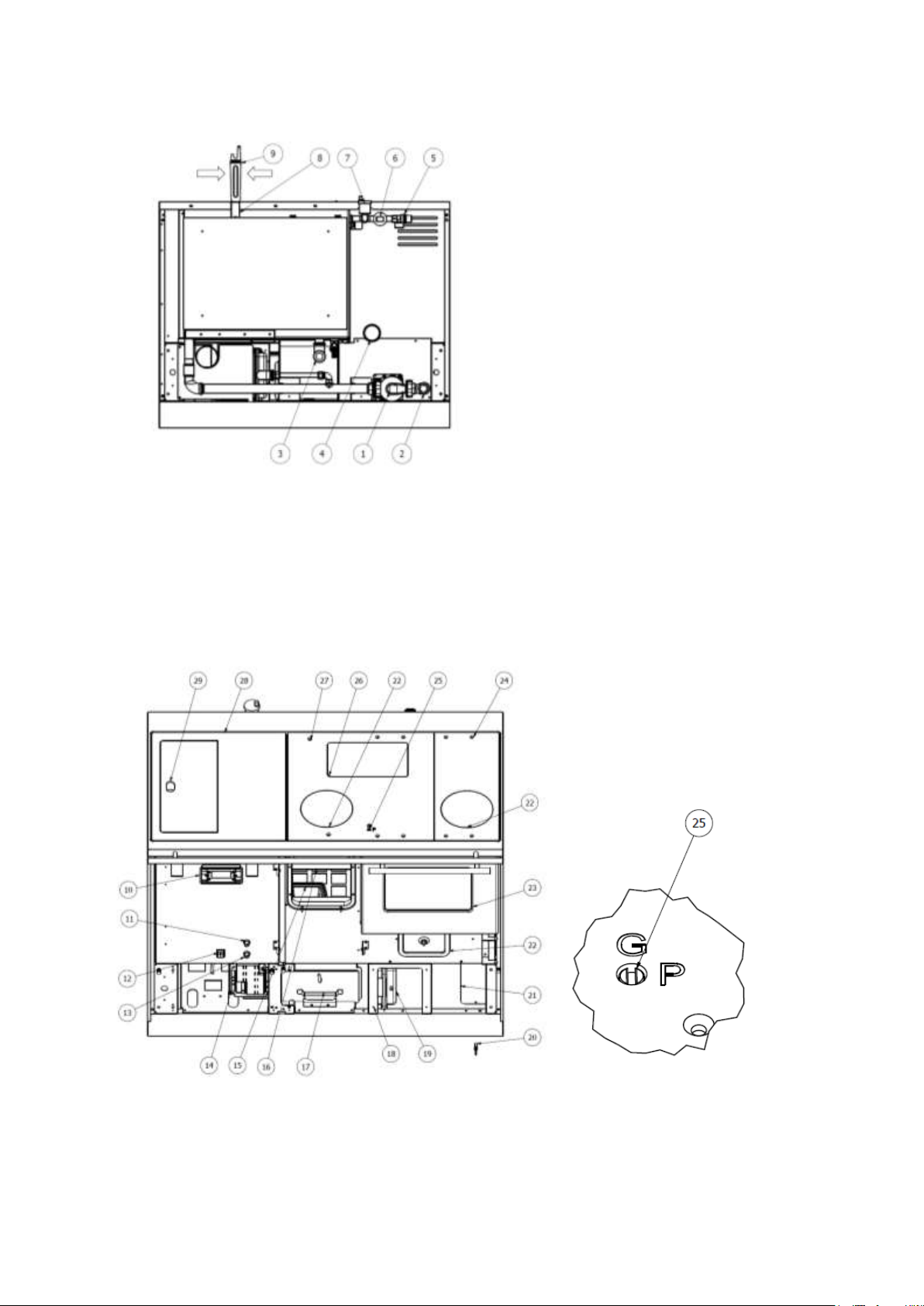
3.3. MAIN PARTS OF THE COOKER.................................................................................................................................. 4
3.4. DIMENSIONS OF THE COOKER ................................................................................................................................. 5
4. MOVING AND TRANSPORT .............................................................................................................................................. 5
5. PREPARATION OF THE SPACE FOR INSTALLATION .......................................................................................................... 5
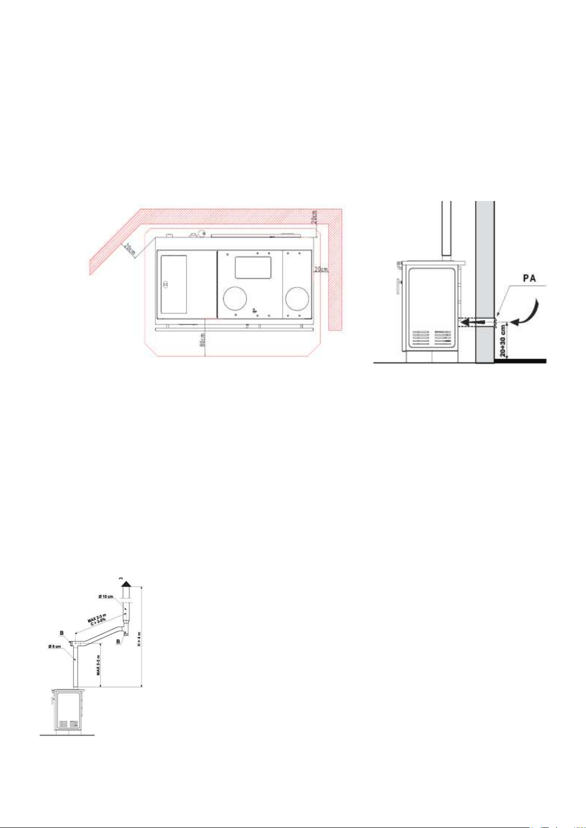
5.1. PRECAUTIONARY MEASURES .................................................................................................................................. 5
5.2. GENERAL MEASURES............................................................................................................................................... 5
5.3. LOCATION OF INSTALLATION OF THE COOKER ........................................................................................................ 6
5.4. AIR USED FOR COMBUSTION ................................................................................................................................... 6
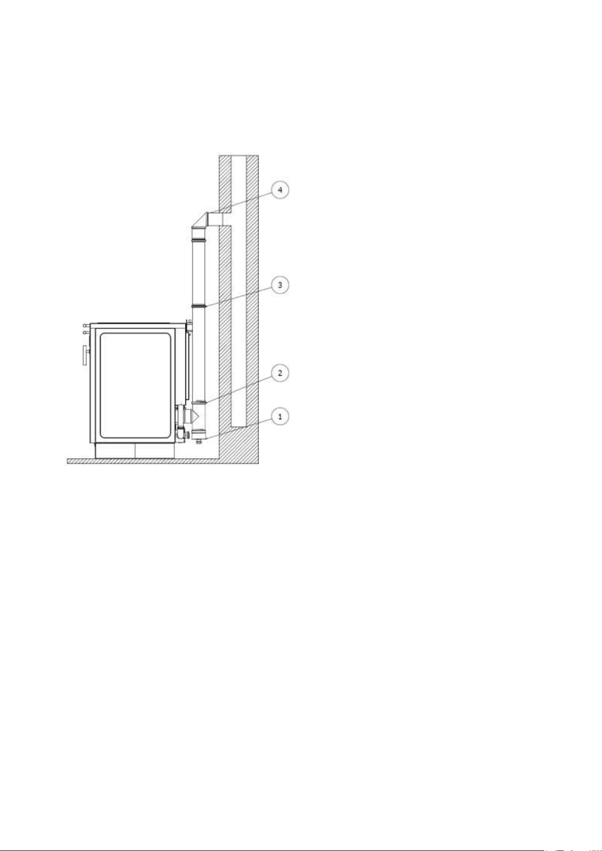
5.5. SMOKE EXTRACTION ............................................................................................................................................... 7
5.6. AIR USED FOR COMBUSTION ................................................................................................................................... 8
6. INSTALLING..................................................................................................................................................................... 2
6.1. SAFETY MEASURES FOR MAINTENANCE PERSONNEL.............................................................................................. 2
6.2. SAFETY MEASURES FOR USERS............................................................................................................................... 2
7. INSTRUCTIONS FOR SAFE TURNING ON AND CLEANING THE COOKER............................................................................. 3
7.1. REGULAR CLEANING AND MAINTENANCE PERFORMED BY THE USER OF THE COOKER............................................ 3
7.2. SPECIAL MAINTENANCE .......................................................................................................................................... 5
8. IMPORTANT SAFETY INFORMATION................................................................................................................................ 5
9. CHOOSING PELLETS........................................................................................................................................................ 6
9.1. PELLETS STORAGE .................................................................................................................................................. 6
10. CONNECTING HYDRAULIC INSTALLATION.................................................................................................................... 6
10.1. PRESSURE AND RETURN LINE.............................................................................................................................. 7
10.2. COOKER EMBEDDED COMPONENTS..................................................................................................................... 7
10.3. SAFETY VALVE (Figure 18, Position 6)................................................................................................................. 7
10.4. CIRCULATION PUMP (Figure 18, Position 1) ......................................................................................................... 7
10.5. AUTOMATIC AIR-BLEEDING VALVE (Figure 18, Position 8) ................................................................................... 7
10.6. EXPANSION VESSEL (Figure 18, Position 2) ......................................................................................................... 8
10.7. TAP FOR FILLING AND DISCHARGING (Figure 18, Position 9)................................................................................ 8
10.8. WATER PRESSURE SENSOR (Figure 18, Position 7) .............................................................................................. 8
11. FILLING THE INSTALLATIONS AND COMMISSIONING................................................................................................... 8
12. TIPS FOR THE USE OF THE HEATING SYSTEM .............................................................................................................. 8
12.1. COOKING, BAKING/ROASTING AND FRYING ......................................................................................................... 8
13.FEEDING THE PELLETS INTO THE FUEL STORAGE ........................................................................................................ 8
14. CONTROL SYSTEM OF THE COOKER............................................................................................................................. 9
14.1. ELECTRIC CONNECTIONS SCHEME ...................................................................................................................... 9
14.2. CONTROL PANEL (DISPLAY) - BUTTONS AND FUNCTIONS................................................................................... 9
14.3. MENU ................................................................................................................................................................ 11
14.3.1. COMBUSTION MANAGEMENT MENU ......................................................................................................... 12
14.3.2. HEATING MANAGEMENT MENU ................................................................................................................. 13
14.3.3. CHRONO MENU ......................................................................................................................................... 14
14.3.4. MANUAL PELLETS LOADING MENU ........................................................................................................... 15
14.3.5. MANUAL LOADING MENU .......................................................................................................................... 16
14.3.6. TIME AND DATE MENU .............................................................................................................................. 16
14.3.7. REMOTE CONTROL MENU.......................................................................................................................... 16
14.3.8. LANGUAGE SELECTION MENU ................................................................................................................... 16
14.3.9. DISPLAY MENU ......................................................................................................................................... 16
14.3.10. SYSTEM MENU.......................................................................................................................................... 16
14.4. COOKER IGNITION AND FUNCTIONAL CONDITIONS............................................................................................ 16
14.5. POSSIBLE PROBLEMS AND SOLUTIONS............................................................................................................. 18
15. SAFETY MEASURES.................................................................................................................................................... 19
16. FAULTS - CAUSES - SOLUTIONS ................................................................................................................................ 20
17. INFORMATION ON DISPOSAL AND DISASSEMBLING THE COOKER ............................................................................. 21

1
1. INTRODUCTION
The purpose of these instructions is to enable the user to take all necessary measures to ensure the safe and proper use of
the cooker.
ALFA PLAM reserves the right to change the specifications and technical and/or functional characteristics of the cooker at
any time, without prior notice.
1.1. PURPOSE
The pellet burning cooker is intended for heating the living space. The cooker provides direct heating of the room in which it
is installed and does not require additional heating bodies (radiators), because it uniformly heats the room through radiation and
convection. The cooker operates only with firebox door closed. Never open the door during operation of the cooker.
The cooker is characterized by double combustion system, PRIMARY and SECONDARY, with positive effects both in terms of
performance, and in terms of cleaner combustion products.
The stated purpose and the intended configurations of the cooker are the only ones allowed by the manufacturer: use the
cooker only in accordance with these instructions.
ALFA PLAM cooker is an appliance that can be used only indoors.
1.2. PURPOSE AND CONTENT OF INSTRUCTIONS
The purpose of the instructions is to enable the user to take all necessary measures in order to achieve safe and proper use
of the cooker. These instructions contain all the necessary information on installation, use and maintenance of the cooker.
Conscientious compliance with the guidelines from the instructions guarantees a high degree of safety and performance of the
cooker. The instructions must be carefully kept and must always be available for consultation, both by the user and by
personnel in charge of assembly and maintenance. Use and maintenance instructions are an integral part of the cooker. In the
event of losing the instructions, ask ALFA PLAM for another copy.
In the case of sale of the cooker, the user is obliged to submit these instructions to the new buyer.
1.3. UPDATING THE INSTRUCTIONS
These instructions correspond to the technical level of knowledge at the moment of introduction of the cooker to the market.
ALFA PLAM will not consider other cookers that are already present on the market, with the appropriate technical
documentation, as incomplete or inadequate in case of possible changes, adjustments or application of new technologies on
newly manufactured cookers.
1.4. GENERAL
INFORMATION
When contacting the cooker manufacturer, it is necessary to note the serial number and identification data listed on the page
“GENERAL” at the end of these instructions.
RESPONSIBILITY
The company ALFA PLAM accepts no liability for any material damage or injuries occurred due to:
- disregarding the advices and warnings given in these instructions,
- improper use of the cooker by the user,
- modifications and repairs not approved by ALFA PLAM,
- poor maintenance,
- unforeseen events,
- use of spare parts that are not original or not intended for these models of the cooker.
The installer takes the full responsibility for connections of the cooker.
EXTRAORDINARY MAINTENANCE
Extraordinary maintenance must be carried out by personnel qualified for intervention on the cooker model to which these
instructions apply.
USE
When using the cooker, the advices given in these instructions and all national regulations of the country where the cooker is
installed is to be followed.
1.5. LEGAL WARRANTY
In order to be able to use a legal warranty in accordance with CEE 1994/44/CE, the user must strictly adhere to the
allegations contained in these instructions, and in particular:
- to use the cooker in accordance with its intended purpose,
- to maintain it regularly and carefully,
- to authorize persons with sufficient abilities, responsibility and technical knowledge, for the use of the cooker.
Failure to observe the advices given in these instructions will result in a loss of warranty.
1.6. RESPONSIBILITY OF THE MANUFACTURER
The manufacturer does not accept any civil or criminal liability, direct or indirect, in the event of:
- installations that do not comply with applicable national regulations in the country of installation, and with safety
recommendations,
- disregard of the advices and warnings given in these instructions,

2
- installation performed by unqualified and unskilled personnel,
- use that is not in accordance with the safety recommendations from the instructions,
- made changes and repairs for which no authorization has been obtained from the manufacturer,
- use of spare parts that are not genuine or not intended for this model of cooker,
- poor maintenance of the cooker,
- unforeseen events.
1.7. CHARACTERISTICS OF THE USER
The user of the cooker must be an adult and responsible person with technical knowledge necessary for regular
maintenance of mechanical and electrical parts of the cooker.
Take care that children do not approach the cooker while in operation, with the intention to play.
Children should not approach the cooker while in operation with the intention to play. This appliance can be used by children
aged 8 and over and persons with reduced physical, sensory or mental capacity, if they are supervised by an elderly person
familiar with the instructions for use. Cleaning and maintenance of the cooker cannot be carried out by children without
supervision of the elderly person.
1.8. TECHNICAL ASSISTANCE
The company ALFA PLAM is able to solve any technical problem related to the use and maintenance of the cooker
throughout its lifetime.
The Technical Support Service is at your disposal for any questions and, if necessary, to refer you to the nearest authorized
service.
1.9. SPARE PARTS
Use only original spare parts. Do not wait for parts to wear out before their replacement. Replacing the damaged piece before
its breaking prevents possible accidents that arise precisely because of sudden breaking of parts, which can cause injuries to
people and cause damage to things. Carry out periodic maintenance controls as described in the chapter “MAINTENANCE AND
CLEANING”.
1.10. RATING PLATE
The rating plate on the cooker contains all product-related characteristics, including manufacturer information, serial
number and CE marking.
1.11. DELIVERY OF THE COOKER
The cooker is delivered in wooden packaging. It is attached to the wooden stand, which provides its stability when moved
with forklift and/or other means. The inside of the cooker contains the following material:
- instructions for use, installation and maintenance,
- blade for cleaning the cooker (channels through which the smoke passes),
- special key
- glove.
2. SAFETY WARNINGS
2.1. WARNINGS FOR INSTALLER
- verify whether the cooker characteristics are in accordance with local, national and European regulations,
- comply with the notes from these instructions,
- check that the volume of the room in which the cooker is installed is adequate,
- verify whether the requirements from the manufacturer's instructions regarding the smoke extraction system have been
met,
- check the internal cross-section of the chimney, the material from which the chimney is made, the uniformity of the cross-
section, and whether there are any obstacles in the chimney,
- check the height and vertical extension of the chimney,
- check the possibility of providing the supply of external air and the size of the required openings,
- check the possibility of simultaneous use of the cooker, which is to be connected, with other appliances and devices, if
such already exist at that location,
- always provide sufficient space for servicing required for any kind of maintenance and repair of the cooker,
- do not use bare electrical connections with temporary and non-insulated cables,
- check whether the grounding of the electrical appliance is effective,
- always use personal protective equipment and other protective equipment prescribed by the law.
2.2. WARNINGS FOR USER
- Prepare the space for the installation of the cooker in accordance with local, national and European regulations,
- The cooker, since it is a heating body, has a very warm outside surface and therefore it is recommended to be very careful
while its operation, in particular:
do not touch and approach the glass on the door and oven; it can cause burns,
do not touch the pipe through which smoke passes,
do not perform any cleaning,

3
do not open the firebox door,
ensure that children do not approach the cooker,
if the power cable is damaged, it must be replaced by the manufacturer (its authorized service technician) or by a
qualified person in order to avoid danger.
- Observe the notes from these instructions,
- Observe the notes and warnings on the plates placed on the cooker,
- Plates contain instructions for preventing accidents at work, therefore they must always be completely legible.
Should they be damaged or become illegible, be sure to replace them, asking the manufacturer for the genuine replacement.
- Use only fuel corresponding to the instructions from the chapter relating to the characteristics of the fuel itself,
- Strictly adhere to the periodic and extraordinary maintenance plan,
- Do not turn on the cooker without previous daily control performed in the manner specified in the section “Maintenance”
of these instructions,
- Do not use the cooker in case of improper operation, in the event of any doubt that something has been broken, or in the
case
of unusual sounds,
- Do not spray or spill water on the cooker, even when extinguishing the fire,
- Do not turn off the cooker by unplugging from the socket - it may jeopardize the proper operation of the cooker,
- Do not use the cooker as a support or for anchoring of any kind,
- Do not lean on the open cooker, its stability may be compromised,
- Do not clean the cooker before it is completely cooled down as well as the ash,
- Touch the door only when the cooker is cold,
- Conduct all operations with full attention even in the conditions of maximum safety,
- In case of a fire in the chimney, turn off the cooker in the manner prescribed for fire fighting and call firefighters,
- In the case of poor operation of the cooker caused by a weak draft, clean the chimney,
- Cleaning of chimney must be performed at least twice a year,
- Do not touch the painted parts during operation of the cooker in order to avoid possible burns,
- Fuse replacement is performed by qualified personnel.
CAUTION: In order to avoid any hazard caused by accidentally switching on the thermal switch, this cooker must not be
powered by an external control device, such as a timer, but must be connected to a circuit that is regularly powered and
disconnected from the network.
2.3. WARNINGS FOR A MAINTENANCE WORKER
- Always use personal protective equipment and other protective equipment.
- Before starting any kind of maintenance, make sure that the cooker, if already used, is cooled down.
- DO NOT TURN THE COOKER ON even if only one of the safety devices is faulty, improperly set or not operating.
- Remove the plug from the wall socket before work on electrical and electronic components and connectors.
3. FUEL CHARACTERISTICS AND DESCRIPTION OF THE COOKER
3.1 FUEL CHARACTERISTICS
- Pellet is a fuel of cylindrical shape, produced from different types of wood, mechanically pressed, in compliance with the
regulations on environmental protection.
It is the only type of fuel envisaged for this type of cooker.
- The efficiency and thermal power of the cooker may vary depending on the type and quality of the wood pellets used.
- Burning of different types of pellets may require modification or adjustment of program settings.
In order for the cooker to work properly, the pellets must have the following characteristics:
- diameter Ø 6 mm
- maximum length 30 mm
- maximum moisture content 8% to 9%
The cooker is equipped with a pellet storage with the capacity specified in the table of technical characteristics.
The storage cover is on the upper side of the cooker.
The proper operation of the cooker depends on the type and quality of pellets, since the heat obtained from the different
types of pellets can be of different intensity.
The manufacturer of the cooker does not bear any responsibility for poor operation of the cooker in the case of use of pellets
of inadequate quality.
It is forbidden to use the cooker for incinerating waste.
3.2. PELLETS STORAGE
Pellets must be stored in a dry and well-ventilated room, at a temperature of 10˚C ÷ 25˚C. A cool and moist pellet stored in a
humid room, with temperature below 5˚C, has reduced thermal power and requires additional cleaning of the cooker.
PELLETS CAN NOT BE KEPT AT A DISTANCE OF LESS THAN 2 METERS FROM THE COOKER. Handle pellets carefully, do not
break it.
WARNING: If a sawdust or small (broken) pellets are fed in the fuel storage, it may block the pellet insertion. Such pellets
may lead to burnout of the electric motor that drives the pellet insertion mechanism, or to damage of the gear unit that works in
conjunction with the electric motor. If you notice such pellets at the bottom of the pellets storage, that is, at the bottom of the
auger when the storage is empty, vacuum it with a vacuum cleaner by dragging the vacuum cleaner pipe through the openings
of the storage grate.

4
It is advised that several pellet bags are kept in a room where the cooker is used, or in the adjacent room due to acceptable
temperature and humidity.
Pay special attention to storing and moving the pellet bags. Its breaking and creating sawdust should be avoided.
3.3. MAIN PARTS OF THE COOKER
1. Circulation pump
2. Return line
3. Pressure line
4. Pipe for supplying air for combustion
5. Safety valve
6. Water pressure sensor
7. Air bleed vent
8. Lever of the flue pipes cleaning mechanism
9. Special key
10. Dashboard
11. Safety thermostat T = 80˚C
12. Switch
13. Safety thermostat T = 88˚C
14. Electronic plate
15. Casted firebox
16. Combustion chamber
17. Ashtray
18. Protection holder, small
19. Expansion vessel
20. Wing screw
21. Fan box cover
22. Lid for cleaning under the oven
23. Oven cover
24. Smoke chamber cover
25. Mode controller
26. Rectangular cleaning lid
27. Cooktop - middle part
28. Cooktop above the pellet storage
29. Storage cover
Figure 1
Figure 2

5
3.4. DIMENSIONS OF THE COOKER
Figure 3
4. MOVING AND TRANSPORT
The cooker is delivered with all the parts foreseen.
Be careful - the cooker has a tendency to overturn.
The cooker’s center of gravity is shifted to the left.
Take care of this even when moving the cooker.
When lifting, avoid sudden movements.
Make sure that the forklift truck has a load capacity greater than the weight of the cooker to be lifted.
The forklift operator will be solely responsible for raising the load.
Prevent children from playing with parts of packaging (for example: foils and polystyrene). Risk of choking!
5. PREPARATION OF THE SPACE FOR INSTALLATION
5.1. PRECAUTIONARY MEASURES
The responsibility for the work done at the point of installation is entirely on the user.
The user must comply with all local, national and European safety regulations.
The cooker must be set up on the floor of the appropriate load capacity.
Cooker assembly and disassembly instructions are exclusively intended for authorized installers.
The installer must, prior to commencing the assembly or disassembly stage of the cooker, implement the safety measures
prescribed by law, and in particular:
A) must not work in interfering conditions;
B) must verify that the personal protective equipment is complete and in good condition;
C) must wear protective gloves;
D) must wear protective shoes;
E) must use tools with electric shock insulation;
F) must ensure that the place where assembly or disassembly is carried out is free of obstacles.
5.2. GENERAL MEASURES
There are many factors that influence the efficiency of burning - in terms of thermal performance and low emissions of
contaminants (CO - carbon monoxide). Some factors depend on the cooker, but some depend on the characteristics of the
space, installation and the degree of regular maintenance of the product.
Some of the more important factors are:

6
-the amount of incoming air used for combustion;
-characteristics of the system for combustion products discharge;
-quality of pellets (humidity and dimensions).
In the following paragraphs, some notes are given that have to be observed in order to achieve the best performance of
the purchased product.
5.3. LOCATION OF INSTALLATION OF THE COOKER
Figure 3 lists the minimum distances that must be observed when setting up the cooker, regarding the materials and
inflammable objects.
Protect from heat radiation of the flame all the objects that could catch fire due to exposure to excessive heat.
Wooden floors or those made of flammable material must be protected by non-flammable material, for example sheet metal
with a thickness of 2-3 mm.
The cooker can be installed between the two walls.
The minimum distance to be applied between the cooker and walls must be 10-20 cm.
Any wooden beams placed above the cooker must be protected with non-flammable material.
If the previous conditions are not met, the cooker cannot be installed.
Figure 3 Figure 4
5.4. AIR USED FOR COMBUSTION
- The cooker takes the air during operation from the room where it is located.
- The outside air can be supplied directly through a tube of 80 mm diameter with a seal (Figure 4).
- The maximum length of the air supply pipe is 4.5 m with a maximum of 3 knees at 90˚.
- The air inlet hole must be set at a height of about 20-30 cm from the ground.
- One grid for continuous ventilation must be installed outside. In very windy areas exposed to rain and wind, protection
against rain and wind must be foreseen.
- Ensure that the air inlet is positioned so that it cannot be accidentally blocked.
- In case it is impossible to achieve a direct supply of external air through the wall behind the cooker (the wall is not outer),
an opening must be made on one of the outer walls of the space in which the cooker is located.
- If the room does not have outer walls, it is possible to make an outer opening in the adjacent room and provide constant
supply of air through a grid placed on a wall between these two rooms.
- If the cooker is placed in the room with air extraction grilles, or if it is placed in a room with already existing appliances that
take air from the room, always take care that the amount of air supply to the room is sufficient to ensure the safe operation of
the cooker and existing appliances.
It is forbidden to supply air for combustion from rooms where there are risks of fire, such as garages, warehouses, depots,
etc.
A - chimney cap
B - inspection opening
C - slope
H - height
- If one or more fans for the extraction of air (aspirators) are installed in the room where the
cooker is placed, it is necessary to check if the poor operation of the cooker is caused by the
insufficient air required for combustion.
Figure 5

7
5.5. SMOKE EXTRACTION
- The tubes to be used for smoke extraction must be rigid, made of aluminum sheet (at least 1.5 mm thick wall) or stainless
steel (at least 0.5 mm thick wall). For lengths up to 5m, use pipes of 80mm diameter, with seals, and for lengths greater than 5m,
pipes of 100mm diameter, with seals.
- It is advisable to insulate the pipes with insulating material (with a mineral wool of at least 2 cm thickness), or use steel
pipes with a double wall, where the first vertical part, if it is internal, does not have to have double layer.
- It is mandatory that the first vertical part has a length of at least 1.5 meters in order to guarantee proper smoke extraction.
- It is advised to make at most 5 to 6 changes of direction using knees of 45-90˚or T joints.
- Always use T joints with inspection openings for each horizontal or vertical change of direction of the flue pipe.
- Horizontal parts must not have a length greater than 2-3 m, with an inclination of at least 5%.
- Anchor pipes to walls.
Flue pipes MUST NOT BE CONNECTED:
- To a chimney used by other smoke generators (furnaces, fireplaces, etc.)
- To the air extraction system (aspirators, valves, etc.) even if it is connected by pipes.
It is forbidden to install valves for preventing the draft.
In case of length of the flue pipe greater than 5 meters or in the conditions of poor airflow (the presence of many curves,
inadequate ending of the outlet, etc.), the extraction of smoke might be inappropriate. In this case, it will be necessary to
change the operating parameters (extraction of smoke and feeding pellets) in order to adjust the cooker to the actual
characteristics of the chimney.
Contact technical support.
5.5.1 Smoke extraction through the roof chimney
The smoke extraction chimney must be constructed in compliance with the regulations, both in terms of dimensions and in
terms of materials used for its construction.
RUINED chimneys, made of inadequate material (fibrous cement, galvanized steel, etc... whose interior is not smooth and
porous) are inadequate and may impact proper operations of the cooker.
Smoke extraction through a traditional chimney (Figures 7 and 8) can be executed only if the following rules are observed:
- Check the condition of the chimney - in the case of an old chimney, its repair is advised by introducing a properly insulated
steel tube (mineral wool, vermiculite).
- Smoke can be taken directly into the chimney equipped with an inspection opening.
The smoke extraction system (chimney) made of metal pipes must be grounded in accordance with existing standards and
legal regulations.
This grounding must be independent of the cooker’s grounding.
When installing the flue pipes start with T-
branch (2), to which a condensate vessel with an outlet
for condensate (1) is mounted. Then install a flue pipe
(3) and penetrate the wall with an 90° elbow (4).

8
Figure 7 Figure 8
A) Shutter against wind
B) Chimney
C) Hermetic closure
D) Inspection opening
- In the case of a larger diameter chimney, it is
necessary to insert a properly insulated steel tube (with a
diameter corresponding to the chimney (Figure 8).
A) Vermiculite and/or mineral wool
B) Steel pipe
C) Cover panel
- Check whether the connection to the chimney in the
wall is well sealed
- Avoid contact with combustible material (wooden
beams, etc.) and secure its insulation with non-flammable
material.
5.6. AIR USED FOR COMBUSTION
The cooker, during operation, takes air through the
opening located on the rear right side of the cooker from the
room in which it is located.
The outside air supply point can be connected to the wall
opening through a pipe of 80 mm diameter with a gasket.
One grate for constant ventilation must be placed on the
outside; In very windy areas exposed to rain and wind,
adequate protection must be foreseen.
Ensure that the air intake opening is positioned so it
cannot be accidentally blocked.
In the event that it is impossible to achieve external air
intake through the wall behind the cooker (the wall is not
outer), an opening must be made on one of the outer walls of
the room in which the cooker is located.
If it is impossible to supply external air into the room, it is
possible to make an outer opening in the adjacent room, but
continuous communication through the transit grid must be
enabled. The cooker configured in this way is no longer
sealed from the space in which it is installed.
It is forbidden to take air from the garage, a warehouse
with a flammable material or from a place with a fire hazard.
If there are other heaters in the room and the cooker is
not sealed from the space in which it is installed, the air
intake opening must guarantee the amount of air necessary
for the operation of all the devices in the room.
If one or more fans for the extraction of air (aspirators)
are used in the room where the cooker is fitted, it is
necessary to ensure that poor operation of the cooker
caused by the insufficient air required for combustion does
not occur.

2
6. INSTALLING
The installer must follow the following instructions in order to properly install the cooker:
- Plug in the cooker into the socket with grounding. (Figure 9)
- Set the cooker switch to position 1. (Figure 10)
- Do not allow the presence of children and pets near the cooker.
- Use only pellets as fuel.
- Inform all users of possible risks and dangers and teach them how to handle the cooker.
- If the cooker is placed on a wooden floor, then it is advisable to isolate the stand on which it is positioned.
The cooker works with a combustion chamber with a sub-pressure. So make sure the smoke extractor is thermally sealed.
When commissioning for the first time, ensure ventilation of the room, as the applied corrosion protection may produce an
unpleasant odor and create smoke for a short time. That is normal and it stops after a short while.
Figure 9 Figure 10
6.1. SAFETY MEASURES FOR MAINTENANCE PERSONNEL
Maintenance installers, in addition to having to comply with all security measures, must:
- always use safety devices and personal protective equipment,
- disconnect the power supply before they start to work,
- always use an adequate tool,
- before starting any work on the cooker, make sure that it has cooled down and that the ash is cold. In particular, make sure
that the handles are cooled before you touch them.
- NEVER TURN THE COOKER ON if any of the security devices are defective, incorrectly set or not working.
- Do not perform any type of modification, for whatever reason, other than those allowed and recommended by the
manufacturer itself.
- Always use genuine spare parts. Never wait for the components to wear out before replacing them. Replacement of the
worn-out part, or component of the cooker before it brakes, contributes to preventing the occurrence of damage due to sudden
failure, which can cause serious consequences for people and/or property.
- Clean the firebox before turning the cooker on.
- Make sure there is no condensation. If condensation occurs, this indicates the water generated from the smoke cooling
process.
We recommend you to find possible causes in order to establish normal and correct operation of the cooker.
6.2. SAFETY MEASURES FOR USERS
The location of installation of the cooker must be prepared in accordance with local, national and European regulations.
This cooker is manufactured to burn fuel made of pressed wood (pellets diameter 6 mm, length up to 30 mm, maximum
humidity 8-9%).
ATTENTION: High temperatures are generated on external surfaces of the cooker during operation.
Therefore, it is important to pay attention to the following during operation of the cooker:
- do not approach and touch the glass on the firebox and oven door, there is a DANGER OF BURNS,
- do not approach and touch the smoke extraction pipe, there is a DANGER OF BURNS,
- do not perform any cleaning,
- do not open the firebox door when the cooker is operating properly, only when the chamber is sealed,
- do not remove ashes when the cooker is in operation,
- children and pets must stay away from the cooker,
- OBSERVE ALL ADVICES GIVEN IN THESE INSTRUCTIONS.

3
For proper use of the cooker it is necessary to:
- use only fuel that complies with the manufacturer's instructions,
- always comply with the cooker maintenance schedule,
- clean the cooker daily (only when the cooker and ashes are cold),
- do not use the cooker in the event of a malfunction or some irregularities in operation, in case of unusual sounds and/or if
you suspect a malfunction,
- do not spray or spill water on the cooker, even when extinguishing the fire,
- do not turn off the cooker by pulling out the plug. Use a switch,
- do not lean on the cooker, because it may not be stable enough and COULD TURNOVER,
- do not use the cooker as a support or holder. Never leave the fuel storage cover open.
- do not touch the painted parts of the cooker while it is in operation,
- do not use wood or coal as a fuel, but only pellets with the following characteristics: diameter 6 mm, maximum length 30
mm, maximum moisture content 8-9%,
- do not use the cooker to incinerate the waste,
- always perform all operations with maximum security measures applied.
7. INSTRUCTIONS FOR SAFE TURNING ON AND CLEANING THE
COOKER
- Never use petrol, petroleum or any other flammable liquid to start fire in the cooker. Keep these types of fluids away from
the cooker while it is in operation,
- Never turn on the cooker if the glass is damaged. Do not hit the glass or door in order to prevent damage,
- Do not open the firebox door to clean the glass. Clean the glass only when the cooker is cold, using a cotton cloth or paper
towels (cloths) and a glass cleaning agent,
- Make sure that the cooker is well secured to prevent any movement,
- Make sure that the ashtray is inserted and completely closed so that it is correctly set on the front of the cooker,
- Make sure that the firebox door is well closed while the cooker is in operation,
- With the vacuum cleaner remove ash from the cooker only when the cooker is completely cold,
- Never use abrasive cleaners on the surface of the cooker.
7.1. REGULAR CLEANING AND MAINTENANCE PERFORMED BY THE
USER OF THE COOKER
Regular cleaning and maintenance is a prerequisite for the proper and efficient operation of the cooker.
IMPORTANT: Clean the appliance only when the cooker and ashes are cold.
Using the ash vacuum cleaner can facilitate the cleaning of the cooker. The vacuum cleaner must have a filter that prevents
the ash and unburned pellets from being returned to the room where the cooker is located.
Before you start with regular maintenance, including cleaning, the following precautions should be taken:
- turn off the cooker from the power supply before you start doing any work,
- before starting any work, make sure that the cooker and ashes have cooled down,
- vacuum the ash from the combustion chamber every day,
- clean the firebox carefully every day (after each use) with the vacuum cleaner,
Always ensure that the cooker and ash are cold.
- Firebox (Figure 11) is a part of the cooker in which the pellets are burned. It is recommended to clean the firebox with the
vacuum cleaner after each use. Cleaning is done by taking the firebox out and cleaning it from ash, slag and unburned pellets.
After cleaning, return the firebox back and place it firmly in its place to ensure the safe operation of the cooker. The firebox must
be in a horizontal position, it must not be inclined! The gasket on the underside of the firebox must be in place and must not be
damaged.
If something is unclear to you, do not hesitate to call our authorized customer service for further information and
explanations. The manufacturer has no insight into the installation of the cooker and does not provide a warranty for the
installation and maintenance of the cooker.
The manufacturer does not assume any responsibility for damages caused by third parties.
Figure 11
- Ashtray (Figure 12) should be emptied every day before turning the cooker on, or more often, if necessary. The aim of this
cleaning is to allow the free flow of air for combustion.
Make sure the cooker and ash have cooled down.
The ashtray must be properly returned to its place. Never leave pellets that have not burnt in the firebox or ashtray.
2. Opening for introduction of
pellets ignition heater
1. In order to ensure the
best operation of the
cooker, all openings
must be free of ash
(passable)

4
At the same time clean the chamber with the ashtray using the vacuum cleaner.
Figure 12
Figure 13
1. Ashtray box
2. Lock handle
3. Ashtray handle
In order to remove the ashtray, it is necessary to:
turn the lock handle 90° in the indicated direction
(counterclockwise direction). Raise the ashtray upward and when it is
released from the ashtray fasteners pull it towards you (see Figure 13).
To return the ashtray follow the reverse order of steps. First insert the
ashtray box into the opening at the front of the cooker, then lower the
ashtray to the end of the ashtray fasteners and turn the lock handle 90˚
in the clockwise direction.
Figure 14
- The cooker must be cleaned regularly in order to function properly and fully use the power and save fuel. Locations
indicated with “A” in Figure 14 should be cleaned with a vacuum cleaner for 7 to 10 days, and the ashtray should be cleaned
every day.
CLEANING UNDER THE OVEN (Figure 15)
It is necessary to clean the area under the oven once a
month. Remove the cleaning lid under the oven (Fig.2,
position 15), by unscrewing the wing screw. Take the blade
from the cooker accessories and remove the ash from the
top and bottom of the sheet metal which divides the
opening into two parts. You can clean this with a vacuum
cleaner. After cleaning, restore all parts removed to the
initial state.

5
Figure 15
Flue pipes should be cleaned every day. Cleaning is done by turning the cleaning mechanism lever (Fig.1, poz.8) to the left
and right with the special key from the accessories (Fig. 1, Pos. 9).
CLEANING THE SPACE FOR SMOKE EXTRACTION (Figure 16)
The space for smoke extraction must be cleaned every month and, if necessary,
more often. Remove two wing nuts (Fig. 2, Pos. 25) and release the chamber cover
(Fig.2, Pos. 24) and then remove the generated ash with vacuum cleaner. After
cleaning, return the cover to its place and secure it with nuts.
Figure 16
CLEANING UNDER THE COOKTOP (Figure 17)
The space below the cooktop should be cleaned every month and, if
necessary, more often. Remove the cooktop rectangular cover (Fig. 2, Pos.
20) and the circular covers (Fig. 2, Item 22) and vacuum clean the space
below the cooktop, especially at the springs that are beneath the
rectangular cover.
Figure 17
CLEANING THE GLASS
- The glass is cleaned with a damp cloth or wet paper.
- Rub until the glass is cleaned.
- Detergents can also be used for cleaning kitchen ovens.
- Do not clean the glass during operation of the cooker zones and do not use abrasive sponges.
- Do not wet the gasket around the door because it can decompose.
7.2. SPECIAL MAINTENANCE
For the proper and efficient operation of the cooker it is necessary to regularly clean the chimney. Perform cleaning at least
twice a year, at the beginning and in the middle of the winter period, i.e. every time it's needed. If there are horizontal parts, it is
necessary to check and remove any ash and soot layer before closing the smoke passage. It is best to contact an authorized
professional chimney sweeper to clean the chimney.
If the chimney is not cleaned, the following problems may arise in the work of the cooker:
- poor combustion,
- dirty glass,
- closing the openings on the firebox with ash and unburnt pellets,
- deposition of ash and soot on the boiler, which leads to poor heat transfer.
8. IMPORTANT SAFETY INFORMATION
You have bought a product of the highest quality.
The manufacturer is always at your service to provide you with all the information you may need regarding the cooker and
the installation instructions in your premises. Proper installation of the cooker, in accordance with these instructions and local
and national regulations, is very important to prevent hazards, fire and any malfunction or fault.
The cooker operates with a negative pressure in the combustion chamber. Therefore make sure that the smoke extraction is
well thermally sealed.
DANGER: In case of a fire in the smoke exhaust duct or chimney, remove all people and pets from the room, immediately turn
off the power supply using the main switch in the house or by pulling the plug from the wall (the plug must always be easily
accessible and free), and immediately call firefighters.
DANGER: The regular firewood cannot be used.
DANGER: Do not use the cooker to burn garbage.
DANGER: Do not place the pellets manually in the burner.
DANGER: In order to avoid water freezing, turn on the cooker when the outside temperature drops below 0˚C. There is a
safety anti-freeze function installed in the cooker that activates the pump whenever the temperature of the boiler falls below
5˚C.

6
9. CHOOSING PELLETS
This cooker is manufactured to use pressed wood (pellets) as fuel.
Make sure you use a high-quality pellets that are compact and dust free. Ask your vendor or manufacturer of the cooker for
the best pellets, with a diameter of 6 mm, a maximum length of 30 mm and a maximum moisture content of 8-9%. The proper
operation of the cooker depends on the type and quality of the pellets, since the heat obtained from the different types of pellets
can be of different intensity.
The manufacturer of the cooker does not bear any responsibility for the bad operation of the cooker in the case of the use of
pellets of inadequate quality.
When using the low-quality pellets, the cooker must be cleaned more often.
9.1. PELLETS STORAGE
Pellets must be stored in a dry and well-ventilated room, at a temperature of 10˚C ÷ 25˚C. A cool and moist pellet stored in a
humid room below 5˚C has reduced thermal power and requires additional cleaning of the cooker.
PELETS CAN NOT BE KEPT AT A DISTANCE OF LESS THAN 2 METERS FROM THE COOKER. Handle pellets carefully, do not
break it.
WARNING: If a sawdust or small (broken) pellets are fed into the fuel storage, it can block the pellet injection. Such a pellet
can lead to burnout of the electric motor that drives the pellet insertion mechanism, or to damage on gear unit that works in
conjunction with the electric motor. If you see such pellets at the bottom of the pellets storage, that is, at the bottom of the
auger when the storage is empty, vacuum it by inserting the vacuum cleaner pipe through the holes of the storage grate.
10. CONNECTING HYDRAULIC INSTALLATION
Markings: 1-Central heating pellets burning cooker, 2-Hydraulic separator, 3-Circulation pump, 4-Three-way valve with pipe
thermostat, 5-Circulation pump, 6-Distributors for underfloor heating
IMPORTANT!
Connecting the cookers to the hydraulic installation can be performed EXCLUSIVELY by qualified installers in accordance
with these instructions and the applicable legal regulations in the country in which the installation is carried out. ALFA PLAM
does not accept liability in case of material damage or injuries resulting from non-compliance with the above recommendations.
The cooker is designed for central heating and is prepared for a closed heating system. Observe applicable local, national
and European regulations when connecting cookers.
The back of the cooker with connections is given in Figure 18.

7
Figure 18
10.1. PRESSURE AND RETURN LINE
Outlets from the pressure and return lines on the boiler are 1’’ and you must not narrow them additionally until the first
branching. Use 1’’ steel tube or copper tube Ø28mm (or larger diameter). When carrying out the installation, be sure to pay
attention to the slopes of the pipes, which should be 0.5% (5mm per meter length of the pipe) and to the air-bleed from the
system (boiler, pipes, radiators).
10.2. COOKER EMBEDDED COMPONENTS
The following components are embedded into the cooker:
- safety valve,
- circulation pump,
- automatic air-bleed valve (pot),
- expansion vessel,
- tap for filling and discharging the lines, and
- water pressure sensor.
For those reasons, it is not necessary to additionally embed the listed components, which is a great advantage because it
reduces the time and space for installing the specified components.
10.3. SAFETY VALVE (Figure 18, Position 6)
It is placed on the backside of the cooker behind the frame of the cooktop. Inlet connection is of R1/2’’. It opens at water
pressure of 2.5 bar. The outlet of the safety valve should be piped to the sewer.
10.4. CIRCULATION PUMP (Figure 18, Position 1)
A high-quality circulation pump is installed on the cooker, on the return line with the R1’’ connection. It is switched on and
off by the electronics according to the set water temperature. The pump axis must be in the horizontal position. When
connecting with the installation, make sure the pump does not turn over!
Note:
If the cooker and the pump do not work for a long time (e.g. for a month), the pump shaft may be blocked, causing the pump
to stop. In this case, you should not commission the cooker, because the blockage of the pump leads to the cessation of water
circulation in the heating and water overheating lines. In order to unblock the pump shaft, the following should be done:
- remove the protective grille,
- place a cloth under the pump,
- unscrew the screw on the pump front using the flat screwdriver with a tip width of 5-7mm. A little water will run from the
pump, which is quite normal,
- insert the screwdriver in the pump opening, place the screwdriver in the pump shaft groove and by turning the screwdriver
and the shaft left –right release the pump shaft,
- return the pump screw to its place in the pump opening, fasten it well and take care not to drop the rubber gasket on the
pump screw. Turn on the pump and check if it works.
Check pump operation at the beginning of each heating season.
10.5. AUTOMATIC AIR-BLEEDING VALVE (Figure 18, Position 8)
1. Circulation pump
2. Expansion vessel
3. Return line
4. Pressure line
5. Pipe for supplying air for combustion
6. Safety valve
7. Water pressure sensor
8. Automatic air-bleed valve
9. Filling and discharging tap
10. Flue pipe connection

8
The automatic air-bleeding valve is installed on the pressure line, behind the frame of the cooktop. Its role is to remove air
from the boiler and lines.
The valve cap must be slightly unscrewed so that the air flows freely from the boiler and the lines.
10.6. EXPANSION VESSEL (Figure 18, Position 2)
The cooker has an 8 liter expansion vessel installed. Its function is the stabilization of water pressure in the boiler and the
heating installation. The factory preset pressure in the vessel is 1 bar.
10.7. TAP FOR FILLING AND DISCHARGING (Figure 18, Position 9)
The tap for filling and discharging is located in the lower part of the back side.
The inlet connector is R1/2’’ and the outlet connector has the hose extension joint.
10.8. WATER PRESSURE SENSOR (Figure 18, Position 7)
This sensor measures the water pressure in the installation and this value can be read from the dashboard.
11. FILLING THE INSTALLATIONS AND COMMISSIONING
Before starting fire in the boiler, the entire central heating system must be filled with water and well air-bleeded, and the
cooker must be properly connected to the chimney. We recommend operating water pressure from 1 to 1.9 bar, and it is best to
be within the limits of 1.2 to 1.6 bar. The installation test pressure can be up to 1.9 bar.
NOTE: The cooker should not be used without water. It must be connected to the installation to which consumers (radiators)
with a minimum power of 8 KW are connected.
12. TIPS FOR THE USE OF THE HEATING SYSTEM
- All connections must be well sealed and tightened. There must be no leak of water.
- Before putting into operation, the complete installation should be tested with water at a maximum pressure of 1.9 bar.
- It is desirable to drain the water out of the system at least once due to the dirt that is in the system.
- Make sure all valves between the cooker and the installation are open.
- Make sure that all the air from the boiler and the installation is bleed before the boiler is put into operation. For these
reasons, the installation should be filled with water slowly so that all air can get out of the installation.
- During the ignition and cooling stage, parts of the cooker may expand and shrink, and a slight cracking sound may occur. It
is absolutely normal phenomenon and cannot be regarded as a deficiency.
Basic programming performed at the factory guarantees proper functioning of the cooker, while observing the advices given
in these instructions.
12.1. COOKING, BAKING/ROASTING AND FRYING
During the heating season, the cooker is mainly used for heating, but also for cooking, baking/roasting and frying. Cooking
and frying on the cooktop can be done at any temperature and with any mode of operation.
For baking/roasting, the following must be done:
- set the temperature of water in the lines to 75°C. If the system cannot reach it, close some of the radiators to achieve it,
- turn the operating mode switch 90° to the baking/roasting position using a special key, as in Figure 19,
- wait about 30 minutes for the temperature on the thermometer at the oven door to reach 200-220˚(in the center of the
oven, the temperature is 20˚C higher) and place the baking/roasting tray with the food you want to bake/roast. During the
baking/roasting, periodically turn the tray in order to make the dish evenly baked/roasted.
Figure 19
13. FEEDING THE PELLETS INTO THE FUEL STORAGE
OPERATING MODE SWITCH
BAKING/ROASTING POSITION
HEATING POSITION

9
Feeding the storage is done from the upper side of the cooker, with the cover (Fig. 2, Pos. 19). Lift the cover and feed in the
pellets. The capacity of the storage is 30kg. When the storage is filled with pellets, close the cover.
- Do not remove the safety grid from the storage. During the filling of the storage, prevent the bag from coming into contact
with hot surfaces.
14. CONTROL SYSTEM OF THE COOKER
A modern control system is built into the cooker, which enables safe, efficient and reliable control over the operation of the
cooker and maximum functional utilization of the cooker.
It is characterized by:
simplicity of setting up and use,
simple and direct user functions,
reliable and flexible functional software specially developed for pellets burning appliances,
advanced features available to installers, for adapting cooker to different configurations and installations.
14.1. ELECTRIC CONNECTIONS SCHEME
14.2. CONTROL PANEL (DISPLAY) - BUTTONS AND FUNCTIONS
Buttons:
Button
Function
Description
POWER SUPPLY CABLE
SWITCH
FLUE GAS FAN
ADDITIONAL FLUE GAS FAN
PUMP
IGNITER
THERMOSTATS
AUGER GEARBOX
BOILER WATER PROBE
*ROOM THERMOSTAT
AMBIENT PROBE
FLUE GAS PROBE
DISPLAY
PRIMARY
AIR
SENSOR
NOTE: Room thermostat can be connected to input IN3 (*)

10
P2
On/Off
Turning the cooker on/off by pressing and holding the
button for more than 3 seconds after the acoustic signal
Unblocking
When the system is in the blocked state, by pressing and
holding the button for more than 3 s after the acoustic signal,
the system is unblocked
P4
P6
Changing values
Changing values and settings in menus and submenus
Navigating through menus and
submenus
Navigating (changing) the menus and submenus
Visualizations
Access to the visualization menu
P1
Esc
Leaving the current menu or submenu
P3
Menu
Entering the menu or submenu
Modify
Allows a modification in the menu
Set
Saves (records) data in the menu
P5
Reset system maintenance 2
Function
Resets the timer (only if this option is activated)
Manual Stanby
By pressing the button for more than 3 seconds, the
system goes into Standby mode
LED symbols:
Igniter
LED is on: Igniter is on
Auger
LED is on: Auger is active
Pump
LED is on: Pump is active
L3
Aux 1 output
LED is on: Aux 1 output is activated
L4
Additional engine
LED is on: Additional engine is activated
L5
Aux 2 output
LED is on: Aux 2 output is activated
L6
Aux 3 output
LED is on: Aux 3 output is activated
L7
Not active
L8
Not active
L9
Pellets level sensor
LED is on: No pellets
External thermostat
LED is on: Contact is open
Sanitary water tap
LED is on: There is a need for sanitary water
Display:
- Displays:
oTime and date
oChrono mode D-Daily, W-Weekly, We-Week-End
oSystem power (P1, P2, P3, P4 i P5)
oRecipe (Pellet 1)
oSystem state (Check Up, Ignition, Stabilization, Run Mode, Modulation, Standby, Safety, Extinguishing, Recover Ignition,
Block, Off)
- Errors (Alarms):
When an error (alarm) occurs, the system is shifted to the Block state.
Error (alarm)
Error (alarm) description
Table of contents
Other Alfa Plam Cooker manuals