Alfa Plam TERM -20 User manual

A.D. METALNA INDUSTRIJA VRANJE
Radnička 1
SOLID FUEL FOR FLOOR HEATING
ALFA TERM -20
This product meets the requirements of the Ecodesign Directive in terms of efficiency and air pollution level, in order to
contribute to the reduction of energy consumption and negative environmental impact.
INSTRUCTIONS FOR INSTALLATION, ADJUSTMENT AND USE
ENG_V.3.0

0.TECHNICAL DATA
HEATING POWER WITH GRATE IN LOWER POSITION:
Rated heating power (wood)
22,9 kW
Heating power of solid fuel emission (wood)
8,7 kW
Thermal power of delivered water (wood)
14,2 kW
HEATING POWER WITH GRATE IN UPPER POSITION:
Rated heating power (wood)
16 kW
Heating power of solid fuel emission (wood)
6 kW
Thermal power of delivered water (wood)
10 kW
REQUIRED FLUE DRAFT
15,5 Pa
DIAMETER OF FLUE EXTENSION
150 mm
HEIGHT FROM FLOOR TO AXIS OF FLUE EXTENSION
690 mm
SOLID FUEL DIMENSIONS:
Width
900 mm
Height
850 mm
Depth
600 mm
OVEN DIMENSIONS:
Width
460 mm
Height
260 mm
Depth
440 mm
FIREBOX DIMENSIONS:
Width
265 mm
Height (min./max.)
264/452 mm
Depth
414 mm
OPENING OF FIREBOX DOOR (width/height)
175/200 mm
CONNECTIONS OF DISCHARGE AND RETURN LINE
R1RS
CONNECTIONS OF THERMO VALVE AND SAFETY VALVE
R1/2RU
CONNECTIONS OF COOLING PIPES
R1/2RS
BOILER VOLUME
14 (l)
HEATING VOLUME WITH GRATE IN LOWER POSITION:
280-380m3(total)
Heating volume of solid fuel emission
100 -135 m
3
Heating volume of hot water (radiators)
180-230 m
3
HEATING VOLUME WITH GRATE IN UPPER POSITION:
190-250m3(total)
Heating volume of solid fuel emission
70-95 m3
Heating volume of hot water (radiators)
120-155m3
MAXIMAL OPERATING PRESSURE
1,9 bar
MAXIMAL OPERATING TEMPERATURE
90 C
WEIGHT (gross/net)
186/164 kg
The heating power is shown for stoking dry beech wood with lower heating power Hd=4255W/kg.
DEAR BUYERS!
Thank You for the trust you showed us buying our solid fuel for floor heating. We assure You that You have chosen a quality
and economic product that is a result of many years of experience of this factory in the production of solid fuels and furnaces
for floor heating.
We hope that we fully met Your requirements in terms of design, as well as in terms of the surface of living area that you can
heat.
Please carefully read these instructions before connecting the solid fuel and adhere to every advice provided herein.
-IT IS MANDATORY TO INSTALL A THERMAL DRAIN VALVE TOGETHER WITH THE THERMAL THERMAL PROTECTION OF
THE SO CALLED THERMAL FUSE IN ACCORDANCE WITH THE RECOMMENDATIONS OF THE USER'S MANUAL.
-IT IS MANDATORY TO INSTALL A CONTACT THERMOSTAT IN ORDER TO CONTROL THE CIRCULATION PUMP AT A
MINIMUM RECOMMENDED SET TEMPERATURE OF 57ᵒC.
-IT IS MANDATORY TO USE FIREWOOD WITH A HUMIDITY PERCENTAGE OF LESS THAN 25% OR FIREWOOD THAT HAS
BEEN STORED IN A DRY OPEN SPACE FOR TWO YEARS
-THE MINIMUM INSTALLED POWER OF THE HEATING SYSTEM MUST NOT BE LESS THAN 65% OF THE NOMINAL POWER OF
THE SOLID FUEL AND THE MAXIMUM INSTALLED POWER OF THE HEATING SYSTEM MUST NOT BE MORE THAN 100% OF
THE NOMINAL POWER OF THE SOLID FUEL.
-THE CHIMNEY TO WHICH THE SOLID FUEL IS CONNECTED MUST MEET THE REQUIREMENTS PROVIDED IN THE USER
MANUAL.
-WHEN CONNECTING THE APPLIANCE TO THE CHIMNEY, NEVER USE FLEXIBLE HOSES INSTEAD OF FLUE PIPES.

The contents:
1. PURPOSE....................................................................................................................................................... 1
2. THE RESPONSIBILITY OF THE MANUFACTURER............................................................................................ 1
2.1. THE BASIC CHARACTERISTICS OF THE USER......................................................................................... 1
2.2. THE TRANSPORTATION AND USE OF THE SOLID FUEL –HANDLING ..................................................... 1
2.3. THE RESPONSIBILITY OF THE INSTALLER ............................................................................................. 1
3. APPEARANCE AND STRUCTURE OF A SOLID FUEL WITH A FLOOR HEATING BOILER (fig.1) .......................... 2
4. SAFETY AND RELIABILITY IN SOLID FUEL OPERATION .................................................................................. 2
5. SOLID FUEL PLACEMENT (INSTALLING) ........................................................................................................ 2
5.1. INSTRUCTIONS FOR COMBUSTION AND VENTILATION.......................................................................... 2
6. FLUE INSTALLING.......................................................................................................................................... 3
7. INSTALLING SOLID FUEL IN WATER HEATING SYSTEM ................................................................................. 5
7.1. DISCHARGE AND RETURN LINE (fig.4 pos.1 and 2 and fig.7 and fig.8 pos.3 and 10) .............................. 5
7.2. THERMAL VALVE WITH BUILT-IN THERMAL PROTECTION AND ADDITIONAL ELEMENTS FOR
CONNECTION..................................................................................................................................................... 5
7.2.1. THERMAL VALVE WITH BUILT-IN THERMAL PROTECTION (Fig. 7, Item 13 and Fig. 7a) ................. 6
7.2.2. SLOPE PRESSURE REGULATOR 1/2" WITH MANOMETER (Fig. 7, Item 19 and Fig. 7b) ................... 6
7.2.3. WATER FILTER OF THE BOILER INTAKE (Fig. 7, Item 20)................................................................. 6
7.2.4. WATER FILTER OF THE BOILER OUTLET (Fig. 7, Item 21)................................................................ 6
7.3. SAFETY VALVE (fig. 7 and 8 pos. 5 and fig. 4 pos. 6 ) ........................................................................... 6
7.4. THERMOMETER AND MANOMETER (fig. 1 pos. 16 and 17 and fig. 5) ..................................................... 6
8. PRACTICAL INSTRUCTIONS AND ADVICE FOR HEATING SYSTEM USE .......................................................... 7
9. COMMISSIONING AND STOKING.................................................................................................................... 8
10. GRATE USE IN UPPER AND LOWER POSITION............................................................................................ 9
11. AUTOMATIC REGULATION ....................................................................................................................... 10
12. SECUNDARY AIR REGULATOR.................................................................................................................. 10
13. COOKING, BAKING AND FRYING............................................................................................................... 10
14. HEATING MATERIAL................................................................................................................................. 10
15. CLEANING AND MAINTENACE.................................................................................................................. 11
16. SOLID FUEL STORAGE.............................................................................................................................. 11
17. FAULTS.................................................................................................................................................... 11
18. Overall dimensions of solid fuel ALFA TERM 20 ....................................................................................... 14
19. DETERMINING THE REQUIRED HEAT OUTPUT.......................................................................................... 14
20. TURNING THE APPLIANCE OFF ................................................................................................................ 14

1
1. PURPOSE
The continually burning solid fuel for floor heating with solid fuel is used for:
-cooking,
-baking,
-heating apartments, individual houses and offices,
-production of hot sanitary water.
It is mostly installed as a solid fuel for floor heating, and it can also be installed for central heating.
2. THE RESPONSIBILITY OF THE MANUFACTURER
Upon publishing this Manual, ALFA PLAM will not accept any civil or legal responsibility, either direct on indirect, due to:
− Accidents occurred due to the non-observance of the standards and specifications stated in this
Manual,
− Accidents occurred due to the improper operation or use of the solid fuel by the user,
− Accidents occurred due to any modifications and repairs not approved by ALFA PLAM,
− Poor maintenance,
− Unpredictable events,
− Accidents occurred due to the use of spare parts that are not original spare parts or that are not
intended for these models of the solid fuel.
The installer of the solid fuel shall take the full responsibility for the installation.
2.1. THE BASIC CHARACTERISTICS OF THE USER
The solid fuel must be used by adult and responsible people.
Make sure that children do not approach the solid fuel, when it is in use, with the intention of playing.
Children must not approach the solid fuel, while in function, with the intention of playing. This appliance can be used by
children aged from 8 years and above and persons with reduced physical, sensory or mental capabilities or lack of experience
and knowledge. if they are supervised by an elderly person who is familiar with the instructions of use. Children cannot carry
out the cleaning and maintenance of the solid fuel, if they are not supervised by an elderly person.
2.2. THE TRANSPORTATION AND USE OF THE SOLID FUEL –HANDLING
During the use of the solid fuel care should be taken that the solid fuel is not leaned forward because the centre of gravity
of the solid fuel is oriented forward.
While moving the solid fuel, which must be carried out absolutely safely, ensure that the forklift truck has a carrying
capacity that is higher than the weight of the solid fuel it should lift. Avoid twitches and abrupt movements.
ALL THE PACKAGING MATERIAL SHOULD BE REMOVED AWAY FROM THE REACH OF CHILDREN AS THE MATERIALS
CONTAINED IN THE PACKAGING MAY CAUSE SUFFOCATION. THESE INCLUDE PLASTIC BAGS, FILMS, STYROFOAM, ETC.
2.3. THE RESPONSIBILITY OF THE INSTALLER
The responsibility of the installer is to perform all the checkups of the flue piping, air intake/supply, as well as all the
solutions required for the installation (incorporation) of your solid fuel.
The responsibility of the installer is to ensure that the solid fuel is in compliance with local regulations applicable in the
place where the solid fuel is installed (incorporated).
The use of the solid fuel must be in accordance with the instructions given in this Manual for use and maintenance, as well
as with all the safety standards prescribed by local legal regulations applicable in the place where the solid fuel is installed
(incorporated).
The installer must verify (confirm):
− The type of the solid fuel that is being installed,
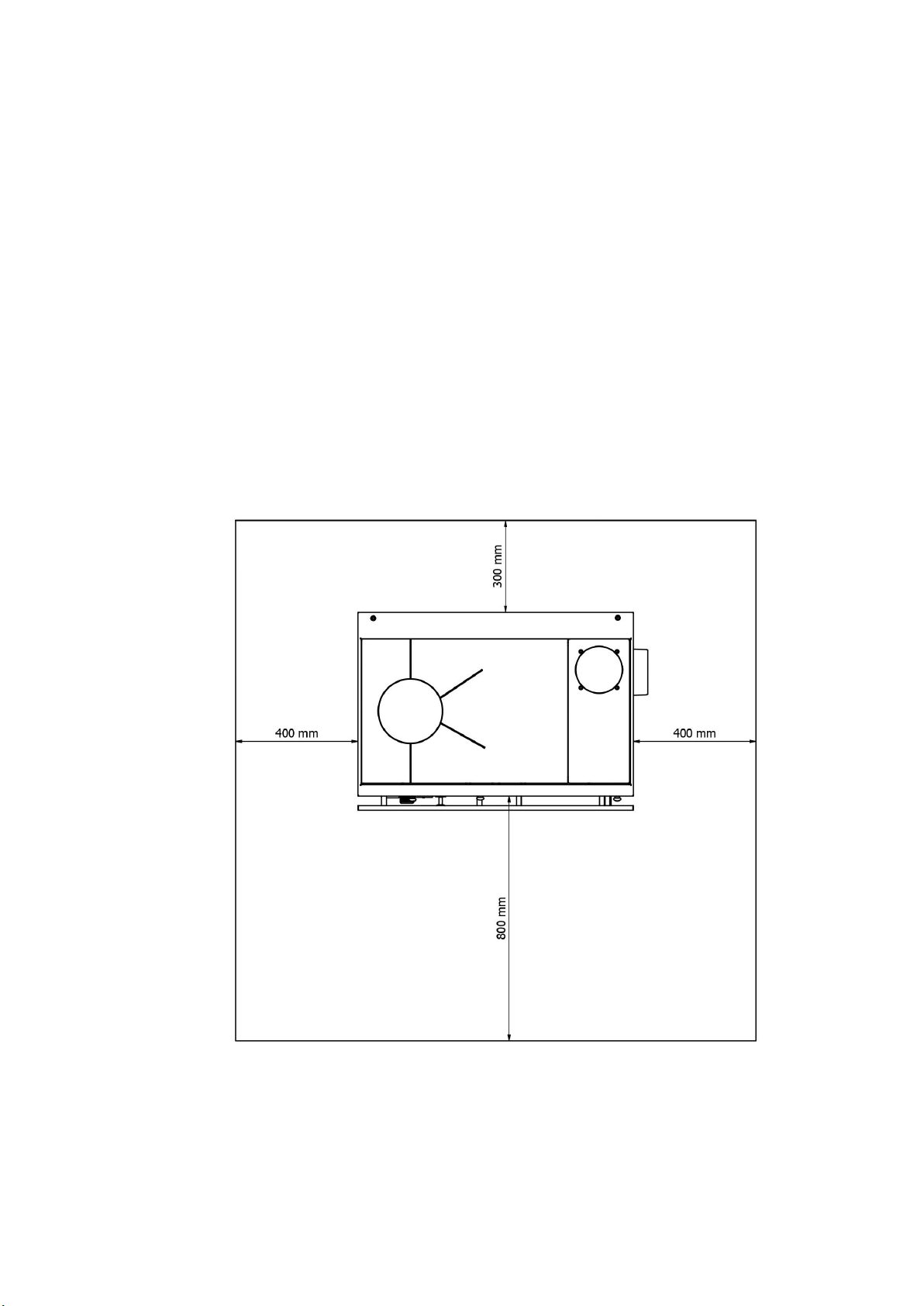
− Whether the room in which the solid fuel is being installed is appropriate, which is expressed as the minimum size of
the room required for the installation as prescribed by the solid fuel manufacturer,
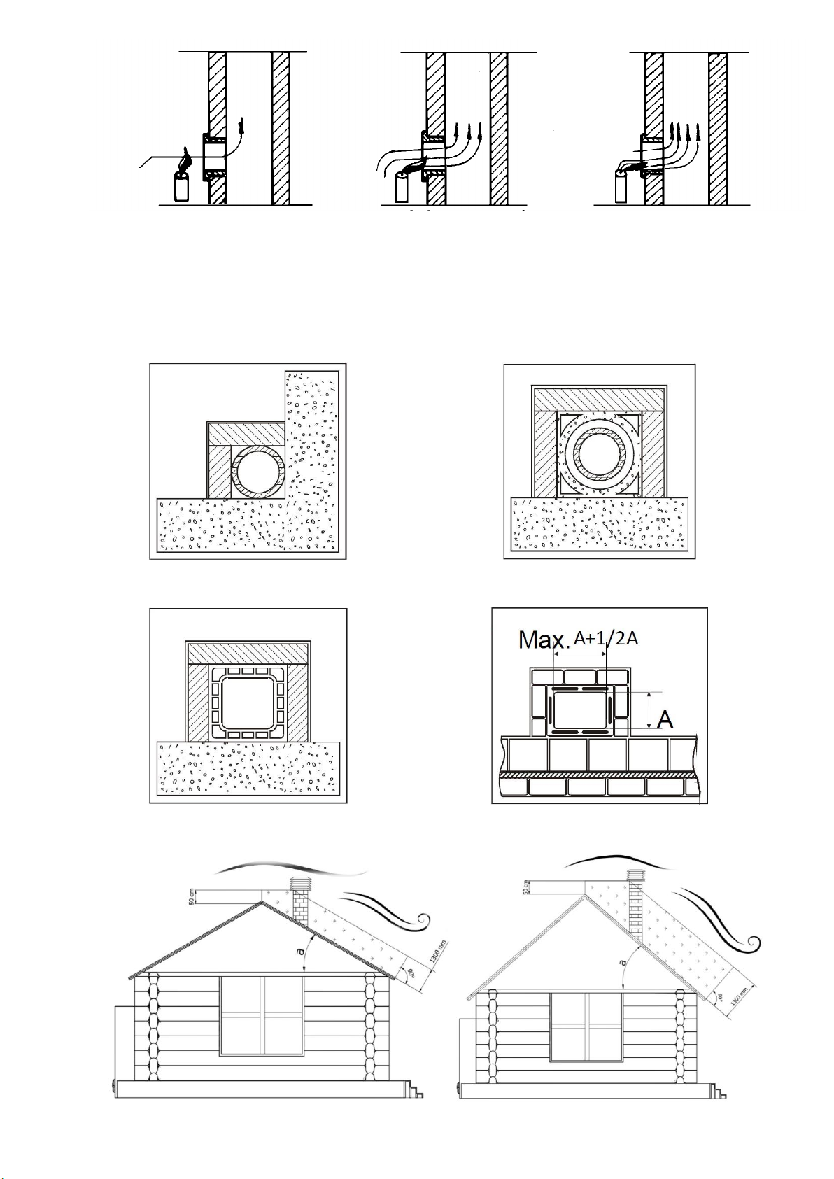
− Instructions of the heat generator manufacturer, related to the requirements of the smoke discharge system
(smoke discharge ducts and pipes),
− The internal cross section of the chimney, material the chimney is made of, cross-sectional uniformity, whether
there are any obstacles and barriers in the chimney,
− The height and vertical extension of the chimney,
− The height above the sea level at the place of installation/incorporation,
− The existence and suitability of a wind resistant protective cover of the chimney,
− The possibility of providing the external air intake and the size of required openings,
− The possibility of the simultaneous use of the solid fuel which is to be installed, together with the other equipment
already existing in that place.
If the results of all the checkups are positive, then the installer may proceed with the incorporation/installation of the solid
fuel. The instructions provided by the solid fuel manufacturer, as well as the fire prevention standards and safety standards
must also be observed.
When the installation is completed, the system must be put into a trial operation for at least 30 minutes in order to check
up all the packing and seals of the system.
When the incorporation and significant details are completed, the installer is obliged to provide the client with the
following:
− The Use and Maintenance Manual issued by the solid fuel manufacturer (if such a manual has not been delivered
with the solid fuel),
− The documents required for the compliance with existing standards.

2
3. APPEARANCE AND STRUCTURE OF A SOLID FUEL WITH A FLOOR
HEATING BOILER (fig.1)
Figure 1
1. Solid fuel cover
2. Cooking panel (hob)
3. Cooking panel extension
4. Butterfly knob for opening and closing
5. Oven door (oven)
6. Oven thermometer
7. Firebox door
8. Secondary air regulator knob
9. Ashtray door
10. Thermostat knob (combustion regulator)
11. Rod for shaking ash
12. Ashtray (ash box)
13. Ember holder
14. Draving for wood
15. Cover for cleaning
16. Manometer
17. Thermometer
18. Hob cover
19. Thermostat flap
20. Flue extension
21. Cover of opening for cleaning
22. Handrail
23. Grate carrier
24. Additional cover
25. Rod bracke

2
4. SAFETY AND RELIABILITY IN SOLID FUEL OPERATION
The solid fuel for floor heating is constructed so that it enables maximum safety during operation.
Safety during solid fuel operation is provided in three ways:
- combustion regulator (thermostat) (fig. 1 pos.10), located in the ashtray door, which automatically closes the air intake in
the solid fuel firebox when the set water temperature in the boiler is reached,
-Thermal valve (thermal fuse) (Fig. 7, Item 13 and Fig. 7a) when installed in the heating system serves as a thermal fuse if
the solid fuel becomes overheated,
- safety valve (Fig. 7 and 8, Item 5) which MUST be installed on an R1/2" connection (Fig. 4, Item 4.)
NOTE:
Thermal valve and safety valve are not delivered with solid fuel, while the thermostat is installed on the solid fuel's ash pan
door.
5. SOLID FUEL PLACEMENT (INSTALLING)
- The solid fuel may be installed in the kitchen part or at some other convenient spot.
- An inflammable pad should be put under the solid fuel.
- If the pad is flammable (wood, plastic), place a tin plate that should protrude from the lateral sides with 10cm and 50cm
from the front side.
- The furniture and objects located in front of or close to the solid fuel must not be from flammable material.
If they are from flammable material, then the minimal distance from the solid fuel (Figure a).
- If a cupboard is installed above the solid fuel, the minimum distance between the solid fuel hob and the cupboard should
be at least 70cm.
- Flammable materials (for example wallpapers, frames, doors etc.) from the flue should be at a distance of at least 20cm.
This distance may be reduced if thermal insulation is placed on the flue pipe and the temperature of the surrounding objects
does not exceed 80°C.
- The solid fuel should be installed in horizontal position or slightly elevated from the back side (3-4mm).
Figure a
All minimum safety distances are indicated on the product data plate, DO NOT use lower values than specified (see
INFORMATION ON CE MARKING).
5.1. INSTRUCTIONS FOR COMBUSTION AND VENTILATION
Combustion air must be supplied to the rooms where the range is installed. The room must be constantly ventilated.
An fresh air opening must be located in the lower part of the room and air should enter through it.
A) Supply of combustion air by means of a pipeline through the basement. This connection option leads to a preheating of
the combustion air, which is useful for a good and clean combustion. The installation of pipelines in the basement is simple.
B) Supply of combustion air through the basement. The combustion air is preheated. The basement space must be
separated from the ventilation system of the house and open to the outside. High levels of dust and moisture should be
avoided.

3
C) Supply of combustion air from above. Air supply from above can only be performed with tested chimney systems.
In this case, it is necessary to calculate the dimensions of the chimney!
D) Supply of combustion air directly from outside. If combustion air is directly supplied through the outer wall, it shall be
only be slightly preheated, which is unfavorable for a clean combustion. In this case there is also risk of condensation!
NOTE: We do not recommend these versions of air supply! However, if you use these options, consult a qualified
professional.
In the room where the heating device is installed, it is necessary to ensure sufficient supply of fresh air. If the windows and
doors are hermetically sealed or if there are air-extracting devices, such as hoods, hair dryers, fans etc., in the room where the
range is installed, combustion air (fresh air) must be supplied from outside. In any case, this should be discussed with a
competent chimney sweep before installing the range.
Supply of fresh air in the room where the range is installed
6. FLUE INSTALLING
Review the unpacked solid fuel and become familiar with the parts of the solid fuel and the accessories, and especially pay
attention to the following:
- The special channels of the firebox door, the ashtray, the cover for cleaning and the hob frame should have pigtails with
no asbestos that seal well and do not allow uncontrolled air intake.
- The combustion regulator (thermostat) with regulation knob (fig.1 pos.10) should properly open and close the regulator
flap (fig.1 pos.19).
- The ember holder (fig.1 pos.13) should be properly placed in its bearing and should be easily open.
The flue connection (plug), that is delivered together with the solid fuel and is placed in the drawer for wood, should be set
and screwed on the openings of the plug carrier (hob) or on the opening on the lateral side. The existing cap must be
previously removed and the same screws for connecting plugs should be used.
WARNING:
If Your flue is not the best or it is with suspicious quality, we recommend that You install a flue connection on the plug
carrier (from the top), and not on the side.
The flue reaches its rated power if the flue draft is 15,5 Pa. We recommend the following flue sizes with which this draft is
obtained:
Solid fuel
Denotement
Rated heating power
(kW)
Flue height (m)
6
7
8
9
10
ALFA TERM 20
wood
Dimensions of light surface (mm.)
22,9
145x200
145x145
145x145
145x145
145x145
- Proper flue and meeting other requirements set out in the material that follows are a prerequisite for flawless functioning
of the solid fuel.
- The flue connection should be installed with uplifting.
- Horizontal flue pipe pieces longer then 0,5m should have an uplifting of 10towards the flue.
- The flue extension, flue pipes and the flue must not be narrowed.
- All connections as well as the flue must be well sealed, with no soot and grime in flue pipes.
- The flue should be protected from cold (it should be heat insulated). This especially applies for flues made of sheet metal
and flues built on external walls.
- Flue pipes that do not have thermal insulation and do not stand vertically, must not be longer then 1,25m. Check of the
draft strength is performed by using candles (fig. 2).

4
slight draft good draft very strong draft
Figure 2
The flue is functioning well if it satisfies the following conditions (fig. 3):
- It protrudes above the roof top (ridge) at least 0,5m.
- It is higher than the neighboring house that is close to the flue, a tree or some other barrier.
- It is in the internal walls of the house or it is well insulated if it is in the external walls.
- The extension should be closely connected to the flue if it is being extended.
- The flue pipe should not be inserted deeply in the flue opening as this reduces the space for smoke output.
- All other unnecessary openings as well as the door for cleaning should be well closed (sealed) so that so called “false” air
would not be created.
AISI 316 steel chimney with double insulated chamber,
made of material resistant to 400°C. Optimal efficiency
100%
Fireproof chimney with double insulated chamber and an
outer lining of lightweight concrete.
Optimal efficiency 100%
Traditional clay chimney with recesses. Optimal efficiency
80%
It is forbidden to use chimney pipes that have a rectangular
internal cross-section with
a ratio that differs from the plan. Modest efficiency 40%

5
Chimney - positioning and distance
7. INSTALLING SOLID FUEL IN WATER HEATING SYSTEM
Installing of the solid fuel should be performed by a qualified person according to the appropriate project.
The solid fuel is intended for floor and central heating.
It can be installed in closed and open heating system. Adhere to the regulations JUS M.E7.201 and JUS M.E7.202.
Diagrams of closed and open system are shown on fig.7 and fig.8.
The back of the boiler and connections are shown in Fig. 4 where:
Figure 3
- Item 1 is an R1" connection with an outer thread for the flow pipe,
- Item 2 is an R 1" connection with an outer thread for the return pipe,
- Item 3 is an R1/2" connection with an inner thread for installation of the thermal valve safety pipe,
- Item 4 is an R1/2" connection with an inner thread for safety valve installation.
7.1. DISCHARGE AND RETURN LINE (fig.4 pos.1 and 2 and fig.7 and fig.8
pos.3 and 10)
The outlets of the discharge and return water of the boiler are 1" and they must not be reduced, that is, narrowed up to the
first bifurcations. Use steel pipe 1" or copper pipe with external diameter F28mm. (or bigger diameter).
When performing the installation, strictly pay attention to the pipe slopes which should be 0,5% (5mm. per meter of pipe)
and to the system venting (boiler, pipes, radiators).
On the discharge line you may set thermal-manometer although thermometer and manometer are mounted on the front
side.
Set a “by-pass” on the return line with a pump, expansion vessel and valve for filling and draining the system. When
mounting the pump, pay attention to the pump direction.
Warning:
Make a "by-pass" only if there are conditions for so called gravitational heating.
7.2. THERMAL VALVE WITH BUILT-IN THERMAL PROTECTION AND
ADDITIONAL ELEMENTS FOR CONNECTION
To install thermal valve it is necessary to purchase and install:
1. Thermal valve with built-in thermal protection type 544, 1/2", product Caleffi (Fig. 7a) and Fig. 7, Item 13.
2. Slope pressure regulator with manometer 1/2", the same or similar as shown in Fig. 7b and Fig. 7, Item 19.
3. Filter for cold water at the input of the water supply to the thermal valve, Fig. 7, Item 20
4. Filter for hot - boiling water intake of the boiler and water outlet of thermal valve, Fig. 7, Item 21.
Note:
These components are not included with product for central heating you bought!
Installation of thermal valve with built-in thermal protection (Fig. 7, Item 13 and Fig. 7a) with additional elements ensuring
safe operation, such as pressure regulator (Fig. 7, Item 19 and Fig. 7b). Water filter on the boiler intake (Fig. 7, item 20) and
water filter on the boiler outlet in closed central heating system is MANDATORY. This specially refers to a closed system,

6
when the radiators are submerged and where in case of termination of the pump operation for any reason, the water
temperature in the boiler rapidly increases and overheating occurs very quickly.
In the open central heating system, installation of thermal fuse is not mandatory.
7.2. 1 . THER MAL V ALV E WITH B UILT - I N THER MAL PR OTE CTIO N (Fig. 7 , I t em 13 and Fig. 7 a)
Thermal fuse is installed near the solid fuel, depending on the available space. It can be installed in any position. You
should take into account the direction of cold water intake and hot water outlet from the boiler which is clearly marked on the
valve body.
The thermal fuse probe (Fig. 7, Item 22) is best to place in the thermal valve connection (Fig. 7, Item 18). It can be placed
on the discharge - distribution pipe (Fig. 7, Item 3) but at a distance from the boiler of 500 mm the most or at the highest point
of the boiler before the exhaust pipes.
Seal it with hemp or other sealing material by tightening.
Fig. 7 shows the thermal valve installation diagram.
The device is of one piece with the thermal valve and valve for filling.
Valve opening temperature is 100°C (+0°C/-5°C).
The fluid recommended in the installation is water and glucose antifreeze of 30%.
Note:
At reaction, and valve operation, during fluid cooling in an overheated boiler part of the new fluid is injected into the boiler,
but the part is also ejected from the boiler. It will be poured down the drain. If the antifreeze is in the installation you must
keep in mind that a certain percentage will go out and pour down the drain!
We recommend the thermal valve Caleffi type 544, 1/2" as shown in Figure 7a.
7.2. 2 . SLOP E PRE SSURE R EGU LATO R 1/2" WITH MA NOME TER (F ig. 7, Item 19 and F i g. 7b)
When installing the thermal valve it is required to mount the slope pressure regulator as shown in Fig. 7, Item 19. The
pressure that is maintained by pressure regulator must be set at a higher pressure than the pressure that is in the heating
system. If you do not have a higher water pressure of at least 0.8 bar compared to the pressure in the heating system thermal
valve will not work or cannot inject cold water into the boiler that needs to be cooled.
Pressure regulator should be set to 2.8 to 3 bars.
You should take into account the direction of placing the slope pressure regulator
7.2. 3 . WATE R FILT ER O F THE BO ILE R I NTAK E (Fig. 7 , It em 20)
In front of the slope pressure regulator on water intake from water supply line it is necessary to install a filter that will clean
the water from solid objects, primarily of sand, which can damage the tap seal or seals of the thermal valve and the slope
pressure regulator.
This filter does not need to be resistant to high water temperatures due to cold water that flows through.
7.2. 4 . WATE R FILT ER OF TH E BOI L ER O U TLE T (Fig. 7, Ite m 2 1)
It is required to install the filter on the boiler outlet which will clean the hot - boiling water from dirt and solid objects that
can damage the tap seals, or seals of the thermal valve.
This filter must be resistant to water temperatures up to 150°C.
NOTES:
- After the completion of thermal valve activation, checking the pressure in the installation and filling the system with cold
water is mandatory.
- In cases where antifreeze is used, after filling the installation with water it is required to check percentage content of
antifreeze in a mixture of water and antifreeze!
- To avoid elimination of the antifreeze agent solution from the installation, it is best to have backup battery supply of the
pump with an inverter.
7.3. SAFETY VALVE (fig. 7 and 8 pos. 5 and fig. 4 pos. 6 )
On the back side of the boiler under the hob, a connection R1/2" is welded (fig.4 pos.6) in which you are OBLIGED to set a
safety valve. The safety valve should be between 2,5 to 3 bar. It can be installed directly on the terminal or at a distance from
the solid fuel of 1m the most, provided that there is no block valve between the boiler and the safety valve.
In an open heating system, the safety valve is not put normally, but we advise that you put it as one more type of insurance
of the boiler and the system (due to unforeseen circumstances).
WARNING:
If the safety valve is not set as previously explained, the guarantee ceases.
7.4. THERMOMETER AND MANOMETER (fig. 1 pos. 16 and 17 and fig. 5)
On the solid fuel itself, on the additional cover (fig.1 pos.24) between the firebox door and the ashtray door, thermometer
and manometer are mounted (fig.1 pos.16 and pos.17, and fig.5) so they do not have to be placed on the installation.
The thermometer pos. 17 shows the temperature of water in the boiler (operating temperature) in °C.
The manometer pos. 16 shows the water pressure in the boiler, that is, in the system, in bars.

7
Figure 5 Figure 6
8. PRACTICAL INSTRUCTIONS AND ADVICE FOR HEATING SYSTEM
USE
- We recommend that you choose a closed system due to the risk of corrosion in an open heating system.
- All connections must be well sealed and fastened.
- Before commissioning, the complete installation should be examined with water with pressure of 2,4 bar.
- It is desirable that water is drained out from the system at least once because of the grime located in the system.
- For an installation in which only a solid fuel “alfa term 20” is connected, we recommend expansion vessel from 18 (l) but
not less than 12(l) which would be placed on returning water, as close as possible to the boiler, and no block valve should be
set between the boiler and the expansion vessel.
In order to reduce the risk of condensation, it is recommended to use a three-way mixing valve with a fitting thermostat
when installing the solid fuel.
We recommend that you do not adjust the water temperature below 57 ºC due to possible condensation of the boiler,
neither above 75ºC.
Scheme of the hydraulic installation of a solid fuel (radiator heating)
Legend:
1. Solid fuel
2. Auto Air Vent
3. Safety valve 3 bar
4. Non-return valve
5. Circulation pump
6. Closed expansion vessel
7. Contact thermostat
Note:
- It is mandatory to install a thermal discharge valve with thermal
protection, the so-called thermal fuse in accordance with the
recommendations from the technical instructions.
- Install the safety valve directly on the boiler, at the connection
provided, which is described in the instructions.

8
Scheme of the hydraulic installation of a solid fuel (radiator and floor heating)
Figure 7a Figure 7b
- It is desirable to insert a pump R1" for more speed whose flow capacity is always appropriate for the current need of the
system. Directly in front and behind the pump, install shut-off valves so that displacement of the pump could be performed for
repairs, changes etc., without releasing water.
- Mount a tap for the filling and draining the system at the lowest system point.
- Before commissioning the system should be filled with water as follows:
a) If the system is open, fill the system through the tap for filling and draining until water starts to leak from the overflow
pipe of the expansion vessel,
b) If the system is closed, the system pressure (working pressure) should be 11,5 bar.
In both cases, fill the system slowly so that air can come out through the air releasing valves. If the valves do not open
themselves, they should be manually open until water starts to leak, than close them.
- The water from the heating system should not be drained in summer neither since it protects the internal side of the system
from spreading oxidation (corrosion).
- If you don’t use the boiler for a longer period in winter, and there is not antifreeze asset in the system, it is best to drain the
water from the system. At the same time open the valves on the radiators, the combined valves and the other shut-off
elements in the system.
- Fire must not be kindled if the water in the boiler is frozen, neither if there is not enough water in the boiler.
9. COMMISSIONING AND STOKING
Before stoking, the entire system for floor (central) heating should be filled with water, well vented and the solid fuel should
be properly connected to the flue as explained in the previous paragraphs.
Legend:
1. Solid fuel
2. Auto Air Vent
3. Safety valve 3 bar
4. Hydraulic crossover
5. Circulation pump
6. Non-return valve
7. Circulation pump
8. Closed expansion vessel
9. Three-way mixing valve with fitting thermostat
10. Circulation pump
11. Underfloor heating separator
12. Contact thermostat
Note: - It is mandatory to install a thermal discharge valve with thermal
protection, the so-called. thermal fuse in accordance with the
recommendations from the technical instructions.
- If only underfloor heating is connected to the stove, be sure to install
a storage tank (BUFFER)
- Install the safety valve directly on the boiler, at the connection
provided, which is described in the instructions.

9
WARNING:
The solid fuel must not be used without water. It must be connected to an installation on which consumers (radiators) are
connected with a minimum power of 8 kW.
When the system is cold, the flap of the power regulator (combustion regulator, thermostat) located in the ashtray door
(fig.1 pos.10 and pos.19) should be open. Pull ahead the butterfly knob for opening and closing (fig. 1 pos.4 and fig. 16). That
way the butterfly knob is open and kindling is enabled. Later when the solid fuel is inflamed, we adjust the regulator flap on the
appropriate position that depends on the pulling power of the flue and the desired power, and the butterfly knob should be
pushed back. Then the butterfly knob is closed and full use of the combustion is enabled, thus better heating, cooking and
baking. During this, the door of the firebox and the ashtray (fig. 1 pos. 7 and pos. 9) must be closed if we want regulated
combustion. The butterfly knob for kindling is open only during the kindling of the solid fuel (10 to 15 minutes).
The firebox and ashtray doors can be open and closed manually, as well as with the bent wrench as shown on figure 6.
We stoke the solid fuel as all permanently burning solid fuels on solid fuels. When the grade is in lower position, we
perform kindling through the open door of the ashtray and the ember holder (fig.9 and fig.10). We open the ember holder (fig.1
pos.13 and fig.9) by raising and pulling. When the grate is in upper position through the open door of the firebox (fig.11) on the
grate we put paper, small pieces of chopped wood and kindle. When everything is burning well, we can fill the solid fuel with
wood if the grate is in upper position. If the grate is in lower position, do not put at once all the needed heating material for full
firebox, but divide it on two or three parts and put it in the firebox at intervals of 10-15 minutes on flaming heating material.
The solid fuel filled in this manner burns from 1 to 6 hours, depending on the intensity of combustion in the solid fuel and the
adjusted power regulator (thermostat).
Figure 9 Figure10 Figure 11
The firebox can be filled from the upper side as well (fig.12). The cover is lifted by using a wrench and firewood is put. It is
not recommended to put some organic waste in the solid fuel (plastic bags, bones etc.) because in this case tar collects on
the walls of the flue channel and this can cause a fire.
After every filling it is recommended that the solid fuel burns with maximum power for at least half an hour since in the
beginning all volatile compounds in the fuel burn, which are actually the main causes for condensate creation in the solid fuel.
Figure 12
10. GRATE USE IN UPPER AND LOWER POSITION
For cooking, baking and frying in the transit period, the upper grate position is used (fig.11) so that the flame could directly
reach the hob thus saving the costs for cooking, baking and heating.
The solid fuel is delivered with a grate in lower position. In order to move the grate from the lower to the upper position, it
is necessary to do the following:
- Remove the hob from the solid fuel and open the door of the firebox and the ashtray.
- The grate should be pushed completely back with a rod for shaking the grate and then through an opening of the ashtray
door and the space for ash and the front part of the grate should be lifted by hand and should be pulled out from its bearing
(position). After this, the carrier of the grate is lifted and pulled out.
- The placement of the grate in upper position is performed in reverse order. The grate carrier is placed on the grate
holders (pieces 4) welded in the boiler firebox in front and on the back side (pieces 2+2) (fig.1 pos.23). In the grate carrier

10
bearing insert the grate under an angle (aslant) so that the back part of the grate enters first and then put down the front part
of the grate. Move the grate forward and backward so that it lies well in the grate carrier bearing. Put the hob in the carrier
bearing of the hob frame.
- Placement of the grate in lower position (fig.9 and 10) is performed in the same manner as the upper position, provided
that in the end the front part of the grate is lifted a little and through the rectangular opening of the rod carrier (fig.1 post.25)
the rod for shaking the grate should be inserted. The grate is slowly put down so that the grate notch falls in the opening of
the rod for shaking the grate.
Warning:
- In the lower grate position, the heating of water is better, larger number of radiators can be heated and bigger surface of
living space, but cooking is more difficult.
- In the upper grate position, the heating of water is weaker, small number of radiators can be heated and small surface of
living space, but cooking is much easier.
- In both grate positions baking is the same (it is not impeded).
11. AUTOMATIC REGULATION
The solid fuel power is adjusted with a thermostat (power regulator, combustion regulator) located in the ashtray door and
which automatically adjusts the lapse of the regulator flap depending on the adjustment of the regulating knob (fig.1 pos.10
and pos.19) and the height of water temperature in the solid fuel heater. The regulation knob has many positions written on
the knob and this is shown in table 1 as follows:
Table 1
Position of regulator knob
0
3
4
5
7
9
Water temperature in the solid fuel (C)
Closed regulator
30
40
50
70
90
The cover (flap) for air in the power regulator system completely regulates the air intake for combustion it he remaining
openings are closed.
12. SECUNDARY AIR REGULATOR
A secondary air regulator is placed in the firebox door (fig.1 pos.8 and fig.13). It is used for regulating the subsequent
ignition and combustion of unburned gases. Its opening and closing is performed manually through a knob positioned on the
firebox door.
Leave the secondary air regulator open when the grate is in lower position while solid fuel usage. Close the secondary air
regulator when the grate is in upper position.
13. COOKING, BAKING AND FRYING
The solid fuel is mainly used for heating during the heating season. For this purpose the grate is placed in lower position.
For quicker baking, cooking and frying use dry wood for stoking.
The butterfly knob for stoking must be closed, and the power regulator must be open. After baking, cooking and frying is
completed, put the power regulator on the green position.
When baking, the water temperature should be increased to at least 60C, if necessary by closing some radiators while
baking, and adjust the solid fuel temperature according to the food that is baked.
14. HEATING MATERIAL
The heating material can be kept in the heating material drawer (fig.14). The drawer moves on rails. If we want to take out
the drawer from the solid fuel we must lift it up so that it would fall out from the rails.
Use heating material that is shown in the table 2 which will ensure that the boiler has rated thermal power of a flue draft of
15,5 mbar (15,5 Pa).
Do not burn dust, sawdust and waste that releases smoke intensively!
Figure 13 Figure 14 Figure 15
Table 2
Heating material
Heating power (kJ/kg.)
Dry beech firewood
15300
WARNING:

11
In order to get rated heating power and as higher rate of usage, we recommend that you use dry beech wood cut with a
length of L=33cm as a heating material.
15. CLEANING AND MAINTENACE
Before every filling with fuel, the solid fuel grate must be cleaned with a spade by opening the ember holders or through
the open door of the firebox. The ash from the ashtray should be removed at least once a day and larger residues (slag)
should be removed by opening the door of the ashtray and the ember holder. The clean heating surfaces guarantee economic
operation of the solid fuel. Cleaning of the solid fuel once a month is recommended, and if necessary more frequently as well.
Do not clean enameled surfaces of the solid fuel and the solid fuel frame with a wire brush and wire sponge since the
enamel and the protection may be damaged, instead, use a damp cloth and cleaning assets and fine detergents. Clean the
oven after every use while it is still warm. Leave the oven door open after cleaning for couple of minutes so that unpleasant
odor would not be sensed during the next warming up.
Temporarily clean the solid fuel hob with fine sandpaper and in case of longer brakes it should be greased with oil that
does not contain acids (vegetable oil). Remove burnt things from the hob by using a palette knife or a knife and eventually
treat it with graphite or ash from the ash box or with oil.
It is forbidden to artificially cool the solid fuel with unnatural draft and soaking the firebox with water so that it gets cold.
16. SOLID FUEL STORAGE
After finishing the stoking season, the solid fuel should be cleaned from ash and smoke. Water should be released only in
case when some repair of the installation should be performed. If the installation is not used in the heating season, pour a
certain quantity of some antifreeze liquid or release the water from the installation as a protection from freezing.
17. FAULTS
Table 3
RB
Faults
Possible cause
Elimination
1
Water pressure in
installation is slowly
decreasing
The installation
does not seal
Check the sealing of welded connections, threaded fasteners, nuts etc.
2
Cold radiators on the
highest installation
point and a sound is
heard
Air in the
installation and
low pressure in
the installation
Increase pressure in the installation and release air from the installation
and from radiators
3
Moisture builds up in
the boiler
1. Condensation
of flue gases
1. Compare the total power of the installed radiators with the power of the
stove. If the total power of the installed radiators is greater than the total
power of the stove delivered to the water, replace the furnace with a
stronger one, or adjust the number of radiators to the power of the stove.
4
The radiators do not
heat along the entire
length
Air in radiators
Release air from radiators through the vent valve
5
The safety valve drains
water from the
installation, and the
pressure is less than 3
(2,5) bar
The pressure in the
installation is more
than 3 (2,5) bar and
the safety valve does
not drain water from
the installation
Safety valve
failure
Replace safety valve
Safety valve
failure
Replace safety valve
6
Sudden water
temperate increase in
the installation
Air in the
installation
Perform radiator venting
Closed valves
towards radiators
Open all valves in the heating system and provide normal water
circulation in the installation
Circulation pump
failure
The circulation pump should be repaired or replace it thereby allowing
operation of the heating system
Electrical power
loss
You should open all valves that reduced the heating system. This mostly
refers to the “by-pass” valve.
Stop or reduce stoking with strong control so that the water temperature
in the system would not exceed 90C until electricity arrives.

12
7
Sudden pressure
increase in the
installation while
water temperature
increase
Decreased
pressure in the
expansion vessel
or completely
empty. Remove
the cover or the
vessel valve cap
and release some
air through the
valve. If the
membrane is
destroyed, water
shall leak from
the valve, and if it
is only half-
empty, only air
will come out
If water is leaking from the valve, replace the expansion vessel.
If only air comes out from the valve, remove the installation vessel and
pump it. The pressure in the vessel must be equal to or greater than
height difference of the highest and lowest installation point. Example:
For height difference of 5m. the pressure is Pmin.0,5 bar.
Air in the
installation
Perform venting of the installation
8
The circulation pump
does not switch on or
blow a fuse
No power on the
electrical
connection.
Loose
connectors.
Check and tighten the screws at the connection spots. Check and if
necessary, replace the fuses, eliminate the malfunction of the motor or
installation connection
Capacitor failure
Replace the capacitor
Rotor blockage
Before the start of each heating, examine the easy rotor turning. Hot water
deposition may lead to rotor blockage. Turn around the motor shaft with a
wrench until free turning of the rotor is enabled.
The pump is
blocked due to
sediment
Disassemble and clean the pump.
9
The thermometer or
manometer does not
show the amount of
temperature or water
pressure in the
installation
Thermometer or
manometer failure
Replace the thermometer or manometer
10
Noise (sounds) from
the eating system
Defective pump.
Great clearance
between the rotor
shaft and
bushings
Reduce pump speed. Replace the pump envelopes or the entire pump
The pump is
functioning at too
high speed
Select low speed.
Air in installation
Release air from the heating system
Loose knobs or
some screw on
the solid fuel
Tighten knobs and screws
11
Sounds in the pump
The pressure at
the pump suction
part is to low
Increase system pressure or check the expansion vessel.
12
The solid fuel
overheats, loud noise
(cracking) is heard in
the boiler of the solid
fuel.
Electricity outage
has occurred, the
circulation pump
does not work
and the boiler of
the solid fuel
overheats. There
is a danger of
boiler rupture.
To avoid this occurrence, it is best to have backup battery power supply
of the circulation pump with an inverter.
Installation of a thermal exhaust valve (Fig. 7, pos. 13) is required as
additional security against solid fuel overheating.
If you do not have backup supply of the circulation pump or a thermal
exhaust valve installed, then you should open the bypass valve connected
in parallel with the circulation pump on the pipeline system and remove
embers from the solid fuel.
13
Cooling thermal fuse
is activated (thermo
valve) because
water temperature
increased over 95C
due to:
- loss of
electricity
This is proper and do not touch anything. When the system is cold,
thermal valve will be closed.
After that, check the pressure in the installation and fill the system to the
required.
- open ashtray
door and no
regulated
combustion
Close the ashtray door and through the knob on the cover of the ashtray
door and thermostat, reduce the water temperature in the system.

13
- the grate is in
lower position
and small number
of radiators are
switched on
Transfer the grate to upper position or switch on some other radiator.
Keep the ashtray door closed.
14
Water condensate in
the boiler
Damp heating
material
Change heating material
Too low
temperature of
returning water
from the heating
system
Insert combined valve or switch off some radiator from the heating
system
15
Outlet water
temperature is not
appropriate (low)
Non-calorific
heating material
Change heating material
Heating system is
oversized
(a large number of
radiators)
Switch of some radiators
Little heating
material is
inserted in the
firebox
Increase the quantity of heating material in the firebox
16
Fire does not burn
regularly
Weak flue draft
Make a new flue or repair the old one
Flue pipe
connections do
not seal.
The doors on the
solid fuel and the
flue do not seal.
The flue draws
“false air”.
Seal all connecting spots so that “false air” would not occur
17
There is not enough
heat in baking,
cooking
The thermostat is
set to a lower
temperature
Increase water temperature through a thermostat or shortly open the
ashtray door
18
There is too much heat
in baking, cooking
The thermostat is
set to a high
temperature
Reduce water temperature through the thermostat or stoke moderately
19
The boiler-solid fuel
releases smoke during
initial startup
Combustion and
heating of the
solid fuel and flue
It is normal for the solid fuel to release some smoke during initial startup,
and this stops after some time.
20
The boiler-solid fuel
releases smoke during
regular use
Uncleaned flue,
flue pipes and
solid fuel
Clean the internal part of the flue, the flue pipe and solid fuel.
Damp heating
materials of the
heating materials
you use
intensively
release smoke
Change heating material. Use dry hating material and heating material
that does not release smoke
Overloaded
firebox
Fill the firebox slowly, gradually, in a couple of times
Bad flue
Repair or make a new flue
21
The grate is stuck
when cleaning is
performed
Some spike is
stuck, slag or
something else
on the grate
Clean the grate of undesirable objects

14
18. Overall dimensions of solid fuel ALFA TERM 20
19. DETERMINING THE REQUIRED HEAT OUTPUT
There is no absolute rule that would allow the calculation of the required heat output. This power is determined by the
space you want to heat, but it also largely depends on the insulation. On average, the required heat output for a properly
insulated room would be 30 kcal h per m3(at an outdoor temperature of 0°C).
Indicative combustion value
Required quantity in the ratio of 1 kg of dry wood
Fuel
Unit
kcal/h
kW
Dry wood (15% moisture)
kg
3600
4.2
1.00
Wet wood
(50% moisture)
kg
1850
2.2
1.95
20. TURNING THE APPLIANCE OFF
In the event of fire or overheating, close the air inlet covers and DO NOT open the fireplace door. Extinguish the fire with
appropriate means (home fire extinguisher...). NEVER USE WATER TO EXTINGUISH THE FIRE! Also notify local firefighters in
case of fire. Follow local fire protection regulations!
Table of contents
Other Alfa Plam Cooker manuals