Alfalaval Toftejorg MultiJet 40 User manual

MJ40_IM_SP
Covering:
Standard Machines
Machines delivered with ATEX Certification in accordance with Directive 2014/34/EU
TE91A170
First published: 2001
ESE02850-EN2 2018-10
Original manual
Instruction Manual
Alfa Laval Toftejorg™MultiJet 40


Table of contents
The information herein is correct at the time of issue but may be subject to change without prior notice
1. EC/EU Declaration of Conformity .................................................................. 5
2. Safety .................................................................................................... 6
2.1. Important information ............................................................................. 6
2.2. Warning signs ..................................................................................... 6
3. Introduction ............................................................................................ 7
3.1. Introduction ........................................................................................ 7
3.2. Intended Use ...................................................................................... 7
3.3. Patents and Trademarks ......................................................................... 7
3.4. ATEX Marking ..................................................................................... 8
3.5. Quality System .................................................................................... 8
4. Installation .............................................................................................. 9
4.1. General Description ............................................................................... 9
4.2. Functioning ........................................................................................ 9
4.3. General Safety and Installation Instructions .................................................... 10
4.4. Special Conditions for Safe Use in Accordance with ATEX Certification .................... 11
5. Operation ............................................................................................... 12
5.1. Normal Operation ................................................................................. 12
6. Maintenance ........................................................................................... 13
6.1. Service and Repair of ATEX Certified Machines ............................................... 13
6.2. Preventive Maintenance .......................................................................... 14
6.3. Top Assembly ..................................................................................... 16
6.4. Bottom Assembly ................................................................................. 18
6.5. Hub Subassembly ................................................................................ 20
6.6. Stem Subassembly ............................................................................... 22
6.7. Gear Subassembly ............................................................................... 24
6.8. Replacement of Collar Bushes .................................................................. 26
6.9. Replacement of Ball Races ...................................................................... 28
6.10.Replacement of Main Collars .................................................................... 30
7. Trouble Shooting Guide .............................................................................. 32
8. Technical data ......................................................................................... 33
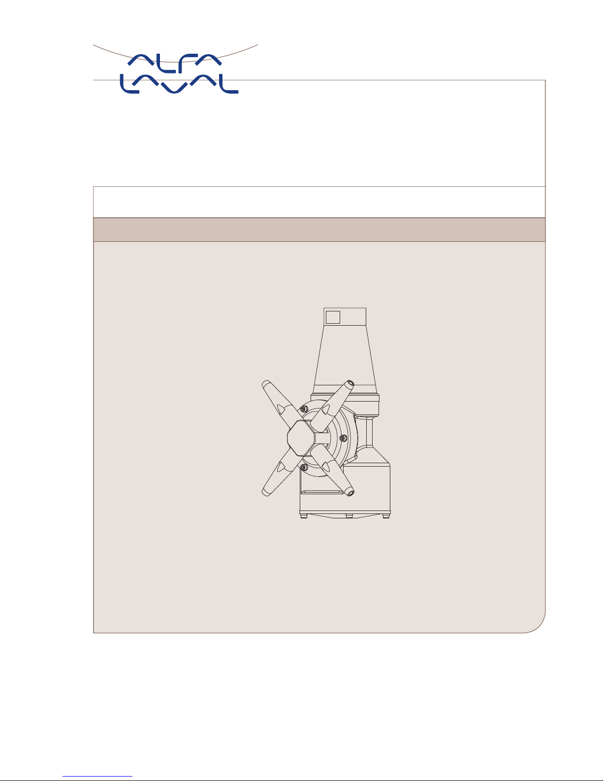
8.1. Alfa Laval MultiJet 40 Toftejorg with 2 nozzles ................................................. 33
8.2. Alfa Laval MultiJet 40 Toftejorg with 4 nozzles ................................................. 37
9. Product Programme .................................................................................. 41
9.1. Standard Configurations ......................................................................... 41
9.2. Available add-ons ................................................................................. 41
10. Parts Lists and Drawings, Service Kits and Tools ............................................... 42
10.1.Alfa Laval MultiJet 40 with 2 nozzles ............................................................ 42
10.2.Alfa Laval MultiJet 40 with 4 nozzles ............................................................ 44
10.3.Service kits and service intervals ................................................................ 46
10.4.Tools ............................................................................................... 47
11. General Information ................................................................................... 48
11.1.Service and Repair ............................................................................... 48
11.2.How to Order Spare Parts ....................................................................... 48
3

Table of contents
The information herein is correct at the time of issue but may be subject to change without prior notice
11.3.How to contact Alfa Laval Kolding A/S ......................................................... 48
4

1 EC/EU Declaration of Conformity
The Designated Company
Alfa Laval Kolding A/S
Company Name
Albuen 31, DK-6000 Kolding, Denmark
Address
+4579322200
Phone No.
hereby declare that
Tank Cleaning Machine
Designation
Alfa Laval Toftejorg MultiJet 40
Type
From serial number 2016-0001 to 2030-99999
is in conformity with the following directive with amendments:
Machinery Directive 2006/42/EC
DS/EN ISO 12100:2011
The Pressure Directive 97/23/EC
According to its own volume and the rated pressure range, the product is regarded an Article 3, paragraph 3 Equipment
Equipment Explosive Atmospheres (ATEX) Directive 2014/34/EU
(Applicable for machine certified as category 1 and 2 component, see machine engraving)
DS/EN 13463-1:2009, DS/EN 13463-5:2011, DS/EN ISO/IEC 80079-34:2011, Annex A, paragraph A.5.3 Rotating machines
EC Type Examination Certificate no. Baseefa10ATEX0188X
Marking: II 1 GD c T175ºCTamb0ºCto+140ºC
Baseefa Ltd., Certification body number 1180, Rockhead Business Park
Staden Lane, Buxton, Derbyshire SK17 9RZ, United Kingdom
The person authorised to compile the technical file is the signer of this document
Global Product Quality Manager
Pumps, Valves, Fittings and Tank Equipment Lars Kruse Andersen
Title Name Signature
Kolding 2018-10-01
Place Date
5

2 Safety
Unsafe practices and other important information are emphasized in this manual.
Warnings are emphasized by means of special signs.
Always read the manual before using the tank cleaning machine!
2.1 Important information
WARNING
Indicates that special procedures must be followed to avoid serious personal injury.
CAUTION
Indicates that special procedures must be followed to avoid damage to the tank cleaning machine
NOTE
Indicates important information to simplify or clarify procedures.
2.2 Warning signs
General warning:
6

3 Introduction
MJ40
3.1 Introduction
This manual has been prepared as a guide for installing, operating and maintaining your Alfa Laval Toftejorg tank cleaning
machine. Should you require further assistance, our Technical Sales Support department and worldwide net of sales offices will
be pleased to help you. Please quote the type, article and serial numbers with all of your enquiries; this helps us to help you.
The type and serial number are placed on the gear house of the tank cleaning machine.
Important
information:
Before installing the machine and setting it into operation, carefully read the General Safety and Installation
Instructions (page 10) and the special conditions for safe use in accordance with ATEX Certification Directive
2014/34/EU (page 11) and take all necessary precautions according to your application and local regulations.
NOTE
The illustrations and specifications contained in this manual were effective at the date of printing. However, as continuous
improvements are our policy, we reserve the right to alter or modify any unit specification on any product without prior notice or
any obligation.
The English version of the instruction manual is the original manual. We make reservations in regard to possible mistranslations in
language versions of the instruction manual. In case of doubt, the English version of the instruction manual applies.
3.2 Intended Use
The end-user should verify:
- that the tank cleaning machine is in conformity with respect to tank, vessel or container size in which it is used.
- that the construction materials (both metallic and non-metallic) are compatibility with product, flushing media, cleaning
media, temperatures and pressure under the intended use.
3.3 Patents and Trademarks
This Instruction Manual is published by Alfa Laval without any warranty. Improvements and changes to this Instruction Manual
may at any time be made by Alfa Laval without prior notice. Such changes will, however, be incorporated in new editions
of this Instruction Manual.
Alfa Laval Kolding A/S. All rights reserved.
The Alfa Laval logotype is a trademark or a registered trademark of Alfa Laval Corporate AB. "Toftejorg" is a trademark
or registered trademark of Alfa Laval. Other products or company names mentioned herein may be the trademarks of their
respective owners. Any rights not expressly granted herein are reserved.
7

3 Introduction
MJ40
3.4 ATEX Marking
If ordered with ATEX certificate:
ATEX Marking
The Alfa Laval Toftejorg MultiJet 40 is certified as category I components. The certification is carried out by the notified body
Baseefa, who has issued the certificate number 10ATEX0188X. The marking on the ATEX certified Alfa Laval Toftejorg MultiJet 40
is as follows:
Serial number explanation
Machines supplied with or without standard documentation:
yyyy-xxxxx: serial number
yyyy: year
xxxxx: 5 digit sequential number
Changes to the machine are not allowed without approval by the person responsible for the ATEX certification at Alfa Laval. If
changes are made – or spare parts other than Alfa Laval original spare parts are used - the EC Type Examination certification (the
ATEX Directive) is no longer valid.
Important ATEX
information:
Also see page 13 regarding special conditions for repair of ATEX certified machines.
3.5 Quality System
The Alfa Laval Toftejorg tank cleaning machines are produced according to Alfa Laval Kolding´s ISO 9001 international
Standard certified quality system.
8

4 Installation
MJ40
4.1 General Description
TheAlfaLavalToftejorgMultiJet40isamediadrivenandmedialubricated tank cleaning machine. As it is self- lubricating, there
are no lubricating substances such as oil grease etc. in the machine which need to be regularly changed.
4.2 Functioning
The flow of the cleaning fluid passes through a guide and a turbine, which accordingly is set into rotation. The turbine
rotation is through a gearbox transformed into a combined horizontal rotation of the machine body and a vertical rotation of
the nozzles.
The combined motion of the machine body and the nozzles ensures a fully indexed tank cleaning coverage. After 5 5/8
revolutions of the Hub with nozzles (5 3/8 revolutions of the machine body) one coarse cleaning pattern is laid out on the
tank surface. During the following rounds, this pattern is repeated 7 times, each of which is displaced 1/8 of the mesh in
the pattern. After a total of 45 revolutions of Hub with nozzles (43 revolutions of the machine body), a complete cleaning
pattern has been laid out, and the first pattern is repeated.
First cycle Full pattern
The speed of rotation of the turbine depends on the flow rate through the machine. The higher the flow rate the higher the
speed of rotation will be. In order to control the RPM of the machineforawiderangeofflowrates,theefficiencyofthe
turbine can be changed (100% and 0% Turbine/Inlet guide).
Apart from the jet flow through the nozzles, fluid is leaking through the top of the machine, at the hub and through the bottom
cover. The leakage between the moving parts at the top and at the hub are cleaning the gabs and thus preventing build-up
of material that might cause the friction. The flow through the bottom cover is due to the fact that the machine is media
lubricated and that accordingly a flow through the gearbox is needed.
9

4 Installation
MJ40
4.3 General Safety and Installation Instructions
The tank cleaning machine should be installed in a vertical position (upright or upside down). It is recommended to install a
filter with a mesh size of max. 3 mm in the supply line in order to avoid large particles to clog inside the machine. Before
connecting the machine into the system, all supply lines and valves should be flushed to remove foreign matter.
For devices with tapered thread connections to the down pipe, it is recommended that you secure the connection in a manner
appropriate for the application. Subject to the intended use environment and any inhouse user requirements or policies,
an adhesive such as Loctite number 243 or equivalent could be used. Other methods could be acceptable and subject to
customer preference.
Note: The machine shall be installed in accordance with national regulations for safety and other relevant regulations and
standards. Precautions shall be made to prevent starting of the cleaning operation, while personnel are inside the tank or
otherwise can be hit by jets from the nozzles. In EU-countries the complete system must fulfil the EU-machine Directive and
depending of application, the EU-Pressure Equipment Directive, the EU-ATEX Directive and other relevant Directives and shall
be CE-marked before it is set into operation.
ATEX
Warning:
If the machine is used in potential explosive atmospheres, tapes or joint sealing compounds which are electrical
insulators must not be used on threads or joints, unless an electrical connection is otherwise established to
ensure an effective earthing. In addition, connecting pipe work, must be electrically conductive and earthed to
the tank structure. The resistance between the nozzles and the tank structure should not exceed 20,000 Ohm.
This is essential to avoid the build-up of static electricity on the machine.
For further information see IEC/TS 60079-32-1:2013 Safety of Machinery, guidance and recommendations for
the avoidance of hazards due to static electricity.
The machine as delivered has been tested at the factory before shipping. For transportation reasons, the nozzles have been
removed prior to shipment. Before installation and use, the nozzles should be attached and secured appropriately for
the application intended.
Check that the machine is in operating condition by inserting hex Screwdriver (tool number TE134A) in screw in top of Turbine
shaft and easily turn Turbine shaft clockwise. If any resistance is recognised, the machine should be disassembled to
localise the cause.
10

4 Installation
MJ40
4.4 Special Conditions for Safe Use in Accordance with ATEX Certification
Directive 2014/34/EU
ATEX Warning: The unit may be operated, in a hazardous area, only when filled with the process fluid.
ATEX Warning: The maximum permitted process fluid temperature is 95°C, with an ambient temperature range of 0°C to
140°C.
ATEX Warning: The maximum permitted process fluid pressure is 12 bar.
ATEX Warning: The unit must not be operated in a vessel having an enclosed volume of greater than 100m3.
Tanks larger than 100 m³:
To use Tank Cleaning Machines in tanks larger than 100m³ is possible under certain conditions.
It is necessary to know the current factors such as tank size, cleaning solvent and product.
Additives can be used in the cleaning solvent, or, for example, the tank can be filled with nitrogen. The basic
rules are described in the guide "IEC/TS 60079-32-1:2013“.
Following a guidance document such as "IEC/TS 60079-32-1:2013“ to establish safe use of machinery and
process is the users own responsibility and is not covered by the ATEX certification for this product.
ATEX Warning: The unit must be effectively earthed at all times when in use.
ATEX Warning: The user must address the electrostatic hazards generated from the process of the equipment in accordance
with guidance document IEC/TS 60079-32-1.
In addition to the above mentioned precautions relating to the ATEX guidelines Directive 2014/34/EU, the Safety Precautions on
page 10 must be observed.
11

5Operation
MJ40
5.1 Normal Operation
Cleaning Media
Use only cleaning media compatible with stainless steel AISI 316/316L, Tefzel 200, Viton, Teflon TFM, ACO212CF and PEEK.
Please note that PEEK is not resistant to concentrated sulfuric acid. Please note that Viton is not resistant to a number of
organic solvents as esters, ethers and ketones. Normal detergents, moderate solutions of acids and alkalics will be acceptable.
Aggressive chemicals, excessive concentrations of chemicals atelevatedtemperaturesaswellashydrochloridesshouldbe
avoided. If you are in doubt, contact your local Alfa Laval sales office.
After Use Cleaning
After use flush the machine with fresh water. Cleaning solutions should never be allowed to dry or set-up in the system due
to possible "salting out" or "scaling" of the cleaning ingredient. If cleaning media contains volatile chloride solvents, it is
recommended not to flush with water after use, in case this can create hydrochloric acid.
Pressure
Avoid hydraulic shocks. Put on pressure gradually. Do not exceed 12 bar inlet pressure. Recommended inlet pressure appears
from Technical Data (page 33). High pressure in combination with high flow rate will increase consumption of wear parts.
ATEX Warning: Steam Cleaning pressure:
If stream cleaning is done through the machine, the steam pressure must not cause the machine to rotate.
ATEX Warning: Draining:
If the machine is drained using compressed air, then the compressed air pressure must not cause the
machine to rotate.
Temperature:
ATEX Warning: Steam Cleaning:
Tanks with capacities greater than 100 m3 that could contain a flammable atmosphere should not be steam
cleaned, as steam issuing from a nozzle could contain charged droplets.
Tanks smaller than this may be steam cleaned providing that: the steam nozzles and other metal parts of
the system are reliably earthed and grounded to the tank structure.
ATEX Warning: Atmosphere/surface temperature:
In potentially explosive atmospheres, the temperature must not exceed the maximum surface temperature
according to the temperature class for the combustible gas or liquid.
12

6 Maintenance
MJ40
6.1 Service and Repair of ATEX Certified Machines
All service and repair of ATEX certified machines can be performed by Alfa Laval Kolding A/S, Denmark or by an Alfa Laval
service center approved by Alfa Laval Kolding A/S.
In order to ensure compliance with the ATEX regulations and keep the machine ATEX certification valid the service
or repair must be performed by an authorized person with knowledge of the ATEX requirements and regulations.
All spare parts must be original Alfa Laval spare parts and the repair or service must be done according to the
instructions in the related manual.
ATEX
Warning:
If a customer wishes to carry out service or repair himself, it is the responsibility of the repair shop to ensure
that the ATEX requirements are met in any way possible. After performing service or repair, the repair shop thus
carries the full responsibility for traceability of all relevant documents in order to ensuring the retention of the
ATEX certification of the machine.
13

6 Maintenance
MJ40
6.2 Preventive Maintenance
In order to keep your tank cleaning machine servicing you as an efficient tool in your tank cleaning operations, it is essential
to maintain its high performance by following a simple preventive maintenance programme, which will always keep your tank
cleaning machine in good condition.
Good maintenance is careful and regular attention!
The following recommended preventive maintenance is based on tank cleaning machines working in average conditions.
However, you will appreciate that a tank cleaning machine, which has a rough and dirty job to do, will need more frequent
attention than one working in ideal conditions. We trust that you will adjust your maintenance programme to suit.
Always use only proper tools. Use standard tool kit. Never force, hammer or pry components together or apart. Always
perform all assembly/disassembly steps in the order described in this manual.
Never assemble components without previous cleaning. This is especially important at all mating surfaces. Work in a clear
well lighted work area.
NOTE
Recommended tightening torque for all screws: 4-5 Nm.
14

6 Maintenance
MJ40
Every 300 working hours
1. Disassemble machine as described on the following pages.
2. Clean material build-up and deposits from internal parts with Scotch-brite, S-Ultrafine, eventually chemical cleaner and
fine abrasive cloth.
3. Check Slide bearings (28 on the Cross Sectional Drawing, page 42) for wear. If hole is worn oval to max. diameter more
than 10.4 mm, Slide bearing should be replaced. If end face of Slide bearing is worn more than x mm into Slide bearing, it
should be replaced.
Under Turbine shaft: x = 1.5 mm
At Horizontal shaft: x = 0.5 mm
4. Check Collar bushes (10) in Gear frame. If holes are worn oval to max. diameter more than 13.4 mm, Collar bush should be
replaced. How to replace Collar bushes, see page 26.
NOTE
Timely replacement of Slide bearings and Collar bushes will prevent costly damage to the gear box.
5. Check Worm wheels (11 and 33). If extremely worn, they should be replaced.
6. Check Main bush (5). If worn it should be replaced.
7. Assemble machines as described in the following pages.
8. Check that the machine is in operating condition by inserting hex Screwdriver (tool number TE134A) in screw in top of Turbine
shaft and easily turn Turbine shaft clockwise. If any resistance is recognized, the machine should be disassembled to
localize the cause.
Apart from the parts specifically mentioned above, all the remaining wear parts should regularly be inspected for wear. Which
parts that are wear parts appear from the Spare Part Manual for Alfa Laval Toftejorg MultiJet 40, EPS00158, available from the
on-line Alfa Laval product catalogue Anytime or the Close at hand spare part catalogue.
15

6 Maintenance
MJ40
6.3 Top Assembly
Disassembly
1. Remove Screws (17). Loosen and unscrew with a socket wrench (tool number TE462A).
2. Lift off Top Cone (1).
3. Remove Guide/Guide ring (2). The Guide has a groove in the outer diameter. The Guide is easily lifted out of the Stem by
means of two ordinary Screwdrivers inserted into the groove.
4. Remove Screw (15), Spring washer (16) and Washer (13). To secure Impeller against rotation, insert carefully Screwdriver (tool
number TE134A), through Impeller (4) into a hole in the Stem.
5. Pull off Impeller (4).
Reassembly
1. Reinstall Impeller (4). Make sure that Impeller is correctly rotated to be pushed onto Turbine shaft. Do not try to hammer
Impeller in position, as this will damage Slide bearing under Turbine shaft.
2. Mount Washer (13), Spring washer (16) and 3/16” Screw (15) and tighten. To secure Impeller against rotation insert carefully
Screwdriver (tool No. TE134A) through Impeller (4) into a hole in the Stem.
3. Reinstall Guide/Guide ring (2).
4. Mount Top Cone (1). Make sure that it is in correct position over Guide/Guide ring (2). Rotate Top cone to align holes in
Top cone and Stem.
5. Mount and tighten Screws (17) with a socket wrench (tool number TE462A).
16

6 Maintenance
MJ40
Top Assembly
TD523406
Depicted with 4 nozzles
17

6 Maintenance
MJ40
6.4 Bottom Assembly
Disassembly
1. Turn machine upside down.
2. Remove Screws (15) and Spring Washers (16) from Bottom cover (30).
3. Remove Bottom cover (30).
4. Remove Screws (15) in Bearing cover (14). Carefully push out Turbine shaft (6) from opposite end. Do not try to hammer out
Turbine shaft, since this can damage Slide bearing and o-ring.
5. Remove Screws (15) and Spring Washers (16) along the circumference of Gear frame (29). Turn Gear frame about 1 cm (½”).
Draw out Gear Subassembly (holes in Gear frame are excellent for holding Gear Subassembly).
Reassembly
1. Reinsert Gear subassembly in bottom of machine body. Turn Gear Frame (29) to align holes in Gear frame and 3/16” threads
in body. Mount Spring washers (16) and Screws (15) along circumference of Gear frame (29). Tighten screw crosswise.
Note:
To secure meshing between Gear wheel (7) and Pinion (9). It might be necessary to rotate slightly either the whole Gear
Subassembly or the Gear wheel.
2. Reinsert Turbine shaft (6) with Slide bearing carefully through Gear wheel (7). Push carefully Slide bearing (28) into position.
Mount Bearing cover (14) with Screws (15). Tighten crosswise.
3. Place Bottom cover (30).
4. Mount Spring Washers (16) and Screws (15) and tighten crosswise.
18

6 Maintenance
MJ40
Bottom Assembly
TD523354
Depicted with 4 nozzles
19

6 Maintenance
MJ40
6.5 Hub Subassembly
Disassembly
1. Remove Nozzles (20). Nozzles are untightened with a wrench on the faces of the Nozzles.
2. Remove Screws (15) and Hub cover (19).
3. Draw out Hub (21) together with Ball retainer with balls (24) and Bevel gear (18).
4. Check Lip seal (22). If it is worm it should be replaced.
If Ball races (18.1 and 19.1) in Hub cover and in Bevel gear are extremely worn, they should be replaced as well as the Ball
retainer with balls (24). How to replace Ball races see page 28).
Reasassembly
1. Mount Lip seal (22).
2. Slide on Hub (21). Reinsert Bevel gear with race (18) and Ball retainer with balls (24).
3. Mount Hub cover with race (19), and set with Spring Washers (16) and Screws (15).
4. Screw on Nozzles (20) and tighten with wrench.
20
Other manuals for Toftejorg MultiJet 40
1
Table of contents
Other Alfalaval Other manuals

Alfalaval
Alfalaval Toftejorg SaniMicro User manual

Alfalaval
Alfalaval Toftejorg User manual

Alfalaval
Alfalaval Gunclean Toftejorg T-82 User manual

Alfalaval
Alfalaval Toftejorg MultiJet 65 User manual

Alfalaval
Alfalaval Toftejorg SaniMidget SB Series User manual

Alfalaval
Alfalaval Toftejorg SaniMega User manual

Alfalaval
Alfalaval Alfie User manual

Alfalaval
Alfalaval Toftejorg MultiJet 40 User manual

Alfalaval
Alfalaval Toftejorg TZ-67 User manual

Alfalaval
Alfalaval BladeClean User manual