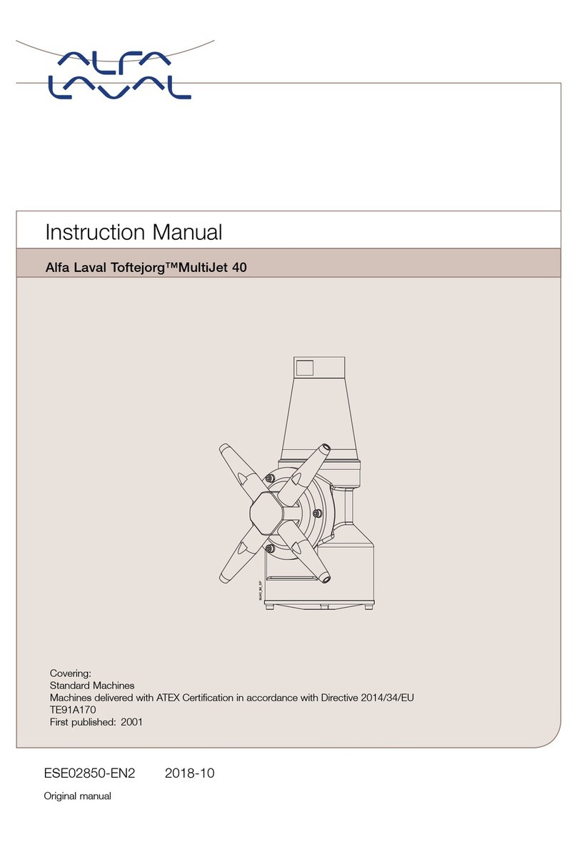
Alfalaval Toftejorg MultiJet 40 User manual

Instruction Manual
Toftejorg MultiJet 40
IM-TE91A170-EN041
ï
Return to menu

Instruction Manual, Toftejorg MultiJet 40 Page 1
IM-TE91A170-EN041
Contents
Contents.................................................................................................................... 1
Introduction ............................................................................................................... 3
General Description .................................................................................................. 4
Functioning..........................................................................................................................4
Standard Configurations .....................................................................................................5
Technical Data.......................................................................................................... 6
Installation and Normal Operation ............................................................................ 8
General Installation Instructions..........................................................................................8
Normal operation.................................................................................................................9
Maintenance and Repair......................................................................................... 10
Preventive Maintenance....................................................................................................10
Top Assembly ...................................................................................................................12
Bottom Assembly..............................................................................................................14
Hub Assembly...................................................................................................................16
Stem Assembly.................................................................................................................18
Gear Assembly..................................................................................................................20
Replacement of Collar Bushes..........................................................................................22
Replacement of Ball Races...............................................................................................24
Replacement of Main Collars............................................................................................26
Tools ....................................................................................................................... 28
Standard Tool kit for Toftejorg MultiJet 40........................................................................28
Sketch of tools for replacement of Main collars ................................................................29
Trouble Shooting Guide.......................................................................................... 30
Symptom: Slow rotation or failure of machine to rotate ....................................................30
Reference List of Parts, Toftejorg MultiJet 40......................................................... 32
Cross Sectional Drawing, Toftejorg MultiJet 40...................................................... 33
Standard Spare Parts Kit ........................................................................................ 34
How to order Spare Parts and Claim Procedure..................................................... 35
How to contact Alfa Laval Tank Equipment A/S ..................................................... 35
Service Card ........................................................................................................... 36
Claim Report Working Conditions........................................................................... 37
ï
Return to menu

Instruction Manual, Toftejorg MultiJet 40 Page 3
IM-TE91A170-EN041
Introduction
This manual has been prepared as a guide for the persons who will be operating and maintaining your
tank cleaning machine. The key to long life for your tank cleaning machine will always be a system of
carefully planned maintenance; you will appreciate that a tank cleaning machine which has a rough
and dirty job to do will need more frequent attention than one working in ideal conditions.
It is in your own interest to get the best and most economical performance from your tank cleaning
machine. Neglect of maintenance means poor performance, unscheduled stoppages, shorter life and
expense. Good maintenance means good performance, no unscheduled stoppages and better total
economy.
You will find the information contained in this manual simple to follow, but should you require further
assistance, our Customer Service Department and world-wide net of Distributors will be pleased to
help you. Please quote the type and serial number with all your enquiries; this will help us to help you.
The type and serial number are placed on the Body of the tank cleaning machine.
Note: The illustrations and specifications contained in this manual were effective at the date of printing.
However, as continuous improvements are our policy, we reserve the right to alter or modify any unit
specification on any product without prior notice or any obligation.
ï
Return to menu

Instruction Manual, Toftejorg MultiJet 40 Page 4
IM-TE91A170-EN041
General Description
The Toftejorg MultiJet 40 is a media driven and media lubricated tank cleaning machine. As it is self-
lubricating, there are no lubricating substances such as oil grease etc. in the machine which need to be
regularly changed.
Functioning
The flow of the cleaning fluid passes through a guide and a turbine, which accordingly is set into
rotation. The turbine rotation is through a gearbox transformed into a combined horizontal rotation of
the machine body and a vertical rotation of the nozzles.
The combined motion of the machine body and the nozzles ensures a fully indexed tank cleaning
coverage. After 5 5
/8revolutions of the Hub with nozzles (5 3
/8revolutions of the machine body) one
coarse cleaning pattern is laid out on the tank surface. During the following rounds, this pattern is
repeated 7 times, each of which is displaced 1/8 of the mesh in the pattern. After a total of 45 revolutions
of Hub with nozzles (43 revolutions of the machine body), a complete cleaning pattern has been laid out,
and the first pattern is repeated.
First cycle Full pattern
The speed of rotation of the turbine depends on the flow rate through the machine. The higher the flow
rate the higher the speed of rotation will be. In order to control the RPM of the machine for a wide
range of flow rates, the efficiency of the turbine can be changed (100% and 0% Turbine/Inlet guide).
Apart from the jet flow through the nozzles, fluid is leaking through the top of the machine, at the hub
and through the bottom cover. The leakage between the moving parts at the top and at the hub are
cleaning the gabs and thus preventing build-up of material that might cause the friction. The flow
through the bottom cover is due to the fact that the machine is media lubricated and that accordingly a
flow through the gearbox is needed.
ï
Return to menu

Instruction Manual, Toftejorg MultiJet 40 Page 5
IM-TE91A170-EN041
General Description (Continued)
Standard Configurations
Connection Guide Nozzles (mm)
(½" thread conn.) Article No.
100%
4 x ø6
4 x ø7
4 x ø8
TE21D138
TE21D140
TE21D142
NPT thread
0% 4 x ø8 TE21D160
100% 4 x ø6
4 x ø7
4 x ø8
TE21D238T
TE21D240
TE21D242
BSP thread
0% 4 x ø8 TE21D260
The machine is equipped with a clutch in the hub, which gives the possibility of rotation by hand the
nozzles, when the machine is to be lifted out through a tank opening.
ï
Return to menu

Instruction Manual, Toftejorg MultiJet 40 Page 6
IM-TE91A170-EN041
Technical Data
Weight of machine : 6,1 kgs (13,6 lb)
Working pressure : 3-12 bar (45-175 psi)
Recommended inlet pressure : 3-8 bar (45-120 psi)
Working temperature max. : 950C (200 F)
Materials : Stainless steel AISI 316 and 316L, Tefzel 200, PEEK, Viton,
ACO212CF, Teflon TFM
Principal dimensions in mm
ï
Return to menu

Instruction Manual, Toftejorg MultiJet 40 Page 7
IM-TE91A170-EN041
Technical Data (Continued)
Flow rate Throw length
Cleaning Time, f. complete Pattern (= 8 cycles)
ï
Return to menu

Instruction Manual, Toftejorg MultiJet 40 Page 8
IM-TE91A170-EN041
Installation and Normal Operation
General Installation Instructions
The tank cleaning machine should be installed in a vertical position (upright or upside down). It is
recommended to install a filter in the supply line in order to avoid large particles to clog inside the
machine. Before connecting the machine into the system, all supply lines and valves should be flushed
to remove foreign matter.
For devices with tapered thread connections to the down pipe, it is recommended that you secure the
connection in a manner appropriate for the application. Subject to the intended use environment and
any inhouse user requirements or policies, an adhesive such as Loctite No. 242 or equivalent could be
used. Other methods could be acceptable and subject to customer preference.
Note:The machine shall be installed in accordance with national regulations for safety and other
relevant regulations and standards.
Precautions shall be made to prevent starting of the cleaning operation, while personnel are inside the
tank or otherwise can be hit by jets from the nozzles.
In EU-countries the complete system must fulfil the EU-machine directive and shall be CE-marked.
Warning:If the machine is used in potential explosive atmospheres, tapes or joint sealing
compounds which are electrical insulators must not be used on threads or joints, unless
an electrical connection is otherwise established to ensure an effective earthing. In
addition, connecting pipe work must be electrically conductive and earthed to the tank
structure. The resistance between the nozzles and the tank structure should not exceed
20,000 Ohm.
This is essential to avoid the build-up of static electricity on the machine.
For further information see CENELEC R044-001 Safety of Machinery, guidance and
recommendations for the avoidance of hazards due to static electricity.
The machine as delivered has been tested at the factory before shipping. For transportation reasons,
the nozzles have been removed prior to shipment. Before installation and use, the nozzles should be
attached and secured appropriately for the application intended.
Check that the machine is in operating condition by inserting hex Screwdriver (tool No. TE134A) in
screw in top of Turbine shaft and easily turn Turbine shaft clockwise. If any resistance is recognised,
the machine should be disassembled to localise the cause.
ï
Return to menu

Instruction Manual, Toftejorg MultiJet 40 Page 9
IM-TE91A170-EN041
Installation and Normal Operation (Continued)
Normal operation
Cleaning Media
Use only cleaning media compatible with Stainless Steel AISI 316 and 316L, Tefzel 200, Viton, Teflon
TFM, ACO212CF and PEEK. Please note that PEEK is not resistant to concentrated sulfuric acid.
Please note that Viton is not resistant to a number of organic solvents as esters, ethers and ketones.
Normal detergents, moderate solutions of acids and alkalics will be acceptable. Aggressive chemicals,
excessive concentrations of chemicals at elevated temperatures as well as hydrochlorides should be
avoided. If you are in doubt, contact the local Alfa Laval Tank Equipment sales office.
After Use Cleaning
After use flush the machine with fresh water. Cleaning solutions should never be allowed to dry or set-
up in the system due to possible "salting out" or "scaling" of the cleaning ingredient. If cleaning media
contains volatile chloride solvents, it is recommended not to flush with water after use, in case this can
create hydrochloric acid.
Pressure
Avoid hydraulic shocks. Put on pressure gradually. Do not exceed 12 bar inlet pressure.
Recommended inlet pressure appears from Technical Data (page 6-7). High pressure in combination
with high flow rate will increase consumption of wear parts.
ï
Return to menu

Instruction Manual, Toftejorg MultiJet 40 Page 10
IM-TE91A170-EN041
Maintenance and Repair
Preventive Maintenance
In order to keep your tank cleaning machine servicing you as an efficient tool in your tank cleaning
operations, it is essential to maintain its high performance by following a simple preventive
maintenance programme, which will always keep your tank cleaning machine in good condition.
Good maintenance is careful and regular attention!
The following recommended preventive maintenance is based on tank cleaning machines working in
average conditions. However, you will appreciate that a tank cleaning machine, which has a rough and
dirty job to do, will need more frequent attention than one working in ideal conditions. We trust that you
will adjust your maintenance programme to suit.
Always use only proper tools. Use standard tool kit. Never force, hammer or pry components together
or apart. Always perform all assembly/disassembly steps in the order described in this manual.
Never assemble components without previous cleaning. This is especially important at all mating
surfaces. Work in a clear well lighted work area.
Every 300 working hours
1. Disassemble machine as described on the following pages.
2. Clean material build-up and deposits from internal parts with Scotch-brite, S-Ultrafine, eventually
chemical cleaner and fine abrasive cloth.
3. Check Slide bearings (pos. 28 on the cross sectional drawing, page 33) for wear. If hole is worn
oval to max. diameter more than 10.4 mm, Slide bearings should be replaced. If end face of Slide
bearing is worn more than x mm into Slide bearing, it should be replaced.
Under Turbine shaft : x = 1.5 mm
At Horizontal shaft : x = 0.5 mm
4. Check Collar bushes (pos. 10) in Gear frame. If holes are worn oval to max. diameter more than
13.4 mm, Collar bush should be replaced. How to replace Collar bushes, see page 22.
Note: Timely replacement of Slide bearings and Collar bushes will prevent costly damage to the
gear box.
ï
Return to menu

Instruction Manual, Toftejorg MultiJet 40 Page 11
IM-TE91A170-EN041
Maintenance and Repair (Continued)
Preventive Maintenance
5. Check Worm wheels (pos. 11 and pos. 33). If extremely worn, they should be replaced.
6. Check Main bush (pos. 5). If worn it should be replaced.
7. Assemble machines as described in the following pages.
8. Check that the machine is in operating condition by inserting 3/16” hex Screwdriver (tool No.
TE134A) in screw in top of Turbine shaft and easily turn Turbine shaft clockwise. If any resistance
is recognised, the machine should be disassembled to localise the cause.
Apart from the parts specifically mentioned above, all the remaining wear parts should regularly be
inspected for wear. Which parts that are wear parts appear from Reference List of Parts, page 32.
Service Card
For your registration of maintenance carried out, fill in service card which you will find at the back of
this manual.
ï
Return to menu

Instruction Manual, Toftejorg MultiJet 40 Page 12
IM-TE91A170-EN041
Maintenance and Repair (Continued)
Top Assembly
Disassembly
1. Remove Screws (pos. 17). Loosen and unscrew with a socket wrench (tool No. TE462A).
2. Lift off Top Cone (pos. 1).
3. Remove Guide /Guide ring (pos. 2). The Guide has a groove in the outer diameter. The Guide is
easily lifted out of the Stem by means of two ordinary Screwdrivers inserted into the groove.
4. Remove Screw (pos. 15), Spring washer (pos. 16) and Washer (pos. 13). To secure Impeller
against rotation, insert carefully Screwdriver (tool No. TE134A), through Impeller (pos. 4) into a
hole in the Stem.
5. Pull off Impeller (pos. 4).
Reassembly
1. Reinstall Impeller (pos. 4). Make sure that Impeller is correctly rotated to be pushed onto Turbine
shaft. Do not try to hammer Impeller in position, as this will damage Slide bearing under Turbine
shaft.
2. Mount Washer (pos. 13), Spring washer (pos. 16) and Screw (pos. 15) and tighten. To secure
Impeller against rotation insert carefully Screwdriver (tool No. TE134A) through Impeller (pos. 4)
into a hole in the Stem.
3. Reinstall Guide /Guide ring (pos. 2).
4. Mount Top Cone (pos. 1). Make sure that it is in correct position over Guide/Guide ring (pos. 2)
Rotate Top cone to align holes in Top cone and Stem.
5. Mount and tighten Screws (pos. 17) with a socket wrench (tool No. TE462A).
ï
Return to menu

Instruction Manual, Toftejorg MultiJet 40 Page 13
IM-TE91A170-EN041
Maintenance and Repair (Continued)
Top Assembly
ï
Return to menu

Instruction Manual, Toftejorg MultiJet 40 Page 14
IM-TE91A170-EN041
Maintenance and Repair (Continued)
Bottom Assembly
Disassembly
1. Turn machine upside down.
2. Remove Screws (pos. 31) from Bottom cover (pos. 30).
3. Remove Bottom cover (pos. 30) and Gasket (pos. 32).
4. Remove Screws (pos. 15) in Bearing cover (pos. 14). Carefully push out Turbine shaft (pos. 6)
from opposite end. Do not try to hammer out Turbine shaft, since this can damage Slide bearing
and O-ring.
5. Check O-ring (pos. 35) and replace if worn.
6. Remove Screws (pos. 15) and Spring Washers (pos. 16) along the circumference of Gear frame
(pos. 29). Turn Gear frame about 1 cm (½”). Draw out Gear Subassembly (holes in Gear frame are
excellent for holding Gear Subassembly).
Reassembly
1. Reinsert Gear subassembly in bottom of machine body. Turn Gear Frame (pos. 29) to align holes
in Gear frame and 3/16” threads in body. Mount Spring washers (pos. 16) and Screws (pos. 15)
along circumference of Gear frame (pos. 29). Tighten screw crosswise.
Note: To secure meshing between Gear wheel (pos. 7) and Pinion (pos. 9). It might be
necessary to rotate slightly either the whole Gear Subassembly or the Gear wheel.
2. Reinsert Turbine shaft (pos. 6) with Slide bearing carefully through Gear wheel (pos. 7). Push
carefully Slide bearing (pos. 28) into position. Mount Bearing cover (pos. 14) with Screws (pos.
15). Tighten crosswise.
3. Place Bottom gasket (pos. 32) and Bottom cover (pos. 30).
4. Mount Screws (pos. 31) and tighten crosswise.
ï
Return to menu

Instruction Manual, Toftejorg MultiJet 40 Page 15
IM-TE91A170-EN041
Maintenance and Repair (Continued)
Bottom Assembly
ï
Return to menu

Instruction Manual, Toftejorg MultiJet 40 Page 16
IM-TE91A170-EN041
Maintenance and Repair (Continued)
Hub Assembly
Disassembly
1. Remove Nozzles (pos. 20). Nozzles are untightened with a wrench on the faces of the Nozzles.
2. Remove Screws (pos. 31), Hub cover (pos. 19), and Hub gasket (pos. 25).
3. Draw out Hub (pos. 21) together with Ball retainer with balls (pos. 24) and Bevel gear (pos. 18).
4. Check Lip seal (pos. 37). If it is worn it should be replaced.
If Ball races (pos. 18.1 and 19.1) in Hub cover and in Bevel gear are extremely worn, they should be
replaced as well as the Ball retainer with balls (pos. 24). How to replace Ball races see page 24.
Reassembly
1. Carefully replace Lip seal (pos. 37) in the Hub (pos. 21).
2. Slide on Hub (pos. 21). Reinsert Bevel gear with race (pos. 18) and Ball retainer with balls (pos.
24).
3. Mount Hub gasket (pos. 25) and Hub cover with race (pos. 19), and set with Screws (pos. 31).
4. Screw on Nozzles (pos. 20) and tighten with wrench.
ï
Return to menu

Instruction Manual, Toftejorg MultiJet 40 Page 17
IM-TE91A170-EN041
Maintenance and Repair (Continued)
Hub Assembly
ï
Return to menu

Instruction Manual, Toftejorg MultiJet 40 Page 18
IM-TE91A170-EN041
Maintenance and Repair (Continued)
Stem Assembly
Disassembly
1. Place machine in upside-down position.
2. Remove Screws (pos. 15) in Gear wheel (pos. 7). To prevent rotation of Stem (pos. 3) mount two
screws in two holes opposite one another in BIG end of Stem. Place Stem in a vice held by the
heads of the two screws.
3. Draw out Gear wheel with ball races (pos. 7) and Ball retainer with balls (pos. 24).
4. Push out Stem (pos. 3).
5. Check O-ring on Stem (pos. 36) and O-ring in Upper collar main (pos. 34). Replace if worn.
6. If worn, press out Main bush (pos. 5).
If Ball races in Body (pos. 26.3) and on Gearwheel (pos. 7.1) are extremely worn they should be
replaced together with Ball retainer with balls (pos. 24). How to replace Ball races see page 24.
Reassembly
1. If replaced press Main bush (pos. 5) into Stem (pos. 3).
2. Push carefully Stem into Body. Turn machine upside-down.
3. Place Ball retainer with balls (pos. 24) and Gear wheel (pos. 7) into Body on Ball race. Rotate
Gearwheel to check free rotation. Mount Gearwheel with Screws (pos. 15) and tighten crosswise.
To prevent rotation of Stem (pos. 3) mount two screws in two holes opposite one another in BIG
end of Stem. Place Stem in a vice held by the heads of the two screws.
ï
Return to menu

Instruction Manual, Toftejorg MultiJet 40 Page 19
IM-TE91A170-EN041
Maintenance and Repair (Continued)
Stem Assembly
ï
Return to menu

Instruction Manual, Toftejorg MultiJet 40 Page 20
IM-TE91A170-EN041
Maintenance and Repair (Continued)
Gear Assembly
Disassembly
1. To make a backstop, remount Turbine shaft (pos. 6) with Slide bearing (pos. 28) and O-ring (pos.
35) into Gear frame (pos. 29). Mount Bearing cover (pos. 14) with Screws (pos. 15).
2. Hold Turbine shaft (pos. 6) against 1st stage Worm wheel (pos. 33) with one hand and loosen
Screws (pos. 15) in Pinion (pos. 9) and Horizontal shaft (pos. 27) with the other hand.
3. Remove Screws (pos. 15) in Bearing cover (pos. 14) and take out Turbine shaft (pos. 6).
4. Draw out Horizontal shaft (pos. 27) and 1st stage Worm wheel (pos. 33) after removal of Screw
(pos. 15), Spring washer (pos. 16) and Washer (pos. 13).
5. Draw out Pinion (pos. 9) and 2nd stage Worm wheel (pos. 11), also freeing Journal (pos. 12) after
removal of Screw (pos. 15), Spring washer (pos. 16) and Washer (pos. 13).
6. Remove Bearing cover (pos. 14) and Slide bearing (pos. 28) after removal of Screw (pos. 15).
7. Remove Screw (pos. 15), Spring washer (pos. 16), Washer (pos. 13) and Slide bearing (pos. 28)
and O-ring (pos. 35) from Turbine shaft (pos. 6). Use faces on Turbine shaft to hold against
rotation.
Warning:Do not damage driver faces on Turbine shaft. Use only proper tools providing a
firm grip such as a wrench or a vice.
How to replace Collar bushes (pos. 10), see page 22.
Reassembly
1. Mount O-ring (pos. 35) and Slide bearing (pos. 28) carefully on Turbine shaft (pos. 6) and secure
with Washer (pos. 13), Spring washer (pos. 16) and Screw (pos. 15). Hold Turbine shaft in a vice
or with wrench on driver faces and tighten.
2. Push Slide bearing (pos. 28) for Horizontal shaft (pos. 27) into Gear frame (pos. 29) and fix
Bearing cover (pos. 14) with Screws (pos. 15). Tighten crosswise.
3. Insert 2nd stage Worm wheel (pos. 11), Pinion (pos. 9) and Journal (pos. 12). Mount Washer (pos.
13), Spring washer (pos. 16) and fix with Screw (pos. 15). Check rotation.
ï
Return to menu
Other manuals for Toftejorg MultiJet 40
1
Table of contents
Other Alfalaval Other manuals

Alfalaval
Alfalaval Toftejorg SaniMega User manual

Alfalaval
Alfalaval Toftejorg MultiJet 65 User manual

Alfalaval
Alfalaval Toftejorg TZ-74 User manual

Alfalaval
Alfalaval Toftejorg MultiJet 25 User manual

Alfalaval
Alfalaval Toftejorg MultiJet 25 User manual

Alfalaval
Alfalaval Toftejorg User manual

Alfalaval
Alfalaval Gunclean Toftejorg T-82 User manual

Alfalaval
Alfalaval Alfie User manual

Alfalaval
Alfalaval Toftejorg TZ-74 User manual

Alfalaval
Alfalaval BladeClean User manual