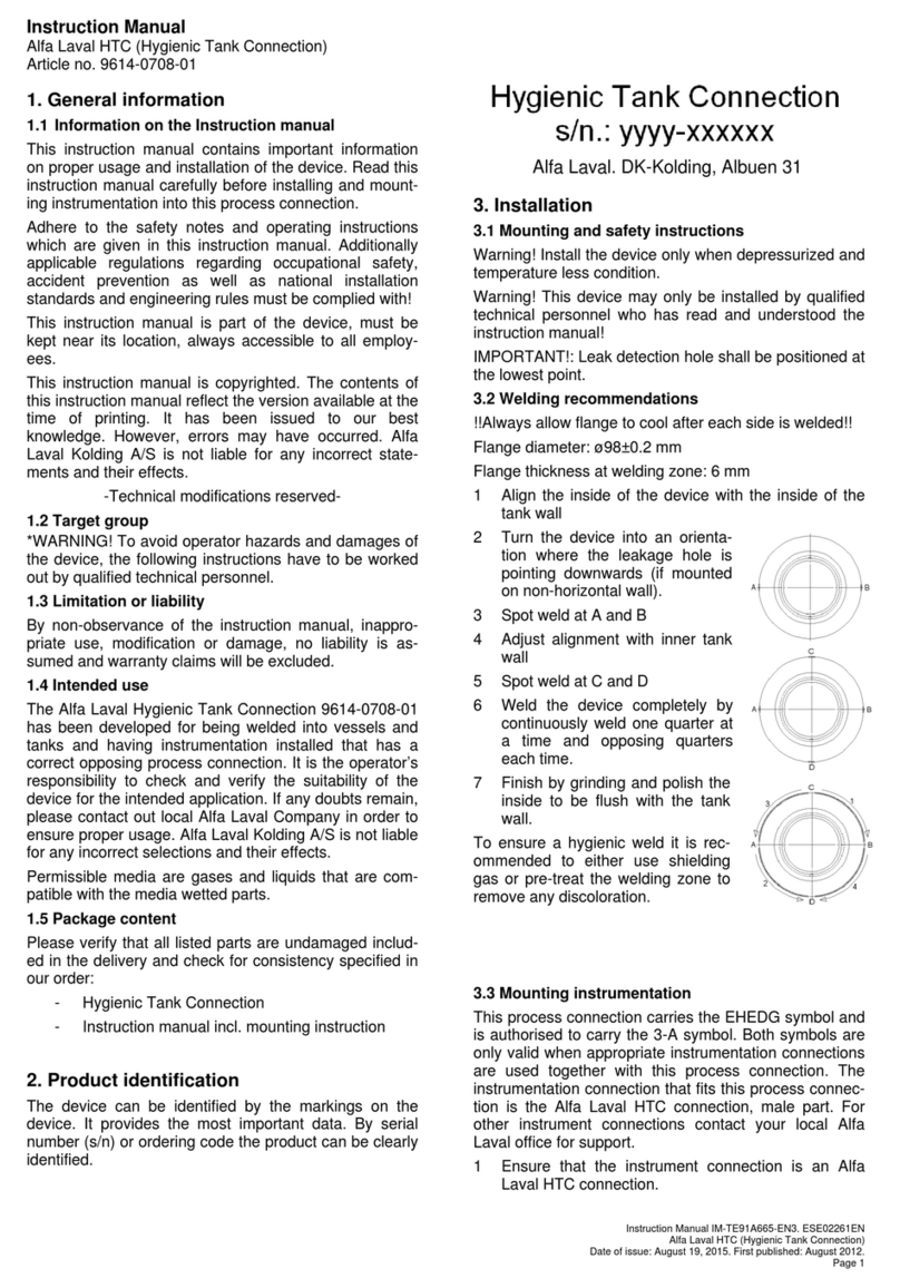
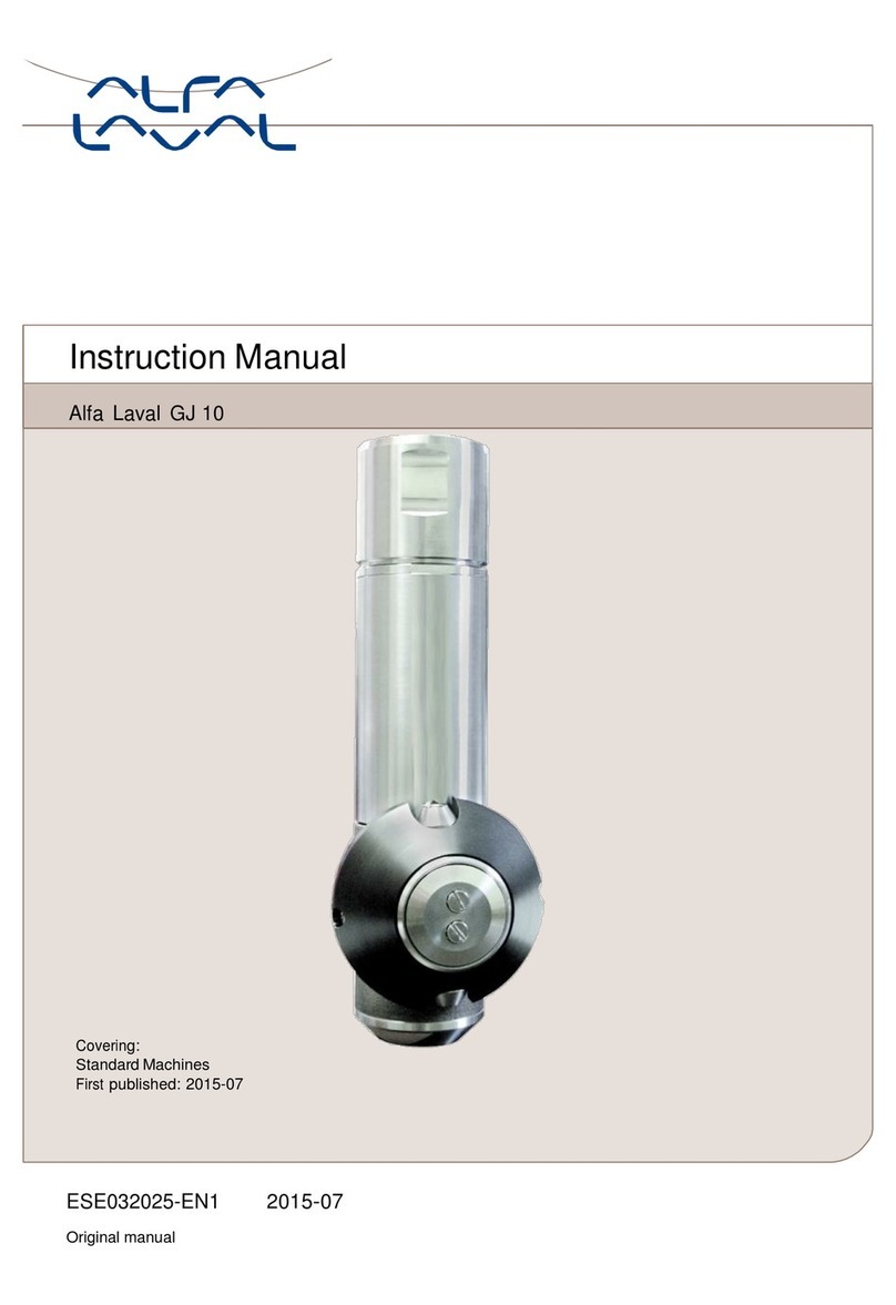
Alfalaval Toftejorg SaniJet 20 User manual

4107-0143
Covering: Standard, Hastelloy
Q-doc: Equipment Doc (3.1 Inspection Certificate - EN 10204)
Q-doc+FAT-SAT: Qualification Documentation incl. FAT and SAT)
Improved surface finish (0.5 µm Ra internal/external media contact parts)
Machines delivered with ATEX/IECEx Certification in accordance with Directive 2014/34/EU
First published: 04-2009
ESE01829-EN13 2019-07
Original manual
Instruction Manual
Alfa Laval Toftejorg™ SaniJet 20 Air Driven


Table of contents
The information herein is correct at the time of issue but may be subject to change without prior notice
1. EC/EU Declaration of Conformity .................................................................. 5
2. Safety .................................................................................................... 6
2.1. Important information ............................................................................. 6
2.2. Warning signs ..................................................................................... 6
3. Introduction ............................................................................................ 7
3.1. Introduction ........................................................................................ 7
3.2. Intended Use ...................................................................................... 7
3.3. Patents and Trademarks ......................................................................... 8
3.4. Reserved rights for design changes ............................................................ 8
3.5. Marking ............................................................................................ 8
3.6. ATEX/IECEx marking ............................................................................. 9
3.7. ATEX/IECEx temperature class and code ...................................................... 11
3.8. Quality system .................................................................................... 12
4. Installation .............................................................................................. 13
4.1. General description ............................................................................... 13
4.2. Functioning ........................................................................................ 14
4.3. Installation of Air Motor ........................................................................... 17
4.4. General safety and installation instructions ..................................................... 19
4.5. Specific conditions for safe use in accordance with ATEX/IECEx certification .............. 20
5. Operation ............................................................................................... 23
5.1. Normal operation ................................................................................. 23
5.2. Normal Operation of Air Motor .................................................................. 24
5.3. Safety Precautions ................................................................................ 25
6. Maintenance ........................................................................................... 26
6.1. Preventive Maintenance .......................................................................... 26
6.2. Reserved rights for design changes of Alfa Laval equipment used in validated processes 26
6.3. Preventive Maintenance of Air Motor ........................................................... 27
6.4. Service and repair of ATEX/IECEx certified machines ......................................... 28
6.5. Service and repair of machines ordered with Q-doc and with Q-doc + FAT-SAT .......... 29
6.6. Every 300 working hours ......................................................................... 30
6.7. Cleaner Head Unit - dismantling and reassembling ........................................... 31
6.8. Base Unit - Dismantling and Reassembling .................................................... 32
6.9. Air Motor Drive Unit - dismantling and reassemebling ........................................ 33
6.10.Rotacheck System ............................................................................... 34
7. Trouble shooting guide ............................................................................... 35
8. Technical data ......................................................................................... 36
9. Product programme .................................................................................. 40
9.1. Standard configurations .......................................................................... 40
9.2. Available add-ons ................................................................................. 42
9.3. Available add-ons for spare parts ............................................................... 43
9.4. Accessories ....................................................................................... 43
10. Parts drawings and lists, service kits and tools ................................................. 44
10.1.Toftejorg SaniJet 20, Air Driven (EPDM as standard) .......................................... 44
10.2.Toftejorg SaniJet 20 Air Driven improved surface finish (EPDM as standard) ............... 46
3

Table of contents
The information herein is correct at the time of issue but may be subject to change without prior notice
10.3.Toftejorg SaniJet 20 Air Driven Hastelloy (FFKM as standard) ................................ 48
10.4.Toftejorg SaniJet 20 Air Driven Hastelloy improved surface finish (FFKM as standard) .... 50
10.5.Service kits ........................................................................................ 52
10.6.Tools ............................................................................................... 53
11. General information ................................................................................... 54
11.1.Service and repair ................................................................................ 54
11.2.How to order spare parts ........................................................................ 54
11.3.How to contact Alfa Laval Kolding A/S ......................................................... 54
4

1 EC/EU Declaration of Conformity
The Designated Company
Alfa Laval Kolding A/S
Company Name
Albuen 31, DK-6000 Kolding, Denmark
Address
+4579322200
Phone No.
hereby declare that
Tank Cleaning Machine
Designation
Alfa Laval Toftejorg SaniJet 20 Air Driven
Type
From serial number 2019-0001 to 2030-99999
is in conformity with Machinery Directive 2006/42/EC and the following harmonized standard is used:
DS/EN ISO 12100:2011 Safety of Machinery - Risk Assessment
is in conformity with (Ex / ATEX) Directive 2014/34/EU and the following harmonized standards are used:
EN ISO 80079-36:2016, EN ISO 80079-37:2016, DS/EN ISO/IEC 80079-34:2011, Annex A, paragraph A.5.3 Rotating machines
SaniJet 20 A, Tank cleaning unit
EC Type Examination Certificate no. Baseefa05ATEX0117X and IECEx BAS 19.0063X
II 1G Ex h IIC 85ºC... 175ºCGa
Marking: II 1D Ex h IIIC T85ºC... T140ºCDa
The QAN (Quality Assurance Notification) is carried out by SGS Fimko Oy, Särkiniementie 3, Helsinki 00211, Finland. Notified Body No. 0598.
EU Type Examination Certification is carried out by SGS Fimko Oy, Särkiniementie 3, Helsinki 00211, Finland. Notified Body no. 0598.
IECEx Certificate of Conformity is carried out by Baseefa Ltd., Rockhead Business Park, Staden Lane, Buxton, Derbyshire SK17 9RZ, United
Kingdom. IECEx Accepted Certification Body (ExCB).
SaniJet 20 A, Air Motor Unit
Archive no.: DTI-2013-1-0148A
II 1G Ex h IIC T4 Ga
Marking: II 1D Ex h IIIC T135ºCDa
Archived at Danish Technological Institute, Certification body number 0396, Gregersensvej, 2630 Taastrup, Denmark
The person authorised to compile the technical file is the signer of this document.
Global Product Quality Manager
Pumps, Valves, Fittings and Tank Equipment Lars Kruse Andersen
Title Name Signature
Kolding 2019-07-01
Place Date (YYYY-MM-DD)
This Declaration of Conformity replaces Declaration of Conformity dated 2016-05-01
5

2 Safety
Unsafe practices and other important information are emphasized in this manual.
Warnings are emphasized by means of special signs.
Always read the manual before using the tank cleaning machine!
2.1 Important information
WARNING
Indicates that special procedures must be followed to avoid serious personal injury.
CAUTION
Indicates that special procedures must be followed to avoid damage to the tank cleaning machine
NOTE
Indicates important information to simplify or clarify procedures.
2.2 Warning signs
General warning:
ATEX/IECEx warning:
6

3 Introduction
Toftejorg SaniJet 20 Air driven
3.1 Introduction
This manual has been prepared as a guide for installation and for the persons who will be operating and maintaining your tank
cleaning machine. The key to long life for your tank cleaning machine is a carefully planned system for preventive maintenance;
you must appreciate that a tank cleaning machine which has a rough and dirty job to do will need more frequent attention than
one working under ideal conditions.
NOTE
Get the best and most economical performance from your tank cleaning machine. Insufficient preventive maintenance means
poor performance, unscheduled stops, shorter lifetime and extra costs. Good preventive maintenance on the contrary means
good performance, no unscheduled stops and superior total economy.
Should you require further assistance, our Technical Sales Support department and worldwide net of sales offices will be pleased
to help you. Please quote the type, article and serial numbers with all of your enquiries; this helps us to help you. The type,
article and serial numbers are laser engraved on the Base house of the tank cleaning machine. For more information on marking
position see section 3.5 Marking and 3.6 ATEX/IECEx marking.
Warning: Before installing the machine and setting it into operation carefully read the General safety and installation
instructions (page 19) and the specific conditions for safe use in accordance with ATEX/IECEx directive
2014/34/EU (page 20) and take all necessary precautions according to your application and local regulations.
NOTE
The illustrations and specifications contained in this manual were effective at the date of printing. However, as continuous
improvements are our policy, we reserve the right to alter or modify any unit specification on any product without prior notice or
any obligation.
The English version of the instruction manual is the original manual. We make reservations in regard to possible mistranslations in
language versions of the instruction manual. In case of doubt, the English version of the instruction manual applies.
3.2 Intended Use
It is to be verified by the end-user:
- that the tank cleaning machine is in conformity with respect to tank, vessel or container size in which it will be used.
- that the construction materials (both metallic and non-metallic) are compatibility with product, flushing media, cleaning
media, temperatures and pressure under the intended use.
The tank cleaning machine mixer is intended for use in closed tank, vessel or container. If used in open environment see
4.4 General safety and installation instructions (page 19).
7

3 Introduction
Toftejorg SaniJet 20 Air driven
3.3 Patents and Trademarks
This Instruction Manual is published by Alfa Laval Kolding A/S without any warranty. Improvements and changes to this
Instruction Manual may at any time be made by Alfa Laval Kolding A/S without prior notice. Such changes will, however,
be incorporated in new editions of this Instruction Manual.
Alfa Laval Kolding A/S. All rights reserved.
The Alfa Laval logotype is a trademark or a registered trademark of Alfa Laval Corporate AB. "Toftejorg" and “SaniJet” are
trademarks or registered trademarks of Alfa Laval Kolding A/S. The Toftejorg™ SaniJet 20 product has patents in the EPO
member states, in the US and in other countries. Other products or company names mentioned herein may be the trademarks
of their respective owners. Any rights not expressly granted herein are reserved.
3.4 Reserved rights for design changes
Alfa Laval is continuously working on improving our equipment and services. In this improvement work Alfa Laval may for
example change the design and material in our equipment. A change in the design will not necessarily entail a change of the
specification and item no. for the equipment.
Alfa Laval reserves the right to change the design of Alfa Laval equipment without any notifications for improvements of our
design.
If Equipment from Alfa Laval is used in connection with, for example, a validated plant, and an order for replacements is
made, the design of the replacement may have been changed even if the specifications /item no. is the same as the existing
installed and validated ones.
When ordering a replacement please contact Alfa Laval sales support in this matter before placing the order.
3.5 Marking
Alfa Laval tank cleaning machines are marked to allow for recognition of type of machine, machine name, serial number and
manufacturing address.
The marking is placed on the base house of the tank cleaning machine.
Serial number explanation
Machines supplied with or without standard documentation:
yyyy-xxxxx: serial number
yyyy: year
xxxxx: 5 digit sequential number
8

3 Introduction
Toftejorg SaniJet 20 Air driven
3.6 ATEX/IECEx marking
Cleaner unit
The Alfa Laval Toftejorg SaniJet 20A Cleaner unit is certified as category I component. The ATEX certification is carried out by
the Notified Body SGS Fimko Oy, who has issued the certificate no. Baseefa05ATEX0117X.
The IECEx certification is carried out by the Certification Body SGS Baseefa Ltd., who has issued the certificate no. IECEx BAS
19.0063X.
Note
Explosion protection type is constructional safety “c”.
The marking on the ATEX/IECEx certified Alfa Laval Toftejorg SaniJet 20 is as follows (for information on marking position
see next page):
Serial number explanation
Machines supplied with or without standard documentation:
yyyy-xxxxx: serial number
yyyy: year
xxxxx: 5 digit sequential number
Serial number explanation
Machines supplied with Q-doc + FAT-SAT documentation:
yyyy-FAT-SAT-xxx: serial number
yyyy: year
xxx: 3 digit sequential number
Drive unit
The Alfa Laval Toftejorg SaniJet 20A Air drive unit is certified as category 2 component for installation in zone 1/21 (outside tank)
in accordance with Directive 2014/34/EU. The certification is carried out by Alfa Laval as a Own Assessment and archived at
Certification body Teknologisk Institut. Registered as archive no.: DTI-2013-1-0148A.
The marking on the ATEX/IECEx certified Alfa Laval Toftejorg SaniJet 20A Air drive unit is as follows (for information on
marking position see next page):
9

3 Introduction
Toftejorg SaniJet 20 Air driven
Marking positions: 1. Drive unit
2. Cleaner unit
ATEX zone 1/21ATEX zone 0/20
1
2
4107-0150
A ( 3 : 1 )
27
4107-0151
A
A: For FAT-SAT machines with index no. -6x,
the s/n must be yyy-FAT-SAT-xxx
10

3 Introduction
Toftejorg SaniJet 20 Air driven
3.7 ATEX/IECEx temperature class and code
The maximum surface temperature depends mainly on operating conditions which are the temperature of the cleaning fluid and
the ambient temperature.
Group II EPL Ga
The gas temperature class is corrected with a safety margin of 80% due to a requirement for Group ll EPL Ga equipment.
The gas temperature class depends on the cleaning fluid temperature or the ambient temperature, whichever of the two is
the highest.
Table for determining temperature class (gas atmospheres)
Gas
Temperature class
Cleaning fluid temperature,
Tp(°C)
Ambient temperature,
Tamb (°C)
85°C (T6) ≤+68°C ≤+68°C
100°C (T5) ≤+80°C ≤+80°C
135°C (T4) ≤+108°C ≤+108°C
175°C ≤+140°C ≤+140°C
Group III EPL Da
The dust temperature class depends on the cleaning fluid temperature or the ambient temperature, whichever of the two is
the highest.
No dust layer is considered.
Table for determining temperature class (dust atmospheres)
Dust
Temperature code
Cleaning fluid temperature,
Tp(°C)
Ambient temperature,
Tamb (°C)
T85°C ≤+85°C ≤+85°C
T100°C ≤+100°C ≤+100°C
T135°C ≤+135°C ≤+135°C
T140°C ≤+140°C ≤+140°C
Example of gas class determination
Cleaning fluid temperature is 67°C and ambient temperature is 75°C.
Gas class = T5
ATEX/IECEx marking for the equipment SJ20A:
II 1G Ex h IIC 85°C…175°C Ga
II 1D Ex h IIIC T85°C…T140°C Da
ATEX marking for the equipment SJ20A - Air motor::
II 1G Ex h IIC T4 Ga
II 1D Ex h IIIC T135°C Da
11

3 Introduction
Toftejorg SaniJet 20 Air driven
3.8 Quality system
The Alfa Laval Toftejorg SaniJet 20 is produced according to Alfa Laval Kolding’s ISO 9001 International Standard certified
quality system. All parts are made from certified material and all non-metal parts are made from FDA and USP Class VI
approved materials.
12

4 Installation
Toftejorg SaniJet 20 Air driven
4.1 General description
The Alfa Laval Toftejorg SaniJet 20 is a tank cleaning machine intended for industrial use in closed tanks for processing storage
and transportation. There is a broad range of application areas within pharmaceutical, food and chemical industries.
The Alfa Laval Toftejorg SaniJet 20 is a hygienic cleaning device of the rotary jet head type for permanent installation that provides
a 360° indexed cleaning pattern. Provided it is installed in an upright position, the Alfa Laval Toftejorg SaniJet 20 is completely
self-cleaning and self-draining, and it has an integrated self-cleaning down pipe (patent pending). The drive mechanism is located
outside the tank or process equipment, leaving a minimum of parts to be submerged into the product. All product contact
surfaces are AISI 316/316L, duplex SAF 2205, Ti, Hastelloy C22/C276 stainless steel and USP Class VI and FDA approved
polymer materials such as PEEK, EPDM, Viton and FFKM.
No threads or screws have been used in the product contact areas.
The cleaning device is lubricated by the cleaning media. No oil, grease or other lubricants are used.
The Alfa Laval Toftejorg SaniJet 20 is available in media driven or air motor driven versions. The air motor driven version is
equipped with a magnetic clutch providing a leakage-proof transmission and provide an effective drive for low flow machines
in rough environments. The air motor has variable speed in order to adjust cleaning intensity. The media version is covered by
Instruction Manual IM-TE91A792.
The Alfa Laval Toftejorg SaniJet 20 is designed for use in pharmaceutical, biotechnological, food and dairy processing applica-
tions. Tanks and vessels between 0.5-30 m3(130-8,000 US gallons). The design makes the Alfa Laval Toftejorg SaniJet 20
especially well suited when processing high viscous, foaming or thixotropic products and in chemical processing applications,
where product cross contamination is unacceptable and must be avoided.
For use in explosive hazard zones the ATEX/IECEx version can be used, provided it is installed according to safety instructions
in local regulations.
13

4 Installation
Toftejorg SaniJet 20 Air driven
4.2 Functioning
Alfa Laval Toftejorg SaniJet 20 consists of 3 main parts: The Drive unit with flow inlet and the Base housing placed outside the
tank, and inside the tank: the Down pipe with the rotating Outer tube and the Cleaner unit.
The flow of the cleaning fluid passes from the inlet through the Base housing,
through the Down pipe, into the Cleaner head and out through the Nozzles. The
Outer tube of the Down pipe is rotably suspended on a Stationary shaft with a Ball
bearing inside the Outer tube. The Drive mechanism rotates the Outer tube with
the Cleaner unit around the vertical axis. Via a set of Bevel gears on the Stationary
shaft and the Cleaner head, the Cleaner head with the Nozzles is simultaneously
rotated around the horizontal axis in a fixed relation thus moving the nozzles and
the jets 360°around in the tank making a pre-set indexed cleaning pattern.
The Alfa Laval Toftejorg SaniJet 20 utilises the patented “Golden Section” cleaning pattern. The distance between the tracks
of the jets ensures an efficient removal of remaining product from the tank surface right from the beginning of the cleaning
sequence, allowing for short cleaning time.
Example - 2 nozzle machine:
TD523451
TD523452 TD523453
0.8 min. 2.3 min. 6 min.
The time needed to perform a proper cleaning depends on type of soilage, distance, cleaning procedure and agent. For sub-
stances that are easily mobilised, i.e. are easy to remove, less than 1 min. could be sufficient while in cases of more heavy soilage
(high viscous, sticky substances, etc.) a more dense pattern/longer time will be needed.
14

4 Installation
Toftejorg SaniJet 20 Air driven
Machine with external motor drive
The machine is driven by a gear motor mounted on top of the Inlet housing. Via a Magnetic clutch the rotation of the gear motor
is transmitted from the outside through a closed wall to the Output shaft placed inside the Inlet housing. The Output shaft is in
mesh with the Down pipe and rotates the Down pipe in the same way as in the media driven version.
A: Gear Motor
B: Cup-shaped closed wall
C: Output shaft
A
B
C
*Note
4107-0037
*Note: Motor driven version with magnetic
clutch
The output shaft of the gear motor is equipped with a Rotor with permanent magnets. The rotor is placed inside the cavity in the
Motor flange, made by the cup protruding into the liquid chamber in the Inlet housing. The cup is welded to the motor flange as
a hermetic sealed closed wall between the liquid chamber and the outside. The magnetic field from the permanent magnets is
transferred through the wall, to a ring with permanent magnets inside the Output shaft, which is placed around the cup on the
inside the liquid chamber.
A: Motor flange
B: Rotor with magnets
C: Cup-shaped colosed wall
D: Ring with magnets inside Output shaft
A
B
C
D
4107-0038
The machine with Air motor is equipped with a flow regulator to make the speed adjustable between approx. 3 and 14 RPM.
15

4 Installation
Toftejorg SaniJet 20 Air driven
Self-cleaning
Apart from the main flow flushing the inside of the Base housing and the Down pipe, and thereafter forming the jets through the
Nozzles, fluid is flushed through all internal cavities, through Bevel gear, Ball bearings and gabs between moving parts and is
finally also used for cleaning of the outside surfaces of the machine. From the gab between the Base housing and the rotating
Down pipe, a cleaning jet is directed against the Down pipe, thus loosening and removing product remains on the outside. A
liquid film flushing all around the tube further assists by continuously transporting away loosened product remains. The front of
the Cleaner head is flushed by a liquid flow from the gab between the Cleaner head and the Retaining ring.
In order to ensure a proper self-cleaning, the machine must be installed in an approx. upright position and the inlet pressure
must be min. 3 bar. In the bottom of the Cleaner head, in the Retaining ring, the machine is equipped with a hole to ensure
self-draining. This self-draining is only ensured, if the machine is installed in an upright position.
Cleaning Pattern, The Golden Section
The patented Golden Section cleaning pattern (EP-Patent No.: 0495883. US-Patent No.: 5,279.675) is unique in building up
the pattern in an ultimate uniform way. The pattern starts very coarse and refines itself in a step-less way by laying out the
tracks approximately in the middle between the two most distant tracks already made. This means that the jets always clean
the areas containing most remaining product, and thereby remove as much deposit as possible in the shortest possible way.
In case a complete cleaning pattern is not required, it will be possible to reach the same cleaning level within half the time and
by using half the amount of cleaning fluid compared to a traditional step-wise cleaning pattern. Furthermore, due to the uniform
cleaning pattern, the cleaning can be stopped at any time, whereas with traditional non-uniform cleaning pattern this would not
be advantageous. However, after the complete cleaning pattern has been established, the difference between the Golden
Section and the traditional stepwise cleaning pattern is negligible.
Golden Section - Cleaning pattern Traditional - Cleaning pattern
TD523454 TD523455
16

4 Installation
Toftejorg SaniJet 20 Air driven
4.3 Installation of Air Motor
Important information
Recommended inlet air pressure is not to exceed 6 bar (87) psi maximum. It is recommended to use an air filter and moisture
trap on inlet air supply to avoid contamination being fed into air motor.
General information
The air motor is designed to be driven by compressed air and under no circumstances be driven with any other gases.
Fluids, particles, solids or any substances mixed with air, particularly combustible substances likely to cause explosions,
must not drive air motor.
Warning: Do not drive with flammable or explosive gases.
Warning: Air motor is designed for air only. Do not allow corrosive gases or particulate material to enter motor. Water vapor,
oil-based contaminants, or other liquids must be filtered out.
Warning: Do not use a hammer or force coupling or drive pulley onto shaft when installing drive onto air motor. This causes
end thrust that could damage air motor.
Note: Ambient temperature outside tank should not exceed +40°C (140°F)
Installation
Install a moisture trap and filter in air line ahead of motor. For efficiency of output and control of speed, use air lines of
same size or in next pipe size larger than intake port of motor. As inlet line a ø8/5.5 tube should be used (customer supply).
As standard, the drive unit is fitted with a hose connector ø8 on the blow-out line. It is possible to lead the exhaust out of the
room with a hose and it is recommended in this context to use an adapter so that a ø12 tube or larger can be used for this. It
is also possible to attach a silencer on the exhaust, but in this respect it should be borne in mind that a possible oil mist may
contaminated surroundings in the room where it exhausted
17

4 Installation
Toftejorg SaniJet 20 Air driven
Lubrication
The pneumatic oil used for lubrication must have a self–ignition temperature above 260°C and have a viscosity between 22 and
46 cst depending on the temperature of the motor operation (e.g. 40°C the viscosity of the oil shall be between 22 and 30 cst).
MODEC recommends that an automatic air line lubricator, be installed in air line just ahead of air motor. Lubricator should be
adjusted to feed with 50mm³ of oil per m³ of air (1 drop = 15 mm³) (see table below).
At max power At max speed
Air cons. (1/min) Lubrication (drops/min) Air cons. (1/min) Lubrication (drops/min)
290 1360 1
Valve mini Kv Max air flow (1/min) Feeding pipe min. dia. (mm) Connection min. dia. (mm)
20 1293 6 5
Lubrication is necessary for all internal moving parts. Excessive moisture in air line can cause rust formation in motor and
might also cause ice to form in muffler due to expansion of air through motor. Moisture problem can be corrected by installing
a moisture separator in line and also by installing an after-cooler between compressor and air receiver.
A lubricant filter (FRL) unit should be installed between upstream from the motor. Filtration should be 50 micron maximum.
Mounting
Warning: Beware of any exposed and/or moveable parts. Proper guards should be in place to prevent personal
and/or property damage.
18

4 Installation
Toftejorg SaniJet 20 Air driven
4.4 General safety and installation instructions
The Alfa Laval Toftejorg SaniJet 20 is designed to be installed in a vertical upright position.
It is recommended to install a filter with mesh size 250 µm (0,0001") in the supply line in order to avoid particles, scale etc.
from clogging inside the machine. It is essential to avoid fine solid particles, such as fine sand, in the cleaning fluid as they will
increase wear considerably. This is particular important in case of recirculation.
In order to prevent accidental leakage of cleaning fluid into the tank it is recommended to install a shut-off valve close to
the machine inlet. This will also prevent back-flow of liquid from the tank through the machine in case the cleaner head is
submerged and there is an over-pressure inside the tank. The installation and operation shall be made in such a way that the
draining of the machine is ensured.
It is recommended that the fluid valve fitted is of a type that prevents hydraulic shocks, which may cause severe damage to
the entire installation.
Before installation, all supply lines and valves must be thoroughly flushed to remove remains of welding electrodes,
grinding dust, scale and other foreign matter.
During handling and installation handle the machine with care in order not to damage the fine surface finish of the machine.
The Alfa Laval Toftejorg SaniJet 20 machine has been tested in a test tank, according to Alfa Laval test procedures at the
factory before shipping.
NOTE
Note: Do not try to turn Nozzle head by hand, since this may damage the Gear. Nozzle head can be turned by blowing air from
an air pistol through the inlet connection of the media driven machine or the intake port of the air motor.
NOTE
The machine shall be installed in accordance with national regulations for safety and other relevant regulations and standards. In
EU-countries the complete system must fulfil the EU-machine Directive and depending of application, the EU-Pressure Equipment
Directive, the EU-ATEX/IECEx Directive and other relevant Directives and shall be CE-marked before it is set into operation.
Warning: Precautions shall be made to prevent starting of the cleaning operation, while personnel are inside the
tank or otherwise can be hit by jets from the nozzles.
For information on use in potential explosive atmospheres see paragraph 4.5 Specific conditions for safe use in accordance with
ATEX/IECEx certification page 20.
19

4 Installation
Toftejorg SaniJet 20 Air driven
4.5 Specific conditions for safe use in accordance with ATEX/IECEx certification
Directive 2014/34/EU
NOTE
Explosion protection type is constructional safety “c”.
Warning: Operated in a hazardous area
The unit may not be operated when steaming.
The unit may be operated in a hazardous area only when completely filled with cleaning fluid.
If a medium other than the cleaning fluid is passed through the equipment the unit may not be operated.
The fitted air driven motor, shall be placedoutsidetheZone0/20environment.
Warning: Operating guidance
The unit shall be operated in line with guidance provided by IEC/TS 60079-32-1 for tank cleaning.
Warning: Temperature class and ambient temperature range
The maximum surface temperature depends mainly on operating conditions which are the temperature of the
cleaning fluid and ambient temperature.
The temperature class and ambient temperature range are shown in paragraph 3.7 ATEX/IECEx temperature
class and code, page 11.
Max. permitted temperature
Cleaner unit when working:
The maximum permitted cleaning fluid temperature and ambient temperature is 90°C.
Cleaner unit when not working:
The maximum permitted ambient temperature is 140°C.
Warning:
Drive unit when working:
The maximum permitted ambient temperature is 40°C.
Drive unit when not working:
The maximum permitted ambient temperature is 80°C.
Warning: Draining using compressed air
Draining using compressed air must not be done in ex classified zone.
Draining using compressed air is possible in non ex classified zones (see page 42).
Warning: Earthing
All metal and other conductive or dissipative material should be connected to earth with the exception of very
small items.
For further information see IEC/TS 60079-32-1:2013 Explosive atmospheres – Part 32-1: Electrostatic hazards,
guidance. With focus on clause 6.2.3, 7.2.1, 7.3, 7.9.2, 13.
20
Other manuals for Toftejorg SaniJet 20
4
Table of contents
Other Alfalaval Tank Equipment manuals
Popular Tank Equipment manuals by other brands

Amtrol
Amtrol WELL-X-TROL WX-101 Installation operation & maintenance

Amtrol
Amtrol Therm-X-Trol ST-42V-C Installation, operation & service instructions

Endress+Hauser
Endress+Hauser gammapilot FTG 671 operating instructions

morse
morse 185G Operator's manual

Endress+Hauser
Endress+Hauser silometer FMC 671 Z Operating instruction

Flexcon
Flexcon FLU/H2PLU owner's manual