Endress+Hauser silometer FMC 671 Z User manual

silometer
FMC 671 Z/676 Z
Level Measurement
Operating Instruction
BA 063F/00/en/06.03
015577-1000
Software Version 3.x
Hauser
+
Endress
The Power of Know How

Measurement at a Glance
*Can be performed in reverse order
Function Matrix Action
1 Reset transmitter V9H5 ●Enter 671: »+« and »–« keys, ⇒ changes digit
Press »E« to register entry
- Omit if commissioned as in Section 4.1
2 »Empty« calibration* V0H1 ●Fill vessel 0…40% full (probe covered)
Enter level in %, m, ft, etc.
Press »E« to register entry
3 »Full« calibration* V0H2 ●Fill vessel 60…100% full (probe covered)
Enter level in %, m, ft, etc.
Press »E« to register entry
4 0/4 mA signal V0H3
V0H5
V0H6
●Enter 0 for 0…20 mA signal, 1 for 4…20 mA signal
Press »E« to register entry
●Enter level for 0/4 mA signal (if not 0)
Press »E« to register entry
●Enter level for 20 mA signal (if not 100)
Press »E« to register entry
5 Relay 1 V1H0
V1H1
●Enter level for switching in calibration units, Relay 1
Press »E« to register entry
●Enter fail-safe mode: 0 = minimum, 1 = maximum
Press »E« to register entry
6 Relay 2 V1H5
V1H6
V1H9
●Enter level for switching in calibration units, Relay 2
Press »E« to register entry
●Enter fail-safe mode: 0 = minimum, 1 = maximum
Press »E« to register entry
●Enter 1 = Relay 2 assigned to channel 1
Press »E« to register entry
Silometer FMC 671 Z/676 Z Measurement at a Glance

FMC 671 Z
FMC 676 Z/Commulog VU 260 Z
Selects vertical matrix position
Selects horizontal matrix position
Select position V0H0
Selects next digit
Move decimal point
Increases value of digit +1
Decreases value of digit –1
Register entry
Select matrix position
Selects position V0H0
Calls error diagnosis
Calls entry mode
Select next digit
Increase and decrease value
Move decimal point to left
Move decimal point to right
Registers entry and quits mode
Breaks off entry without storing value
Measured
value
Bar chart
Matrix
selection
Relay status
red: de-energised
green: energised
Parameter entry
Commulog
sockets
Alarm relay
lights up: fault
Analog output
Test sockets
Relay status
red: de-energised
green: energised
Commulog
sockets
Alarm relay
lights up: fault
Analog output
Test sockets
Matrix position
+
+
For operating elements, see chapter 3
+
+
Silometer FMC 671 Z/676 Z Measurement at a Glance
1

Table of Contents
1 Introduction . . . . . . . . . . . . . 5
1.1 Application . . . . . . . . . . . . . . . 6
1.2 Measuring system . . . . . . . . . . . . 7
1.3 Measuring principle . . . . . . . . . . . 8
1.4 Functional description . . . . . . . . . . 9
2 Installation . . . . . . . . . . . . . . 10
2.1 Probes . . . . . . . . . . . . . . . . 10
2.2 Silometer installation . . . . . . . . . . . 11
2.3 Transmitter wiring . . . . . . . . . . . . 13
2.4 Probe connection . . . . . . . . . . . . 15
2.5 Hardware configuration . . . . . . . . . . 17
2.6 Technical data: Silometer FMC 671 Z/676 Z
transmitter . . . . . . . . . . . . . . . 18
3 Operating elements . . . . . . . . . . 19
3.1 Commutec operating matrix . . . . . . . . 19
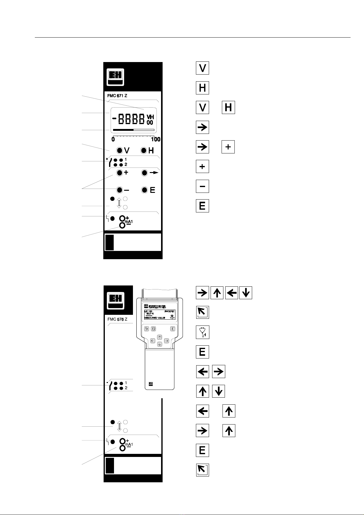
3.2 Operating elements: Silometer FMC 671 Z . . 20
3.3 Operating elements: Silometer FMC 676 Z . . 21
4 Calibration and Operation . . . . . . . 22
4.1 Commissioning of the transmitter . . . . . . 22
4.2 Empty/full calibration for level measurement . 23
4.3 Empty/full calibration for volume measurement 24
4.4 Level offset value . . . . . . . . . . . . 25
4.5 Measured value display . . . . . . . . . 26
4.6 Locking the parameter matrix . . . . . . . 26
5 Linearization . . . . . . . . . . . . . 27
5.1 Linearization for a horizontal cylindrical tank . 28
5.2 Linearization for a tank with conical outlet . . 29
5.3 Other modes . . . . . . . . . . . . . . 32
6 Analogue Outputs . . . . . . . . . . . 33
6.1 Configuration . . . . . . . . . . . . . . 34
7 Limit Switches . . . . . . . . . . . . 36
7.1 Relay settings . . . . . . . . . . . . . 37
7.2 Applications . . . . . . . . . . . . . . 38
8 Other Applications . . . . . . . . . . 41
8.1 »Dry calibration« for continuous level
measurement with Deltapilot probes . . . . 41
8.2 Level limit switching . . . . . . . . . . . 43
8.3 Continuous level measurement with separate
level limit detection . . . . . . . . . . . 46
8.4 Level measurement with automatic calibration
correction . . . . . . . . . . . . . . . 47
9 Trouble-Shooting . . . . . . . . . . . 50
9.1 Faults and warnings . . . . . . . . . . . 50
9.2 Simulation . . . . . . . . . . . . . . . 53
9.3 Exchanging transmitters or probes . . . . . 54
9.4 Repairs . . . . . . . . . . . . . . . . 55
10 Quick programming guide . . . . . . . 56
10.1 Level measurement with separate level switching,
capacitance probes . . . . . . . . . . . 56
10.2 Continuous volume measurement (linearization) 57
10.3 Level limit switching . . . . . . . . . . . 58
10.4 Level measurement with automatic calibration
correction: two capacitance probes . . . . 59
2
Silometer FMC 671 Z/676 Z Table of Contents

Notes on Safety
The Silometer FMC 671 Z/676 Z is used for continuous level measurement. The
measuring system must be installed by qualified personnel only, and in accordance with
the instructions in this manual. When using the measuring system in potentially explosive
areas, relevant local standards must be observed. Measuring specifications and safety
directives concerning the measuring points must be observed at all times.
CertificatesThe following table shows available sensors and probes and their applications.
Certificate Transmitter Notes
TÜV 00 ATEX 1640 Silometer FMC 671 Z/676 Z II (1) GD,
[EEx ia] IIC/IIB,
install outside Ex-area
PTB 98 ATEX 2215 X DC 12 TE, DC .. TE .,
DC .. E ., DC ..
Capacitance probes
11500 Z(M), 11961 (Z),
21561 (Z)
with electronic insert
EC 16/17/27/37/47 Z,
FEC 12,
HTC 16/17/27 Z, HTC 10 E,
HMC 37/47 Z
II 1/2 G, II 2 G,
EEx ia IIC/IIB T6
PTB 98 ATEX 2215 X DC 12 TE, DC .. TE .,
DC .. E ., DC ..
Capacitance probes
11500 Z(M), 11961 Z,
21561 Z
with electronic insert
EC 17/37/47 Z, FEC 12
II 1 G,
EEx ia IIC/IIB T6
PTB 98 ATEX 2094 DB 50, DB 50 L,
DB 51, DB 52, DB 53
II 1/2 G, II 2 G,
EEx ia IIC T4…T6
Z-65.13-107 DC 12 TE, DC .. TE .,
DC .. E ., DC ..
Capacitance probes
11500 Z, 11961 Z, 21561 Z
with electronic insert
EC 37/47 Z, FEC 12,
HMC 37/47 Z
FMC 470, FMC 671/672 Z,
FMX 570 Z, FMX 770,
SIF 100/110
Continuous level measurement
for overspill protection in stationary
vessels
(for storage of non-combustible,
water-polluting liquids)
DiBT No. Z-65.11-29 Silometer FMC 671 Z
electronicinsert FEB 17
DB 50...52
Continuous level measurement
for overspill protection in stationary
vessels
(for storage of non-combustible,
water-polluting liquids)
German Lloyd
GL No. 97517 HH
Silometer FMC 671 Z
Capacitance probes
electronic insert EC 37
or EC 47
electronic insert EC 17 Z
Level indication on channel 1
(EC 37 Z or EC 47 Z)
Level limit detection on channel 2
(EC 17 Z)
Suitable for unlimited use within the
rules
German Lloyd
GL No. 97510 HH
Liquiphant DL 17 Z Level indication on channel 1.
Suitable for unlimited use within the
rules
German Lloyd
GL No. 99350 HH
DB 50, 50 L, 52, 53
with electronic insert
FEB 17 / 17 P
Silometer FMC 671 Z/676 Z Notes on Safety
3

Notes on Safety
In order to highlight safety-relevant or alternate operation procedures in the manual the
following conventions have been used, each indicated by a corresponding icon in the
margin.
Note!
•A note highlights actions or procedures which, if not performed correctly, may
indirectly affect operation or may lead to an instrument response which is not
planned.
Caution!
•Caution indicates actions or procedures which, if not performed correctly, may
lead to personal injury or incorrect functioning of the instrument.
Warning!
•A warning indicates actions or procedures which, if not performed correctly, will lead
to personal injury, a safety hazard or destruction of the instrument.
Silometer FMC 671 Z/676 Z Notes on Safety
4

1 Introduction
Quick Operating GuidesThe front cover contains short instructions for the standard set-up, continuous level
measurement with capacitance probes, which is used in 80% of applications.
For Users familiar with the operating matrix of Endress+Hauser Commutec transmitters
in general and the Silometer FMC 671 Z/676 Z in particular, a Quick Operating Guide for
the most important operating modes is to be found in Chapter 10.
In this manualUsers unfamiliar with the Silometer FMC 671 Z/676 Z must read the operating instructions.
Since it is not possible to describe all applications in detail, the standard application,
continuous level measurement, has been used as the basis for the functional description.
Other applications as listed in Section 1.1 are described in Chapter 8. The instructions
are structured as follows:
•Chapter 1: Introduction;
contains general information including application, measurement
principle and functional description.
•Chapter 2: Installation;
contains hardware configuration, installation instructions.
connection diagrams and technical data for the plug-in card.
•Chapter 3: Controls;
describes operation with the front panel keys, Commulog VU 260 Z
and ZA 672.
•Chapter 4: Calibration and Operation;
tells you how to commission the Silometer for the standard
application.
•Chapter 5: Linearization;
tells you how to calibrate the Silometer to measure volume in a
horizontal cylindrical tank or a tank with a conical outlet.
•Chapter 6: Analogue Outputs;
describes in detail the setting of the 0/4…20 mA signal line.
•Chapter 7: Relays;
describes in detail the setting of the limit switches.
•Chapter 8: Other Applications;
describes the configuration of the Silometer for further applications not
covered in Chapter 4.
•Chapter 9: Trouble-Shooting;
contains a description of the self-checking system with error
messages, the simulation feature as well as instructions for
configuration on replacement of the transmitter, probe or electronic
insert.
•Chapter 10: Quick Programming Guide;
provides configuration flowcharts for the principle applications.
•Chapter 11: Index;
lists key words to help you find information quickly.
Further documentationIn addition to this manual, the following publications provide information on configuration
of the Silometer FMC 671 Z/676 Z.
•BA 028 Commulog VU 260 Z handheld terminal
•BA 054 ZA 672 Modbus Gateway
Installation of the probes, electronic inserts and accessories are described in the
documentation accompanying these articles - see text for references. When installing
probes in explosion hazardous areas the instructions included in the accompanying
probe certification must also be observed.
Silometer FMC 671 Z/676 Z Chapter 1: Introduction
5

1.1 Application
The Silometer FMC 671 Z/676 Z is designed for level measurement with a capacitance,
impedance or hydrostatic pressure probe. A second channel allows level limit detection
with a capacitance/impedance probe or vibration sensor. The applications described in
this manual are as follows:
•Continuous level measurement …Chapter 4
•Volume measurement in horizontal or conical tanks …Chapter 5
•Level limit detection …Chapter 8
•Continuous level measurement with automatic correction …Chapter 8.
Silometer transmitters may also be used for applications in explosion hazardous areas
and possess intrinsically-safe sensor circuits conforming to EEx ia IIC and IIB. A list of
certificated combinations is to be found in »Notes on Safety« preceding this chapter.
0/4...20 mA,
0/2...10V
output
Min./max.
relays
Silometer
FMC 671 Z/
676 Z
transmitter
BA063E01
Liquids
Bulk solids
Channel 1
Ex non-Ex
or
or
Fig.1.1:
Standard application with
Silometer FMC 671 Z/676 Z
➀
Capacitance probe
➁
Deltapilot S
➁Min Relays
Ex
BA063E02
➀Max
non-Ex
Fig.1.2:
Left:
Silometer FMC 671 Z with
limit switch
➀
Maximum fail-safe
➁
Minumum fail-safe
Right:
Silometer FMC 671 Z with
continuous level measurement
and limit switching
➀
Level measurement
➁
Limit switch
or
Channel 2
Level
Channel 2
Channel 1
BA063E03
Ex non-Ex
Silometer FMC 671 Z/676 Z Chapter 1: Introduction
6

1.2 Measuring system
A working system for level measurement comprises:
•Silometer FMC 671 Z/676 Z transmitter,
•Capacitance, impedance or Deltapilot S probe (hydrostatic pressure sensor)
•Electronic insert
For limit switching a capacitance, impedance or vibration probe is used.
The Silometer may operate as a stand alone unit with standard 0/4…20 mA and 0/2…10 V
output. Two relays, freely assignable to channel 1 or 2, can be used to control pumps,
valves, annuciators etc.. Alternatively, the Silometer may be controlled remotely with other
Commutec transmitters via the Rackbus as part of a process control system. In this case,
communication is controlled by a ZA 672 Modbus Gateway, see Fig 1.3, or any other ZA
67…Gateway.
VersionsThe Silometer is available in two versions:
•Silometer FMC 671 Z with display and operation via the front panel, and via
the handheld terminal Commulog VU 260 Z and Gateway ZA 67...
•FMC 676 Z for remote configuration by Commulog VU 260 Z handheld
terminal or via ZA 67…interface.
In all other respects, the two versions are identical. More details on controls and operation
can be found in Chapter 3.
BA063E04
Commutec transmitters
Rackbus
Personal
computer or
PC system
Programmable logic
controller with Modbus port
Sensors Actuators
RS-232C interface
Modbus interface
ZA 370
or
ZA 371
ZA 672
Fig. 1.3
The Silometer 671 Z/676 Z can
be used as a stand-alone unit,
or as part of a process control
system.
Silometer FMC 671 Z/676 Z Chapter 1: Introduction
7

1.3 Measuring principle
The Silometer FMC 671 Z/676 Z measures level on the basis of the capacitance and
hydrostatic measurement principles. In both cases the measured value is processed by
the electronic insert and passed on as a frequency signal.
Capacitance
measurement The probe and vessel form the two plates
of a capacitor, the total capacitance of
which can then be calculated from the
formula:
Ctot =C
1 + 2πε0εrx L pF (1)
--------------------------------
ln (D/d)
whereby
Ctot = total capacitance
C1= capacitance or feed through
ε0= dielectric constant of air (8.85)
εr= rel. dielectric constant of product
D= diameter of vessel
d= diameter of probe
L= length of probe immersed in
product in meters
For vessels with a diameter greater than 1 m, the capacitance varies by approx. 12 pF
per meter of covered probe.
Measurement in
conducting media If the product conducts, the capacitance is
determined by the thickness and properties
of the insulating material surrounding the
probe. Equation (1) applies, whereby the
variable D is now the diameter of the probe
with insulation. In this case the capacitance
varies by approx. 300 pF/m.
Measurement is independent of dielectric
constant and not affected by changes in
this variable.
Hydrostatic
measurement In an open vessel, the level is derived from
the hydrostatic pressure exerted by a
column of liquid on a probe placed at its
foot. The pressure exerted is:
p1=ρx g x h (2)
whereby
p1= hydrostatic pressure
ρ= density of the liquid
g = acceleration due to gravity
h = height of the liquid column.
At a constant density, the level is
proportional to the hydrostatic pressure.
C1
BA063E05
d
L
D
Fig. 1.4
Capacitance measurement principle
BA063E06
dConducting
product
L
D
Fig. 1.5
Measurement in conducting media
BA063E07
p1= ρx g x hh
atmospheric
pressure
p1
Fig. 1.6
Hydrostatic measurement principle
Silometer FMC 671 Z/676 Z Chapter 1: Introduction
8

1.4 Functional description
The capacitance or pressure measured by the sensor is converted into a frequency
signal by the electronic insert located in its head. The Silometer FMC 671 Z/676 Z
supplies the power and receives a level-proportional frequency signal over a two-core
cable. The signal is then processed to provide the following functions:
Silometer functions
•Level measurement
By calibrating at two levels, »empty« and »full«, level measurement can be made in
the units entered during calibration.
•Volume measurement
For non-linear volume/level relationships, volume can be calculated from level via
the vessel characteristic which describes the shape of the vessel. This function is
described under »Linearization« in Chapter 5.
•Level limit switching
Channel 2 of the Silometer can be used as a level limit switch in conjunction with a
vibration or capacitance/impedance probe.
•Level measurement with automatic calibration correction
If the dielectric constant or density of the liquid changes or is unknown, the
Silometer can be configured to provide a corrected level measurement on channel 1
by using a level switching probe at channel 2.
•Analogue output
The signal resulting from the calibration and linearisation provides a standard
0/4...20 mA and 0/2...10 V output, proportional to level or volume. Any portion of the
measuring range can be taken to provide a scaled output, see Chapter 6.
•Relay control
The two relays can be assigned to either measuring channel to provide level control
by switching pumps on and off, see Chapter 7.
•Rackbus signal
The measured values and complete configuration can be read by the ZA 672
Modbus Gateway (and ZA 67…computer interface) for integration into process
control systems and visualisation on personal computers.
•Fail-safe operation
If a fault condition is detected, e.g. a break in sensor - transmitter cable, the
analogue signal switches to –10 % or +110 % level or holds the last measured
value. In addition, each relay can be individually set to switch on or off as required.
frequency
analog
digital
current
voltage
sens. [Hz/pF]offset [Hz]
offset [pF] sens. [pF/cm]
range upper limit
V2
range lower limit
V1
frequency
electronic-
insert electronic-
insert
capacit./
pressure
volume
V2
V1level
volume
H2
H1
level
cap./press.
level zero point shift
BA063E08
Fig.1.7
Signal processing in the
Silometer FMC 671 Z/676 Z
for single channel operation
Silometer FMC 671 Z/676 Z Chapter 1: Introduction
9

2 Installation
This Chapter describes:
•The probes for use with the Silometer FMC 671 Z/676 Z
•Silometer installation in a rack or Monorack housing
•Electrical connections for the Silometer and sensors
•Hardware configuration for Commulog VU 260 Z or ZA 67…operation
•Technical data.
Warning!
•The Silometer FMC 671 Z/676 Z transmitter must be installed outside explosion
hazardous areas.
2.1 Probes
Table 2.1 lists the sensors most frequently used with the Silometer FMC 671 Z/676 Z
transmitter. In addition to those listed, all probes which can be used with an EC 17 Z,
EC 37 Z or EC 47 Z electronic insert can be connected to the transmitter. Installation hints
can be taken from the appropriate Technical Information Sheet.
Sensor constants Deltapilot probes and EC 37 Z/47 Z inserts are supplied with the sensor constants zero
frequency »fo« and sensitivity »Df« or »S«. The constants for Deltapilot S probes are in
the table on page 55; for electronic inserts, they are printed on the nameplate, see Fig. 9.1,
Section 9.3.
Note these constants and enter them into fields V3H5 and V3H6 during commissioning,
Section 4.1. This dispenses with the need for a recalibration of the transmitter on
replacement of the sensor or insert.
Principle
Channel 1 Channel 2
Probe TI sheet Insert Probe TI sheet Insert
Capacitance,
Multicap
DC 11 TI 169F
DC 16 TI 096F
DC 21 TI 208F
DC 26 TI 209F
11 322 Z E 11.81.03
11 500 Z TI 161F
21 211 E 10.73.18
TA TI 239F
TE TI 240F
E TI 242F
A TI 243F
EC 37 Z
EC 47 Z
DC 11 TI 169F
DC 16 TI 096F
DC 21 TI 208F
DC 26 TI 209F
11 450 (Z/St) TI 197F
11 961 (Z) E 04.77.04
21 262 (Z/St) TI 227F
21 265 (Z/St) TI 195F
EC 17 Z
EC 16 Z
Hydrostatic
pressure
Deltapilot
DB 50...53 TI 257F
FEB 17
(P)
Not suitable
Vibration Not suitable Liquiphant
DL 17 Z 013154-0008
FDL 30 TI 185F
FDL 31 TI 185F
Soliphant
DM 90 Z…92 Z TI 124F
BA 042F
EL 17 Z
FEL 37
EM 17 Z
Table 2.1
Selection of probes suitable
for use with the Silometer
FMC 671 Z/676 Z
Silometer FMC 671 Z/676 Z Chapter 2: Installation
10

2.2 Silometer installation
There are three possibilities for installing Silometer transmitters:
•Assembly rack for max. 12 transmitters,
•Field housing, ingress protection 65, for max.6 transmitters,
•Monorack housing for individual or series installation.
Rack installationA Racksyst system can be ordered fully wired, in which case the sensors and the external
power supply only need to be wired. Planning hints can be found in Publication
SD 041/00/en, »Racksyst Assembly Racks« .
When installing in your assembly rack, or when installing with cards from other
manufacturers, fill the rack as follows (see also Fig. 2.1):
Rack arrangement
Step Procedure
1 Allocate the power supply (NT 470) at the rightmost position.
- If two NT 470s are used, install a 2 HP dummy panel between them.
2 Install non-intrinsically safe transmitters next to the power supply.
- Install a 2 HP dummy panel between all foreign transmitters and between
Racksyst cards and foreign transmitters
3 Install intrinsically safe transmitters to the left of the rack.
- Install foreign cards first.
- Install dummy panels between all foreign transmitters and between Racksyst
cards and foreign transmitters in accordance with the instructions on the
Ex-Certificate.
- No spacer is required between Racksyst cards.
Racksyst field housingInstructions for installing Commutec transmitters in the Racksyst field housing with half
19" rack are to be found in Publication PI 003.
•Check that the field housing is not installed in direct sunlight.
- If appropriate fit a protective sun cover.
•The maximum permissible ambient temperature for the field housing varies
between +50…+60°C according to the power consumption of the cards
(0…20 W).
BA063E09
Non-E+H
(Ex)i devices E+H (Ex)i
devices E+H devices Non-E+H
devices NT power
supply
Spacing between
non-E+H (Ex)i devices
as per certificate
2 HP dummy panel between
E+H and non-E+H devices
Fig.2.1:
Recommended arrangement for
Racksyst rack assemblies
Silometer FMC 671 Z/676 Z Chapter 2: Installation
11

Monorack housing The Silometer FMC 671 Z/676 Z transmitter and Monorack housing are supplied separately.
The system must be assembled as shown in Fig. 2.2 before use.
•The Monorack is prepared for wall- or rail-mounting, degree of protection
IP 40 or IP 30 respectively.
•The site must be chosen such that the operating temperature of
–20°C…+60°C for one Monorack and –20°C…+50°C for Monorack banks is
not exceeded.
Full details of the Monorack installation procedure can be taken from the manual supplied
with it.
Monorack protective
housing If the Silometer FMC 671 Z/676 Z transmitter and Monorack housing are to be mounted
at an exposed site, then it is recommended that they be installed in the protective
housing, degree of protection IP 55, which is available as an accessory.
•The protective housing accomodates two Silometer FMC 671 Z/676 Z
transmitters.
•The permissible ambient temperature is –20°C…+50°C for one Monorack and
–20°C…+40°C for two.
Dimensions and instructions for installation are to be found in the Technical Information
sheet TI 099/00/en.
BA063E10
Plug-in card
Monorack
housing
Monorack base
(terminal block)
Retaining
screws
Retaining
flap
Fig.2.2:
Assembly and disassembly of
the Monorack housing
Power
pack
Fig. 2.3:
Monorack protective housing
Silometer FMC 671 Z/676 Z Chapter 2: Installation
12

2.3 Transmitter wiring
Warning!
•Make electrical connections with the power supply switched off!
•When wiring up probes and sensors in explosion hazardous areas, observe the
instructions on the certificate and other appropriate regulations.
Rack wiringFig. 2.4 is a pin assignment diagram for the Silometer FMC 671 Z/676 Z.
•Terminals z 30, b 14, d 14 and b 10 are connected internally
•Inputs d2, d4 and z2, z4 are electrically isolated from the circuit and each
other.
•The circuit zero of the unit ( ⊥) is connected to the negative terminal of the
supply voltage.
Note!
•Two indexing pins, at positions 1 and 22 in the rack connector ensure that Silometer
FMC 671 Z/676 Z transmitters only can be inserted at these points. The pins must
be inserted if the rack is not custom built by Endress+Hauser.
d b z
+ +
2
4
6
8
2
1EC 47 Z
d2
d4
3
2
+
-FEB 17 (P)
d2
d4
2
1
+
-EC 37 Z
d2
d4
2
1
+
-EC 17 Z
z2
z4
2
1
+
-
z2
z4
L
L+ 20 V...30 V
z30
d32
d2
d4
+
d10
b10
+
+
d12
d14 0/4...20 mA
+
+
b12
b14 0/2...10 V
z18
d20
z20
z22
d24
z24
r
u
a
r
u
a
rz26
d28
z28
u
a
+
+ +
14
16
32
EL 17 Z/EM 17 Z
z2
z4 EC 16 Z
2
1
ZA 67...
22
24
26
28
30
+
-
+
-
10
12
r
u a
18
20
r
u a
r
u a
L-
L+
Analogue
outputs
Relay ➀
Power supply
Relay ➁
Level,
volumen
Relay ➀
Relay ➁
BA063D11
Alarm relay
Non-Ex-area
Input
level
measurement
DC supply
Ex-area
Remote dialog
Deltapilot S
Current ➀
Voltage ➀
Rackbus
Capacitance/
Multicap probe
Capacitance/
Multicap probe
Multicap
Capacitance/
Multicap probe
Liquiphant or
Soliphant
Input
limit level
switching
FMC
671 Z
676 Z
Alarm relay
Fig.2.4:
Pin assignment diagram for
Silometer FMC 671 Z/676 Z
Silometer FMC 671 Z/676 Z Chapter 2: Installation
13

Rackbus For system use, wire the Rackbus as shown in Fig. 2.5.
•For ZA 672 - Computer/PLC wiring see Operating Instructions BA 054F/00/en.
•Be sure that the system is properly grounded! A difference in ground potential
between the Modbus device/personal computer serial connectors and the
ZA 672 Modbus Gateway can cause damage to the equipment or loss of
module programs.
Analogue and
relay outputs The negative pole of the 24 V DC supply voltage is connected to the negativ terminal of
the analog signals (e.g. 4/4...20 mA) and the circuit zero of the FMC 671 Z/676 Z.
•Any number of measurement and control units can be connected in parallel to
the voltage output, provided that all potentials are related to negative terminal
of the 24 V supply (RL≥10 kOhm).
•Only one non-floating device can be connected to each of the current
outputs.
•There is no limit to the number of floating devices, apart from that imposed by
considerations of maximum or minimum load, see Section 2.6.
Alarms and limit switch relays can be connected as shown in Fig. 2.6.
•Max. current per wire 2.5 A: for switching capacity see Section 2.6.
BA063E13
Max.64
Commutec
transmitters
in parallel on
Rackbus
Commutec transmitters FMB, FMC, FMU, PMX, TMT etc.
Fig.2.5:
Rackbus wiring diagram
Max. current per wire 2.5 A BA063E12
Fig. 2.6:
Suggestions for wiring together
relays and alarms
Recommended
Alternative 1
Alternative 2
Silometer FMC 671 Z/676 Z Chapter 2: Installation
14

Monorack wiringFig. 2.7 shows the layout in the base of the Monorack housing, the pin assignments
correspond to those in Fig. 2.4. When connecting together several Monoracks, follow the
instructions supplied with the housing.
•The 24 V version is supplied with a dummy card fitted at the power control
slot. Remove this and insert the 24 V card supplied.
•Insert the coding pins supplied at positions 1 and 22 in the female connector
at the base of the housing.
2.4 Probe connection
The Silometer FMC 671 Z/676 Z can be operated with a variety of probe types, each
requiring a different electronic insert. For Channel 1, continuous level measurement:
•EC 37 Z or EC 47 Z for capacitance and Multicap probes
FEB 17 (P) for Deltapilot S probes
For Channel 2, level limit switch:
•EC 17 Z for capacitance probes; EC 16 Z/EC 17 Z for Multicap probes
EL 17 Z for Liquiphant
EM 17 Z for Soliphant
Probe cable
We recommend the use of screened installation cable, max. line resistance 25 Ω/core,
for the probe / transmitter cable.
•Ground the screen at both ends (observing local regulations!)
– If this is not possible, ground the screen at the sensor end only.
– For more details send for TI 241F/00/en »EMC tests«.
•Observe explosion protection instructions!
Slot for
24 V card
(card supplied in
slot is a dummy)
BA063E14
Power
Outputs
see Fig.2.4
Channel 1, d2, d4
Insert coding
pins for
FMC 671 Z/
FMC 676 Z
version at
Positions
1 and 22
Hole for mounting
screw
Hole for mounting
screw
Channel 2, z2, z4
Fig. 2.7:
Layout of Monorack
terminal blocks
Silometer FMC 671 Z/676 Z Chapter 2: Installation
15

EC 37 Z and EC 47 Z The electronic inserts EC 37 Z and EC 47 Z have two measuring ranges which can be
selected by inserting a bridge between terminals 4 and 5 of the insert, see Fig 2.8.
Full instructions on selection of the insert are to be found in Publication TI 271F.
•Note the zero frequency fo____ and sensitivity S_____on the insert.
EC 17 Z The EC 17 Z electronic insert can be used at Channel 2 with capacitance probes for limit
level switching. The connection diagram is shown in Fig. 2.8. Technical information is
given in Publication TI 268F.
FEB 17 (P) The FEB 17/FEB 17 P electronic inserts can be used at Channel 1 with Deltapilot S probes
to measure level and volume in open vessels. The probe constants are listed in the table
on page 55.
EL 17 Z and EM 17 Z The EL 17 Z electronic inserts can be used at Channel 2 with Liquiphant for limit level
switching. For Soliphant the EM 17 Z insert is used. Publications BA 039F (013154-0008)
and BA 042F (014897-0002) contain full installation instructions.
EC 16 Z The EC 16 Z electronic insert is for use with the Multicap DC 16 probe with active build-up
compensation. Wire it up as the EC 17 Z (see TI 170F).
•The bridges 4 - 5 and 3 - 4 are not required.
1 2 3 4 5 6
EC 37 Z/47 Z
d4 d2
BA063E15
Channel 1
Insert bridge for
Range II (standard)
Remove for Range I
Ground
connection
Fig. 2.8:
Connection diagram for
electronic inserts
Left: EC 37 Z/EC 47 Z
Right: EC 17 Z
1 2 3 4 5 6
EC 17 Z
z4 z2 Insert bridge if
conductive
build-up on probe
Channel 2
Ground
connection
Insert bridge
(see instructions)
BA063E16
d4 d2
FEB 17/FEB 17 P
1234
BA063D17
Channel 1
Fig.2.9:
Connection diagram for
electronic inserts
Left: FEB 17 (P)
Right: EL 17 Z/EM 17 Z
1 2
z4 z2
EL 17 Z/EM 17 Z
Channel 2
BA063D19
Silometer FMC 671 Z/676 Z Chapter 2: Installation
16

2.5 Hardware configuration
Fig. 2.10 shows the configuration elements for remote operation of the Silometer
FMC 671 Z/676 Z transmitter.
Commulog VU 260 ZThe Silometer is supplied configured for operation with the Commulog handheld terminal,
with the hook switch connected to the contact nearest the front panel.
•If the handheld terminal is to be used during computer operation, the card
must first be reconfigured for Commulog operation
Gateway ZA 67...Configure the Silometer card for remote operation via the ZA 672 Modbus gateway
(or ZA 67…computer interface) as follows:
•Set the hook switch to ZA 672/ZA 67…operation as indicated (contact
nearest the backplane connector).
•Set a unique device address between 0 and 63 at the address switch.
- When off, each switch has the value 0.
- When on, each switch is assigned the value shown in Fig. 2.10, inset.
In the example the address is 2 + 8 = 10.
A full description of ZA 672 operation is to be found in Publication BA 054F/00/en.
Caution!
•Electrostatic discharge can degrade performance or damage electronic modules.
Touch a grounded object to rid yourself of charge before handling the modules.
Front panel
BA063E20/21
Communication via sockets at
front side: VU 260 Z (Default)
Female
multipoint
connector
Address = 2 + 8 = 10
Communication via female multipoint
connector contacts: ZA 67...
Address
switch
Communications
switch
Fig.2.10:
Configuration elements of
Silometer FMC 671 Z/676 Z
shown for Commulog operation
Silometer FMC 671 Z/676 Z Chapter 2: Installation
17

2.6 Technical data: Silometer FMC 671 Z/676 Z transmitter
Construction •Design: 19", 7 HP, plug-in card
•Front panel: black synthetic with blue field inlay, grip and markings,
Protection: IP 20 (DIN 40050)
•Dimensions: see diagram
•Weight: approx. 0.3 kg
•Operating temperature: –0°C...+70°C
•Storage temperature: –20°C...+85°C
Electrical connection •Multipoint plug: conforming to DIN 41612, Part 3, Type F (28-pole)
- FMC 671 Z/676 Z with coding pins in positions 1 and 22
•Power supply: 24 V DC (–4V…+6V); residual ripple <600 mA, 100 Hz
•Supply current: approx. 90 mA, max. 125 mA, integrated fine-wire fuse
•Signal inputs: Electrically isolated from the rest of the circuitry
Protection [EEx ia] IIC or IIB
•Probes, Channel 1: Capitance probes with EC 37 Z or EC 47 Z electronic insert
Deltapilot S DB…with FEB 17 (P) electronic insert
Channel 2: Capacitance probes with EC 17 Z or EC 16 Z electronic insert
Liquiphant DL 17 Z or Soliphant DM 90…92 Z.
•Electromagnetic Interference Emission to EN 61326; Electrical Equipment Class A
compatibility: Interference Immunity to EN 61326
Outputs •Analogue output: 0...20 mA/4...20 mA selectable, RLmax. 500 Ω
0...10 V/2...10 V selectable, RLmin. 10 k Ω
•Relays: Two independent relays each with a potential-free
change-over contact; freely selectable switching range
and hysteresis
Third relay for fault indication
Max. switching capacity: 2.5 A, 250 V AC, 300 VA
at cos ϕ> 0.7
or 100 V DC, 90 W
•Fail-safe circuit Minimum or maximum, switchable
Indication and
configuration •FMC 671 Z/676 Z: LCD and 6 buttons on front panel (FMC 671 Z only).
6 LEDs for function control, also configurable via
Commulog handheld terminal or ZA 672/ZA 67…
•FMC 676 Z: 6 LEDs for function control, also configurable via
Commulog handheld terminal or ZA 672/ZA 67…interface
Certificates •Silometer TÜV 0 ATEX 1640
FMC 671 Z/676 Z: PTB No. Ex-88.B.2048 X
BA063E22
Fig.2.11
Silometer FMC 671 Z/676 Z
plug-in card
Silometer FMC 671 Z/676 Z Chapter 2: Installation
18
This manual suits for next models
1
Table of contents
Other Endress+Hauser Tank Equipment manuals
Popular Tank Equipment manuals by other brands

Trane
Trane RSDT1000F0AA Installation, operation and maintenance

WELBA
WELBA WTS-200 Installation and operating instructions

Regulus
Regulus PS2F 3000 N25 Installation and operation manual

FFS
FFS EVO 400 Replacement guide

Vetus
Vetus ILT120B installation manual

Morrison
Morrison 915 Series Installation, operation and maintenance instructions