Gardena 4000/5 eco User manual

DE Betriebsanleitung
Hauswasserwerk
EN Operator’s manual
Pressure Tank Unit
FR Mode d’emploi
Groupe de surpression
NL Gebruiksaanwijzing
Hydrofoorpomp
SV Bruksanvisning
Hydroforpump
DA Brugsanvisning
Husvandværk
FI Käyttöohje
Painevesiyksikkö
NO Bruksanvisning
Trykktank
IT Istruzioni per l’uso
Autoclave
ES Instrucciones de empleo
Estación de Bombeo con Calderín
PT Manual de instruções
Bomba doméstica
PL Instrukcja obsługi
Zestaw hydroforowy
HU Használati utasítás
Házi vízellátó
CS Návod k obsluze
Domácí vodárna
SK Návod na obsluhu
Domáca vodáreň
EL Οδηγίες χρήσης
Πιεστικό με βαρέλι
RU Инструкция по эксплуатации
Станция бытового водоснабжения
автоматическая
SL Navodilo za uporabo
Hišna vodna črpalka
HR Upute za uporabu
Kućni hidroforska pumpa
SR/ Uputstvo za rad
BS Kućna hidroforska pumpa
UK Інструкція з експлуатації
Домова водопровідна станція
RO Instrucţiuni de utilizare
Hidrofor cu rezervor
TR Kullanma Kılavuzu
Konut Suyu Tertibatı
BG Инструкция за експлоатация
Хидрофорна уредба с
разширителен съд
SQ Manual përdorimi
Impiant uji për shtëpi
ET Kasutusjuhend
Hüdrofooriga veeautomaat
LT Eksploatavimo instrukcija
Siurblys su slėgio rezervuaru
LV Lietošanas instrukcija
Spiedtvertnes ierīce
4000/5 eco Art. 1754
5000/5 eco Art. 1755
5000/5 eco inox Art. 1756
DEENFRNLSVDAFINOITESPTPLHUCSSKELRUSLHR
SR/
BS
UKROTRBGSQETLTLV

3
I1
3
1
2
I2
Art. 1723 /
Art. 1724
4
5
6
I3
9
8
7
O1
q
Off
Man.
Auto
Start
O4
q
Off
Man.
Auto
Start
O2
0
9
e
8
O3
q
Off
Man.
Auto
Start
O5
ECO MAX
r
S1
t
9
M1
z
0
u
M2
A
B
z
u
M3
E H
9
T1
s
a
TD1
447 mm
615 mm
549 mm
294 mm153 mm
292 mm
146 mm
576 mm

7
EN
EN
Translation of the original instructions.
This product may be used under super-
vision, or if instruction regarding the safe
use of the product has been provided and
the resulting dangers have been understood, by
children aged 8 and above, as well as by persons
IMPORTANT!
Read the operator’s manual carefully before use and keep for future
reference.
Electrical safety
DANGER! Electric shock!
Risk of injury due to electric shock.
vAlways unplug your Pressure Tank Unit before filling, after operation,
when troubleshooting and before carrying out any maintenance work.
The product must be supplied through a residual current device (RCD) having
a rated residual operating current not exceeding 30 mA.
The pump must be located on solid, even ground, protected from flooding.
Take care that the pump cannot fall into water.
As an additional safety device an authorised safety switch can be used.
vPlease ask your electrician for his advice.
Data indicated on the type plate must match the technical data of the mains
supply.
The power cable as well as any extension cable must not have a smaller diameter
than rubber sheathed cables according to DIN VDE 0620 (see 8. TECHNICAL
DATA – Connection cable).
Protect the power cable from heat, oil and sharp edges.
Do not use the power cable for carrying the pump or for unplugging.
vIf the supply cord is damaged, it must be replaced by the manufacturer,
its service agent or similarly qualified persons in order to avoid a hazard.
The pump must not be used when people are in water.
In Austria
In Austria the electrical connection must satisfy the ÖVE-EM 42, T2 (2000)/1979
§ 22 to § 2022.1. This requires that pumps used for swimming pools and garden
ponds may only be powered through an isolating transformer.
vPlease ask your electrician for his advice.
In Switzerland
In Switzerland portable devices that are used outdoors must be connected
through an earth leakage circuit breaker. Mobile appliances that are used out-
doors must be connected via aresidual-current device.
General safety warnings
Risk of injury due to hot water!
If the pressure switch is defective or if the water supply on the intake
side of the pump fails, any water remaining in the pump may heat up,
generating a risk of injuries caused by hot water on leakage.
The pump is equipped with a temperature fuse, which switches off the
pump at highwater temperatures (approx. 65 °C) (orange warning lamp
lights up).
vAfter temperature-related cut-out, disconnect the pump from the
mains via the main circuit breaker, let the water cool (approx.
10 – 15 min.) and secure the water supply on the intake side before
putting into operation again.
1. SAFETY
with physical, sensory or mental disabilities or
a lack of experience and knowledge. Children
must not be allowed to play with the product.
Cleaning and user maintenance must not be per-
formed by children without supervision. The use
of this product by young people under the age of
16 is not recommended. Never operate the prod-
uct when you are tired, ill or under the influence of
alcohol, drugs or medicine.
Intended use:
The GARDENA Pressure Tank Unit is intended for private use in the house
and garden; it is not intended for operation of watering equipment and
accessories in public gardens.
Liquids pumped:
The GARDENA Pressure Tank Unit can be used to deliver rainwater, tap
water and chlorinated water.
CAUTION! The GARDENA Pressure Tank Unit is not suitable for
continuous operation (e.g. industrial use, continuous circulation
operations). Corrosive, easily combustible, aggressive or explosive
liquids (such as gasoline, petroleum or nitro thinner), saltwater
and food must not be pumped. The temperature of the liquid must
not exceed 35 °C.

EN
8
vBefore operating the pressure tank unit, first make a visual check to ensure
there is no damage to the pressure tank unit (especially regarding power cable
and plug).
A damaged pressure tank unit must not be used.
vIn case of damage, please have the pressure tank unit checked by our
GARDENA Service Centre or by an authorised electrician.
Protect the pump from rain. Do not use the pressure tank unit in a wet or moist
area.
In order to avoid dry-running of the pressure tank unit, take care that the end of
the suction hose is always submerged into the liquid.
The pressure tank unit must not be run dry nor with the stopcock in the suction
pipework closed.
vBefore each operation, fill the pressure tank unit to overflowing with approx.
2to 3 l of the liquid to be pumped!
Sand and other abrasive substances in the liquid cause increased wear and
reduce the pump’s output.
When using the pump for domestic water supply, please adhere to the local
water and sewerage regulations. In addition observe the regulations of DIN 1988.
vIf necessary contact your local water authority.
DANGER! This product makes an electromagnetic field while it operates. This
field may under some conditions interfere with active or passive medical implants.
To decrease the risk of conditions that can possibly injure or kill, we recommend
persons with medical implants to speak with their physician and the medical
implant manufacturer before you operate the product.
DANGER! Small parts can be easily swallowed. There is also a risk that the poly-
bag can suffocate toddlers. Keep toddlers away when you assemble the product.
2. INITIAL OPERATION
Installing the Pressure Tank Unit:
The installation position must be firm and dry, and permit a secure
mounting for the pressure tank unit.
vInstall the Pressure Tank Unit at a safe distance from the pumping
medium.
The pump must be installed in a location with low air humidity and suffi-
cient ventilation in the area of the ventilation slots. It must be at a distance
of at least 5 cm from the walls. No dirt contamination (e.g. sand or earth)
may be sucked in through the ventilation slots.
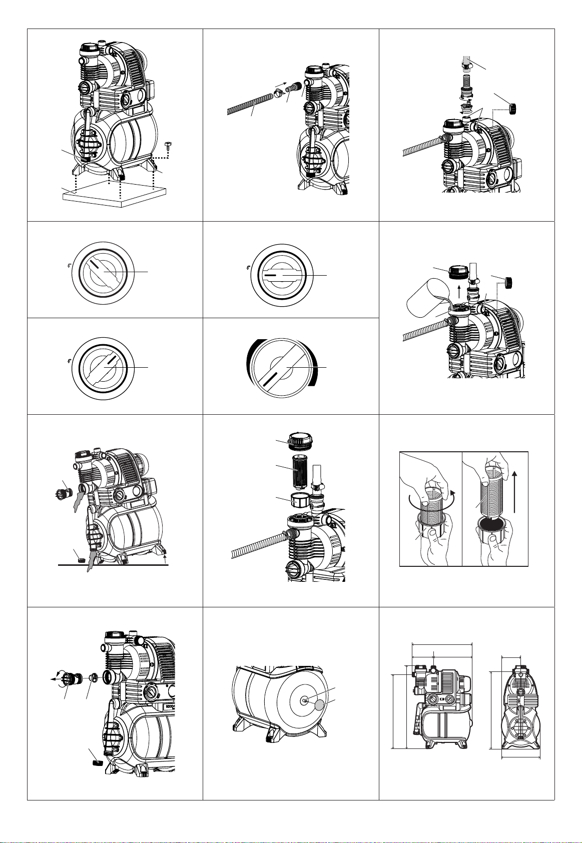
Fixed installation of the Pressure Tank Unit [Fig. I1]:
vThe Pressure Tank Unit can be screwed with all 4 feet 2onto asolid
surface 1.
Alternatively, spring mounted feet (Art. 1753-00.901.00) for low vibration
and quiet running are available as accessories via the GARDENA Service.
Install the pressure tank unit so that there is room to place asuitably sized
drainage tray under the drain screw 3to allow the unit or system to be
drained.
If possible, install the unit higher than the surface of the water to be
pumped. If this is not possible, install a vacuum-resistant valve between
the unit and the suction hose, for example for cleaning the integrated filter.
If the pump is permanently installed indoors for domestic water supply,
the Pressure Tank Unit should not be connected to the domestic water
pipework with rigid pipes but with flexible tubing, to reduce noise and to
avoid damage to the pump caused by pressure blows.
If the system is being installed permanently, please fit suitable valves on
both the intake and delivery sides. This is important e.g. for maintenance
and cleaning work or if the system is being shut down.
The connection pieces on the intake and delivery sides may only
be tightened by hand.
Connect the hose to the suction side [Fig. I2]:
A vacuum-tight suction hose must be used e.g.:
– GARDENA Suction Unit Art. no. 1411/1418/1412 or
– GARDENA Bore Hole Suction Hose Art. no. 1729.
Do not use any water hose snap connection system components on the
intake side!
v Connect the suction hose 5with the intake side
connection 6of the pump.
Connect the suction hoses 5without a threaded connector via a connec-
tion piece (e.g. Art. no. 1723/1724) 4with the intake side connection
and screw in place so that they are airtight.
To reduce the pump repriming time, we recommend using a suction hose
with backflow preventer, which prevents the suction hose emptying auto-
matically when the Pressure Tank Unit is switched off.
For suction heights exceeding 4 m also secure the suction hose 5
(e.g. by fastening it to a wooden post) to relieve the pump of the weight
of the suction hose.
If very fine dirt is present in the pumping medium, we recommend the
use of a GARDENA Pump Preliminary Filter Art. no. 1730/1731.
Connect hose to the output side [Fig. I3]:
Note:
Use pressure-tight GARDENA hoses, 19 mm (3/4") in diameter, in
connection with the GARDENA Quick-Release Threaded Connector with
33.3 mm (G1) internal thread, Art. no. 7109, and the GARDENA Suction
and High Pressure Connector, Art. no. 7120, for 19 mm (3/4") hoses
and a GARDENA Hose Clip, Art. no. 7192.
Under no circumstances use these hoses on the suction side.
1. Connect the delivery hose 7with one of the three connections 8
to the delivery side.
2. Unused pressure connections must be closed off with an end
cap 9.
Tip: With fixed piping, only assign max. 2 connections 8so that the air
can be bled off via the end cap 9of the third connection. Permanent
pipes must be laid at an ascending angle in order to allow the water to
flow back into the pump on the pressure side.
3. OPERATION
Starting the Pressure Tank Unit [Fig. O1/ O2/ O3]:
DANGER! Electric shock!
v Before filling the pump, unplug the equipment from the
mains.
CAUTION!
vFill the pump to the overflow (approx. 2 to 3 l) with water each
time before the pump is switched on.
1. Turn the rotary switch qto OFF.
2. Unscrew the cover 0of the filter chamber by hand.
3. Open an end cap 9on the delivery side to bleed off the air.
4. Open any valves in the delivery line (watering accessories, water stop,
etc.) and drain off any residual water in the delivery hose so that the air
can escape during filling and priming.
5. Slowly pour pumping medium (approx. 2 to 3 l) through the filler neck
euntil water emerges from the open delivery side connection 8.
6. Screw the filter chamber cover 0closed again, turning by hand until it
stops.
7. Close the end cap 9on the delivery side which had been ope-
ned to bleed off the air.
8. Insert the mains plug into a 230 V mains socket.
9. Turn the rotary switch qto START.The pump will start immedi-
ately!
Once priming has taken place, the rotary switch switches automatically to
AUTO and the dry-running safety is activated. Once the maximum pressu-
re is reached the pump will switch off automatically. When the pressure falls
below the minimum value due to water being drawn off, the pump will
switch on again automatically.
CAUTION!
If the pump has not started priming after 10 min.,
turn the rotary switch qto OFF.
vSee 6. TROUBLESHOOTING “The pump sucks nothing up”.
The maximum self-priming head of 8 m is only achieved if the pump is fil-
led until it overflows from the filler connection eand the delivery hose is
held high enough during self-priming so that no water can escape from
the pump via the delivery hose. It is not necessary to hold up the delivery
hose if filled suction hoses with backflow preventer are used.
Manual mode (Man.) [Fig. O4]:
When conveying very large water quantities at very low pressure, the
pump switches off in Auto mode for safety reasons. However, should this
operation be required, the pump can be operated in manual mode
(Man.)
Warning: This deactivates the dry-running safety.
v Pull the rotary switch qand turn to Man.
The pump will start.

EN
9
ECO switch [Fig. O5]:
In order to save energy (up to 15 %), the cut-out pressure on the pump
can, depending on the individual application, be regulated between ECO
and MAX (the pressure difference between ECO and MAX totals
approx. 1 bar).
v Turn the ECO rotary switch rto the required position.
Note on the use of sprinklers:
Depending on the flow rate of the sprinkler, an uneven watering pattern
may occur through the pump being switched on and off automatically.
4. STORAGE
To put into storage [Fig. S1/O1]:
If there is a risk of frost, the Pressure Tank Unit must be emptied
and stored where it will not become frozen. The product must be stored
away from children.
1. Turn the rotary switch qto OFF.
2. Unplug the mains connection for the pump.
3. Open the delivery side consumer.
4. Unscrew the end cap 9and screw out the check valve tusing
a suitable tool.
5. Tip the pump in the direction of the water outlet so that the Pressure
Tank Unit is completely drained off.
6. Store the pressure tank unit in a dry, frost-free place.
Disposal:
(in accordance with RL2012/19/EC)
The product must not be disposed of to normal household waste.
It must be disposed of in line with local environmental regulations.
IMPORTANT!
v Dispose of the product through or via your municipal recycling
collection centre.
5. MAINTENANCE
DANGER! Electric shock!
v Pull out mains plug before undertaking any maintenance.
Clean suction filter [Fig. M1/O1/M2]:
1. Turn the rotary switch qto OFF.
2. If necessary, close all the shut-off devices on the intake side.
3. Unscrew and remove cover 0of the filter chamber.
4. Draw out filter unit z u vertically upwards.
5. Hold beaker zfirmly, turn filter uanti-clockwise Aand draw out B
(bayonet fitting).
6. Clean beaker zunder running water and clean the filter ue.g. with
a soft brush.
7. Refit filter again in reverse order.
Cleaning the check valve [Fig. M3/O1]:
1. Turn the rotary switch qto OFF.
2. If necessary, close all valves on the intake side.
3. Open all pressure side outlets, so that the pressure side is
depressurised.
4. Unscrew the end cap 9and drain off the water
5. Screw out the cover tof the check valve (if applicable using asuitable
tool).
6. Remove the valve body iand wash it under running water.
7. Refit in reverse order.
8. Switch the Pressure Tank Unit back on again (see 3. OPERATION).
6. TROUBLESHOOTING
DANGER! Electric shock!
v Unplug the cable at the mains before trouble-shooting.
Work on the electrical parts must only be carried out by
GARDENA Service Centres.
Problem Possible Cause Remedy
The pump sucks nothing up Rotary switch is not turned to
START.
vRestart the pump
(see 3. OPERATION).
The pump is sucking air
through a leak at a connection
on the suction side.
vCheck all connections and
make them air-tight as
necessary.
Pump is not adequately primed
with the liquid to be pumped.
vFill the pump and ensure that
the water is able to flow
back into the pressure line
(see 3. OPERATION).
Air cannot escape on the pres-
sure side, because the pressure
side outlets are closed.
vOpen the pressure side
outlets.
End of the suction hose is not
in the water, the non-return
valve at the end of the suction
hose is missing or leaking, the
suction hose is kinked, connec-
tions are leaking or the suction
filter is blocked.
v
Check the complete suction
hose from suction point
through to the pump for leak-
tightness and repair any leaks
as necessary. Check the intake
side water supply. If applicable,
clean the suction filter.
Pump motor does not start
or stops suddenly during
operation
Mains plug not plugged in. vInsert mains plug into a mains
socket (230 V AC).
Power failure. vCheck fuse and cables.
Thermo circuit breaker
activated (orange warning
lamp lights up and the
pump housing is heated).
1. Turn the rotary switch to OFF.
2. Open consumer
(relief pressure).
3. Ensure sufficient ventilation
and allow the pump to cool for
approx. 15 min.
4. Restart the pump
(see 3. OPERATION).
The dry-running safety has
been activated (orange warning
lamp lights up).
vCheck the water supply on
the intake side and restart the
pump (see 3. OPERATION).
Water removal in Auto mode
too high. Pressure monitoring
has been activated (orange
warning lamp lights up).
vTurn the rotary switch to Man.
(Warning! Dry-running
safety is deactivated).
Pump motor runs,
but quantity delivered
or pressure fall away
suddenly
Leak on the suction side. vRepair the leak.
Too little water on intake side. vThrottle the pump on the
pressure side so that the flow
quantity on the suction side
is governed by that on the
pressure side.
Suction filter, check valve or
backflow preventer at the end of
the suction hose is blocked.
vClean the suction filter, check
valve or backflow preventer.
Pump switches on and off
too frequently Leakage on delivery side. vCheck the delivery side
for leaks and remove as
necessary.
Pressure in the boiler is too
low.
vTop up the air in the storage
tank (see below).
Boiler diaphragm is damaged. vContact GARDENA Service.
Pump switches on and off
several times before shutting
down
Installation-related fluctuations
in pressure.
vTurn ECO switch slightly
towards MAX.
Orange warning lamp
illuminates Pressure dropping below
0.8 bar during operation.
vTurn the rotary switch to
“Man” (see section entitled
“Manual mode” in the
operating instructions)
– or –
vrestart the pump (see section
3. OPERATION) and then limit
water consumption until the
pressure increases to above
0.8 bar (rotary switch will
automatically spring to
“Auto”).
Top up the air in the storage tank [Fig. T1]:
The pressure in the storage tank must be approx. 1.0 bar.
To top up the air, an air pump/tyre pump with a pressure gauge
(manometer) is required.
1. Unscrew the protective cover a.
2. Open all pressure side outlets, so that the pressure side is
depressurised.
3. Attach the air pump/tyre pump to the boiler valve sand pump air in
until the air pump/tyre pump pressure gauge shows approx. 1.0 bar.
4. Screw the protective cover aback on.

EN
10
NOTE: For any other malfunctions please contact the GARDENA service depart-
ment. Repairs must only be done by GARDENA service departments or specialist
dealers approved by GARDENA.
7. ACCESSORIES
GARDENA Suction Hoses Kink and vacuum-resistant, sold by the metre with 19 mm (3/4"),
25 mm (1") or 32 mm (5/4") diameter without fittings or in fixed
lengths Art. no. 1411/1418, complete with fittings.
GARDENA Suction Hose
Fittings For vacuum-resistant connection of the
pump to the suction hose sold by the metre. Art. 1723/1724
Suction Filter with
Backflow Preventer To equip suction hoses with Backflow
Preventer sold by the metre. Art. 1726/1727
GARDENA Pump
Preliminary Filter Recommended for pumping sandy water. Art. 1730/1731
GARDENA Bore Hole
Suction Hose For vacuum-resistant connection of the pump
to boreholes or pipe networks. Length 0.5 m.
With 33.3 mm (G1) female thread at both ends.
Art. 1729
GARDENA Spring mounted
feet (4 x) Spring mounted feet for vibration-free, quiet
running. Can be obtained via GARDENA Service. Art.
1753-00.901.00
8. TECHNICAL DATA
Pressure Tank Unit Unit Wert (Art. 1754) Wert (Art. 1755) Wert (Art. 1756)
Mains voltage /
Mains frequency V / Hz (AC) 230/50 230/50 230/50
Rated Power W 850 1100 1200
Connection cable m 1.5 H05RN-F 1.5 H07RN-F 1.5 H07RN-F
Max. delivery capacity l/h 3500 4500 4500
Max. pressure/
max. delivery head bar/m 4.5/45 5.0/50 5.0/50
Max. suction height m 8 8 8
Cut-in pressure bar 1.5 ± 0,1 1.8 ± 0,1 1.8 ± 0,1
Switch-off pressure
eco/max. bar 2.2/3.2 2.5/3.5 2.5/3.5
Perm. internal pressure
(delivery side) bar 6 6 6
Weight kg 15.0 17.0 17.0
Dimensions (L x W x H)
[Fig. TD1] cm 45 x 29 x 62 45 x 29 x 62 45 x 29 x 62
Sound power level LWA1):
measured/guaranteed
Uncertainty kWA1)
dB (A) 83 / 84
2.1 87 /88
2.1 87 /89
2.3
Measuring process complying with: 1) RL 2000/14/EG
NOTE: The stated vibration emission value has been measured according to
a standardized test procedure and can be used for comparison of one electric
power tool with another. It can also be used for preliminary evaluation of
exposure. The vibration emission value can vary during actual use of the electric power
tool.
9. SERVICE / WARRANTY
Service:
Please contact the address on the back page.
Warranty:
In the event of a warranty claim, no charge is levied to you for the services
provided.
GARDENA Manufacturing GmbH offers a two-year warranty (effective
as of the date of purchase) for this product. This warranty includes all sig-
nificant defects of the product that can be proved to be material or manu-
facturing faults. This warranty is fulfilled by supplying a fully functional
replacement product or by repairing the faulty product sent to us free of
charge; we reserve the right to choose between these options. This
service is subject to the following provisions:
• The product was used for its intended purpose as per the recommenda-
tions in the operating instructions.
• Neither the purchaser nor a third party has attempted to repair the
product.
This manufacturer’s warranty does not affect warranty entitlements against
the dealer/retailer.
If problems arise with this product, please contact our Service depart-
ment or send the defective product along with a brief description of the
fault to GARDENA Manufacturing GmbH, making sure to have sufficiently
covered any shipping costs and to have followed the relevant postage
and packaging guidelines. A warranty claim must be accompanied by
a copy of the proof of purchase.
Consumables:
The impeller and filter are wearing parts and are therefore not covered by
the warranty.
Other manuals for 4000/5 eco
4
Table of contents
Other Gardena Tank Equipment manuals