Endress+Hauser gammapilot FTG 671 User manual

gammapilot
FTG 671
Level Limit Detection
Operating Instructions
BA 082F/00/en/12.03
016309-1000
Software 1.3
Hauser
+
Endress
The Power of Know How

Short Instructions
Operation
Selects vertical matrix position
Selects horizontal matrix position
Select positon V0H0
Selects next digit
Move decimal point
Increases value of digit
Decreases value of digit
Registers entry
Function Matrix Action
Reset transmitter V9H5 ●Enter 671: see above for key functions
Press »E« to register entry
Calibrate V3H0
V3H4
V0H1
V0H2
V0H9
●Enter 5 to select standard calibration with background calibration
Press »E« to register entry
●Enter calibration date: year (3 = 93), week (01…53 )
weekday (1=Monday etc.)
Press »E« to register entry
●With vessel empty (wait 100s)
Press »E« to register entry
●With vessel full (wait 100s)
Press »E« to register entry
●With radiation off and vessel full (wait 100s)
Press »E« to register entry
Integration time V0H4 ●Enter max. permissible integration (relay switching) time in s
Press »E« to register entry (default = 7 s)
Relays (default values) …●Relay 1 is set automatically to maximum fail-safe mode
Switch-off point 38, switch-on point 72
●Relay 2 to maximum fail-safe mode
Switch-off point 72, switch-on point 38
VH
00
1
2
VH
+
E
FTG 671
Measured
value
Matrix
selection
Relay status
red: de-energised
green: energised
Parameter entry
Commulog
sockets
Alarm relay
lit: fault
Matrix position
+
+
See also »Controls«, Chapter 3
The FTG 671 transmitter and DG 57 detector must be powered up for at least 6 hours before configuration
Quick Configuration (for Cs137, DG 57) with background calibration
Gammapilot FTG 671 Short Instructions for Use

Inhaltsverzeichnis
1 Introduction . . . . . . . . . . . . . . 5
1.1 Application . . . . . . . . . . . . . . . . 6
1.2 Measuring system . . . . . . . . . . . . . 7
1.3 Measuring principle . . . . . . . . . . . . 8
1.4 Functional description . . . . . . . . . . . 9
2 Installation . . . . . . . . . . . . . . 11
2.1 Measuring system . . . . . . . . . . . . 11
2.2 Installation hints for source container and detector 12
2.3 Gammapilot installation . . . . . . . . . . 18
2.4 Transmitter wiring . . . . . . . . . . . . 20
2.5 Hardware configuration . . . . . . . . . . 24
2.6 Technical data . . . . . . . . . . . . . 25
3 Controls . . . . . . . . . . . . . . . 27
3.1 Commutec operating matrix . . . . . . . . 27
3.2 Configuration from front panel . . . . . . . 28
3.3 Configuration with Commulog VU 260 Z . . . 29
4 Calibration and Operation . . . . . . . 31
4.1 Commissioning . . . . . . . . . . . . . 31
4.2 Standard calibration with background calibration
(for detector DG57) . . . . . . . . . . . . . 33
4.3 Standard calibration (normal) without background
calibration (for DG 17 and DG 27) . . . . . . . 34
4.4 Auxiliary calibration . . . . . . . . . . . 35
4.5 Limit switches . . . . . . . . . . . . . . 36
4.6 Additional functions . . . . . . . . . . . 37
4.7 Measured value display . . . . . . . . . . 37
4.8 Locking the parameter matrix . . . . . . . 38
5 Limit Switches - Relays . . . . . . . . 39
5.1 Configuration . . . . . . . . . . . . . . 40
5.2 Acknowledgement mode . . . . . . . . . 45
6Maintenance
. . . . . . . . . . . . . 47
7 Trouble-Shooting . . . . . . . . . . . 49
7.1 Trouble-shooting tables . . . . . . . . . . 49
7.2 Fault by Gammagraphy . . . . . . . . . . 51
7.3 Simulated operating mode . . . . . . . . . 52
7.4 Exchanging transmitters and detectors . . . . 53
7.5 Repairs . . . . . . . . . . . . . . . . 54
Gammapilot FTG 671 Table of Contents
1

Gammapilot FTG 671 Table of Contents
2

Notes on Safety
Radioactive sourcesRadioactive isotopes are used as sources for level detection by gamma radiation. The
source is encapsulated in a welded, double-walled container of special steel.
•In practically all countries, the handling and operation of radioactive sources
is governed by strict regulations which are enforced by a national radiation
protection board.
•Authorisation, which usually includes a requirement for personnel specially
trained in radiation protection, must be obtained from this board before the
equipment enters the factory.
•If you are in any doubt as to the regulations in your country, call your E+H sa-
les office or representative - they will be glad to help you further!
Endress+Hauser radiometric systems are designed, manufactured and shipped with
special regard to German and International radiation safety regulations. Original radiometric
systems are normally delivered equipped with double-encapsulated sources of Cs 137 or
exceptionally Co 60, both complying with DIN 24426/ISO 2919 classification 66646. This is
acknowledged as the highest safety classification for industrial source containments.
CertificatesThe Gammapilot FTG 671 is a transmitter for level limit detection which can be used with
a variety of radioactive sources and detectors. It must be installed by qualified personnel
according to the instructions in this manual.
The transmitter and ancillary equipment are available with certificates. The Table below
indicates the combinations available and conditions for installation. Full details can be
taken from the certificates. Please note that where quoted technical data differs from that
listed in Section 2.6, that in the certificate applies.
Certificate Instruments Notes
PTB 99 ATEX 2089 Gammapilot FTG 671 II(2)G / [EEx ib] IIC,
s. Safety instructions XA 054F-C
DIBt Check Report
PA-VI 850.01
Gammapilot FTG 671 Overflow protection according to
WHG
PTB Nr. Ex-94.C.1019
ATEX 1104
DG 57-A…
DG 57-H…
DG 57-M…
EEx d ib IIC T6 / ATEX II 2 G
EEx d IIC T6 / ATEX II 2 G
EEx de IIC T6 / ATEX II 2 G
s. Safety instructions XA 057F-A
DMT 01 ATEX E 093 DG 57-D... ATEX II 2 D IP 65 T 60°C
s. Safety instructions XA 112F-A
PTB Report 6.62-1972/1
PTB Report 6.62-1972/2
PTB Report 6.32-2005
QG 020
QG 100
QG 2000
Report on local dosage
measurement on source container
Gammapilot FTG 671 Notes on Safety
3

Safety conventions
In order to highlight safety-relevant or alternate operation procedures in the manual the
following conventions have been used, each indicated by a corresponding icon in the
margin.
Note!
•A note highlights actions or procedures which, if not performed correctly, may
indirectly affect operation or may lead to an instrument response which is not
planned.
Caution!
•Caution indicates actions or procedures which, if not performed correctly, may lead
to personal injury or incorrect functioning of the instrument
Warning!
•A warning indicates actions or procedures which, if not performed correctly, will
lead to personal injury, a safety hazard or destruction of the instrument
Gammapilot FTG 671 Notes on Safety
4

1 Introduction
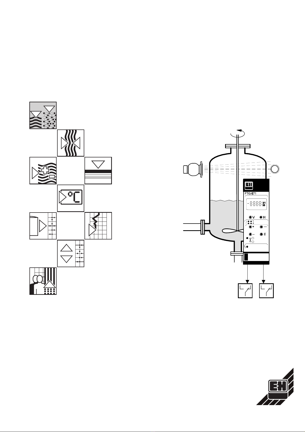
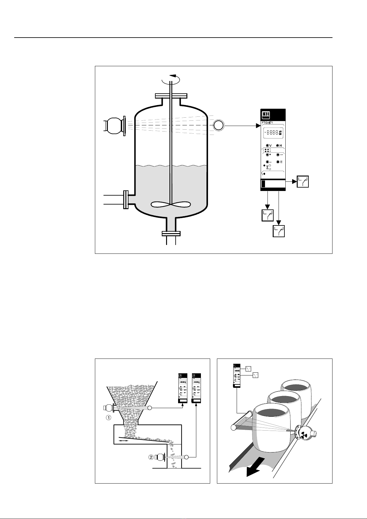
Short instructionsThe front cover contains short instructions for the standard set-up, level limit detection
with two limit relays, using the FTG 671, DG 57 and Cs 137 source.
In this manualUsers unfamiliar with the Gammapilot FTG 671 must read the operating instructions
which are structured as follows:
•Chapter 1: Introduction;
contains general information including application, measurement
principle and functional description.
•Chapter 2: Installation
contains instructions on the installation of the radioactive source,
Geiger-Müller and scintillation counters, Gammapilot FTG card,
hardware configuration, connection diagrams and technical data
for the plug-in card.
•Chapter 3: Controls;
describes operation with the front panel keys, Commulog VU 260 Z
and ZA 67…gateways.
•Chapter 4: Calibration and Operation;
tells you how to commission and operate the Gammapilot for level
limit detection.
•Chapter 5: Limit Switches;
describes in detail the setting of the relays for fail-safe or
acknowleged operation.
•Chapter 6: Trouble-Shooting;
contains a description of the self-checking system with error
messages, the simulation feature as well as instructions for
configuration on replacement of the transmitter, source or detector.
•Index lists key words to help you find information quickly.
Further documentationIn addition to this manual, the following publications provide information on configuration
of the Gammapilot FTG 671.
•BA 028 Commulog VU 260 Z handheld terminal
•BA 054 ZA 672 Modbus Gateway
•BA 073 ZA 673 Profibus Gateway
•BA 085 ZA 674 FIP Gateway
The installation of the radioactive source and detector is described in the documentation
accompanying these articles as well as briefly in Chapter 2.
•TI 264F Source Container QG 020/100
•TI 346F Source Container QG 2000
•TI 180F Scintillation Detectors DG 57
•TI 197F Geiger-Müller counters DG 17 and DG 27
When installing detectors in explosion hazardous areas the instructions included in the
accompanying certification must also be observed.
Gammapilot FTG 671 Chapter 1: Introduction
5

1.1 Application
The Gammapilot FTG 671 is designed as a
•non-contact, level limit switch
for containers (mixers, reactors, hoppers, silos, tanks) e.g. with inflammable, poisonous
and aggressive bulk material and liquids. It is also suitable for applications in the food
processing industry, e.g. on product filling lines.
Gammapilot transmitters may also be used for applications in explosion hazardous
areas, e.g. in acid tanks, boilers, cement silos, etc., and possess intrinsically-safe sensor
circuits conforming to EEx ib IIC. A list of certificated combinations is to be found in
»Notes on Safety« preceding this chapter.
Min./max.
relays
Gammapilot
FTG 671
transmitter
BA082E01
Source Detector
Alarm relay
Fig. 1.1:
Standard application showing
Gammapilot FTG 671, source
and detector
Maximum
level
detection BA082E02
Minimum
level
detection
Fig. 1.2:
Left:
Conveying limestone
Gamma radiation barriers control
the drying process
Right:
Automatic filling of beer barrels
The level is checked as the
barrels move past the barrier
FTG 671
Vibration
channel
Feed rate
1 barrel/2s Full move forward
Half full are
rejected
BA082E03
FTG 671 Filling
station
Gammapilot FTG 671 Chapter 1: Introduction
6

1.2 Measuring system
A working system for limit level detection comprises:
•Gammapilot FTG 671 transmitter,
•QG 020 or QG 100 source container with Co 60 or Cs 137 gamma source
•DG 17 or DG 27 Geiger-Müller counter or
DG 57 scintillation counter.
The Gammapilot may operate as a stand-alone or system unit. Two relays act as freely
programmable limit switches which can be operated in fail-safe or acknowledgement
mode. An alarm relay monitors the correct functioning of the measurement point and
trips on fault condition.
If controlled remotely with other Commutec transmitters within a process control system,
the Gammapilot is addressed via the Rackbus. In this case, communication is controlled
by a ZA 67…Gateway which converts Rackbus data into the appropriate network
protocol. The Gammapilot can be remotely configured, its measured data and status
scanned and its settings up and downloaded through the Gateway.
BA082E41
Detector and source container
in hazardous area
FTG 671 in safe
area
Fig. 1.3:
Gammapilots FTG 671 row
mounted in Monorack II
housings
BA082E04
Commutec transmitters
Rackbus
Personal
computer or
PC system
Programmable logic
controller with Modbus port
Sensors Actuators
RS-232C interface
Modbus interface
ZA 370
or
ZA 371
ZA 672
Fig. 1.4:
The Gammapilot FTG 671 can
be used as part of a process
control system.
Here it is shown with other
Commutec transmitters and the
ZA 672 Modbus Gateway
Gammapilot FTG 671 Chapter 1: Introduction
7

1.3 Measuring principle
Gamma ray absorption When Gamma radiation penetrates a material, it is absorbed to a degree dependent
upon the density ρ, and thickness d of the material as well as the linear absorption factor
µ, which is also dependent on the material and source. The attenuation Fsis given by:
Fs= e−µ • ρ•d
The radiation also decreases with the square of the distance between source and
detector. For limit switching µ, ρ, and d are constants and the detected radiation level
depends upon the presence or not of material in the beam. The countrate is at a maximum
when the beam is completely free and at a minimum when the all radiation has to travel
through the material. The maximum and minimum countrates Nmax and Nmin are obtained
when the transmitter is calibrated. Their dependency is given by:
Nmin =N
max/Fs= Nmaxe−µ • ρ • d
The FTG 671 output is normalised to produce the end values 0 and 100, relay 1 trips at
38 in minimum and relay 2 at 72 in maximum fail-safe mode (10 and 90 for DG 17/27 (Z)
detectors). The detection band is dependent upon the orientation of the detector, which,
however, is usually mounted horizontally on the vessel.
Statistical assessment The precision of a gamma limit switch is dependent on the statistical variation in
countrate. Since the emission of gamma rays from a radioactive source is a random
phenomenom, several successive countrate measurements taken over a given period
of time will be seen to vary randomly about a mean value. The degree of variation between
measurements depends upon the time interval chosen. The measurement precision
depends on the confidence level - 1σ, 2σor 3σ - which is to be attained. For a countrate
of N pulses per second:
±1σ = ±1√N 68.28% confidence level
±2σ = ±2√N 95.45% confidence level
±3σ = ±3√N 99.74% confidence level
Normally a confidence level of 2σis used. The statistical variation is reduced by
increasing the sampling or integration time τ:
Statistical variation = ±2√N
√τ
Barrier covered
Statistical fluctuation
in countrate Residual and
background radiation
BA082E05
Radiation
progressively
absorbed by product
Barrier free
Nmax
Nmin
Detection band
0
100
Display
Detector
Fig. 1.5:
Operating principle of FTG 671
radiometric level limit switch
Gammapilot FTG 671 Chapter 1: Introduction
8

1.4 Functional description
The Gammapilot FTG 671 has been realised as a second generation 19" Racksyst card
with Rackbus connection. It can be configured by the front panel keys, via a Commulog
VU 260 Z handheld terminal, or remotely via a ZA 67…Gateway. The transmitter can be
operated in the following modes:
•Limit switching with two relays using a DG 17/27 Geiger-Müller counter
•Limit switching with two relays using a DG 57 scintillation counter
Input circuitThe intrinsically safe input circuit of the Gammapilot FTG 671 is electrically isolated from
the rest of the circuitry by a DC/DC converter. The Gammapilot supplies power to the
detector and receives from it a frequency signal proportional to the countrate. Provision
is made for the connection of either a Geiger-Müller or a scintillation counter: the detector
type is set during configuration. For DG 57 detectors, sensor data is supplied in a
separate EPROM (DAT) which must be installed in the FTG 671 during commissioning.
RelaysThe transmitter evaluates the incoming signal and switches the level limit relays accor-
dingly. The switching status of each is indicated on the front panel. The functioning of
the relays depends upon the input signal and fail-safe mode configured in the operating
matrix. Correct configuration ensures that the relays always operate in the desired
fail-safe mode:
•Minimum fail-safe mode:
The relay de-energises and the appropriate red LED lights when the switch-
off point is dropped below, an alarm is detected or the power supply fails
•Maximum fail-safe mode:
The relay de-energises and the appropriate red LED lights when the switch-
off point is exceeded, an alarm is detected or the power supply fails.
A switching hysteresis is obtained by entering a second switch point. Alternatively the
relays can be operated in acknowledgement mode, whereby they de- or re-energise only
after confirmation in the appropriate matrix field.
Function monitoringTo increase operational safety, the Gammapilot monitors itself for correct function. If a
fault is detected, the red alarm LED lights and the alarm and limit relays de-energise. An
error code can be read from the operating matrix. A fault is detected e.g. when no input
signal is present and when the detector or the input circuit is defective.
The transmitter is also equipped with several automatic protection mechanisms which
ensure that the limits are plausible and do not drift. The reduction in countrate due to
natural decay is corrected for daily, if limits are changed, the switch points are checked
for plausibility and when the source is too weak for correct switching a corresponding
warning is given when the DG 57 detector is in use. The user can now increase the
intergration time, increase the distance between the relay switch points or a new source
must be ordered. Despite the warning, the FTG 671 will continue to measure until the
new source arrives.
CommunicationMeasured values, events and status as well as the complete transmitter configuration
can be read from the communication sockets on the front panel by a Commulog VU 260 Z
handheld terminal or over the Rackbus by a remote controller operating through a
ZA 67…Gateway. The green communication LED lights when data are exchanged. The
switch-over from local to remote configuration via Rackbus is made automatically by
disconnecting the Commulog VU 260 Z from the communication sockets.
Gammapilot FTG 671 Chapter 1: Introduction
9

Gammapilot FTG 671 Chapter 1: Introduction
10

2 Installation
This Chapter describes the:
•Measurement system
•Installation hints for source container and detector
•Gammapilot installation in a rack or Monorack housing
•Transmitter and detector wiring
•Hardware configuration of the Gammapilot card
•Technical data of the Gammapilot FTG 671 card.
2.1 Measuring system
Table 2.1 lists the sources and detectors used with the Gammapilot FTG 671 transmitter
together with the appropriate data sheets. In addition, each source container is supplied
with an instruction sheet which describes:
•How to switch on the radiation
•How to switch off the radiation
•How to change the radiation source
These must be read before the measuring system is commissioned. Section 2.2 also
includes a short description of the standard components with hints on correct installation.
Special versions of the source container are always accompanied by their own
documentation.
Source container Technical
Information,
Operating manual
Detector Technical
Information,
Operating manual
QG 020/100
QG 2000
TI 264F/00/en
TI 346F/00/en
BA 223F/00/en
Scintillation counter
DG 57
TI 180F/00/en
Geiger-Müller counters
DG 17
DG 27
TI 197F/00/en
Table 2.1:
Source container and detectors
for limit detection by gamma
radiation
Gammapilot FTG 671 Chapter 2: Installation
11

2.2 Installation hints for source container and detector
Warning!
•All activities such as mounting, dismounting and exchange of the source or detector
must be done by specially trained staff or radiation protection officials only, under
strict observance of the governing rules and regulations.
•When equipment is being installed in explosion hazardous areas, observe the in-
structions on the certificates accompanying the equipment as well as your local ru-
les and regulations.
Source Radiometric systems are normally equipped with double-encapsulated 137Cs or excep-
tionally 60Co sources complying to DIN 24426/ISO 2919 classification 66646. This is
acknowledged to be the highest safety classification governing industrial source con-
tainments.
Source Container The gamma rays emitted by the radioactive source radiate equally in all directions. In
level measurement, however, only that radiation which travels through the vessel is
required. All radiation in other directions is unwanted and must be shielded off. For this
reason, the capsule containing the source is located in the source container, ensuring
that unattenuated radiation can be emitted in the required direction only.
free height to take off
the cap
BA082E06
Radiation emission angle 5o, 20ooder 40o
Fig.2.1:
Source container
QG 020/QG 100
Standard design
BA082E68
Fig.2.2:
Source container
QG 2000
Standard design
Gammapilot FTG 671 Chapter 2: Installation
12

The shielding material is lead in a welded steel housing. Fire proof source containers are
available, which ensure that the radiation source and lead shielding cannot be lost when
the housing is heated above the melting point of lead (327 °C/620 °F); e.g. in case of
fire. The position of the radiation exit channel is marked in the dimensional drawing and
on the container, and must be taken into account when planning and mounting.
The source containers are available with manual or pneumatic ON/OFF-switching. The
QG 2000 can be obtained in a version with proximity switches for remote display of the
switching status.
Additionally, QG 20 and QG 100 are available in Euro/Swedish and Chemical design for
special safety requirements.
Attenuation factor
The attenuation factor Fsand the number of half-value layers for the different source
containers with 60Co and 137Cs sources are summarized in the following table.
From these values one may calculate:
•The
local dose rate D
at a given distance
r
from the source container (more preci-
sely: from the source in the interior of the container).
•The radius
r
of the
control area
. At this radius the local dose rate is attenuated to a
given value
D
.
The following table summarizes some typical examples:
For 137Cs in the QG 2000 the local dose rate at the surface of the container is below the
given value. Therefore, no control area is present in these cases.
K = 357 µSv m2/ h GBq (= 13.200 µSv m2/ h Ci) for 60Co
K = 96 µSv m2/ h GBq (= 3.550 µSv m2/ h Ci) for 137Cs
F
S
for 60Co
F
S
for 137Cs
QG 020 37 (5,2 HWS) 194 (7,6 HWS)
QG 100 181 (7,5 HWS) 1448 (10,5 HWS)
QG 2000 4096 (12 HWS) 8.389.000 (23 HWS)
Table 2.2:
Attenuation factors F
S
and the number of
half value layers (HWS)
D
=
K
A
r
2
F
S
D : Local dose rate [µSv/h]
r
: Distance from source (control area) [m]
A
: Activity of the source [GBq]
F
S
: Attenuation factor
(s. above table)
r
=√
KA
/
DF
S
Equation 2.1:
Calculation of the
local dose rate and the
control area
Source
container Activity
[GBq]
60Co
D = 7,5
µSv/h
60Co
D = 2,5
µSv/h
137Cs
D = 7,5 µSv/h
137Cs
D = 2,5 µSv/h
QG 020 0,74 0,98 m 1,69 m 0,22 m 0,31 m
QG 100 3,7 0,99 m 1,71 m 0,18 m no
control area
QG 2000 11 0,36 m 0,62 m no
control area
no
control area
Table 2.3:
Control area of the
Source containers by
different activitys from
60
Co and
137
Cs
Gammapilot FTG 671 Chapter 2: Installation
13

Activity of the source Endress+Hauser radiometric systems operating with the DG 57 rod scintillation counters
utilize the lowest source strengths.
For limit switching, the source strength is calculated such that the dose rate arriving at
the detector is:
•approx. 0.1…1 µSv/h (0.01…0.1 mR/h) for DG 57 detector
•approx. 1.2…8 µSv/h (0.12…0.8 mR/h) for DG 17 Z detector
•approx. 0.6…4 µSv/h (0.06…0.4 mR/h) for DG 27 Z detector.
In this case, the dose rate usually lies below that defining a control area, i.e. 7.5 µSv/h
(0.75 mR/h) or 2.5 µSv/h (0.25 mR/h), which has to be sealed off.
Warning!
•The actual extent of the control area depends on local regulations (other limits may
apply) and must be determined on the basis of dose rate measurements made on
site on both sides of the measuring system prior to the commissioning of the
equipment.
•If the front of the source container can be accessed, shielding or other protective
measures must be provided to prevent accidental exposure to the beam!
Gammapilot FTG 671 Chapter 2: Installation
14

Detector DG 57
The use of a rod scintillator for detection of the gamma rays allows the lowest source
strengths to be used for limit switching. The heart of the DG 57 is a cylindrical rod 48 mm
in diameter made of transparent synthetic scintillation material. For limit detection a length
of 100 mm or 400 m is used. For hot environments (> 40°C) it is recommended that the
version with a water-jacket is used (flowrate 40-200 l/h; max. water temperature 40 °C;
water pressure 4-6 bar).
The detector generates a pulse code modulation signal which is sampled by the FTG
transmitter at intervals of 500ms. Prior to each sampling cycle a light pulse generated
by a LED is sent through the scintillator to generate a reference value. The reference
value, temperature and pulse rate are transmitted digitally via a two-wire connection to
the transmitter FTG 671.
BA082D08
Scintillation rod produces flashes
when gamma radiation impinges
on it
Connection to FTG 671 Outer stainless steel encapsulation
Photomultiplier
Detector head
varies according to
version
Temperature
sensor
Reference diode
Fig.2.3:
Function of the DG 57 rod
scintillation counter
Overall lenght B = A + 673 ±5
Measuring lenght A
Ø 110
Ø 80
approx 500 100
144
1
12
A = /100 /400
BA082E55
110
Fig.2.4:
Dimensions in mm
Detector DG 57
Ø 108
20 120
approx 500
177
125
12
Overall lenght B = A + 682 ±3
Measuring lenght A
A = /100 /400
BA082E44
Fig.2.5:
Dimensions in mm
Detector DG 57 with
water jacket
Gammapilot FTG 671 Chapter 2: Installation
15

Detector DG 17, DG 27 The Gammapilot FTG can also be connected to a DG 17/DG 27 Geiger-Müller counter.
In this counter each gamma quantum causes a cascade of ions which are registered by
the counter as a current pulse. The electronics process the pulses and pass a countra-
te-proportional frequency signal on to the FTG 671.
Four different Geiger-Müller counters are available, see Table 2.2. The detectors can be
fitted with a water jacket for use in hot surroundings. Similarly a flange or clamps are
available for mounting. The explosion protection is: DG 17, DG 27 - none
Ø65
BA082D09
Ions created by gamma rays move to
anode and cathode causing a current
to flow
Gas filled envelope with high voltage drop Anode
Cathode
Fig.2.6:
Function of the DG 17/27
Geiger-Müller counter
Detector types DG 17 DG 27
Number of counter tubes One Two
Dose rate range
(lateral mounting)
7…60 pA/kg =
1,2…8 µSv/h (0,12…0,8 mR/h)
3,5…30 pA/kg=
0,6…4 µSv/h (0,06…0,4 mR/h)
Dose rate range
(frontal mounting)
14…120 pA/kg =
2,4…16 µSv/h (0,24…1,6 mR/h)
7…60 pA/kg
1,2…8 µSv/h (0,12…0,8 mR/h)
Table 2.4:
Geiger-Müller counter
versions
86.8
Position of detector
DG 17 DG 27
water jacket
in
out
ca. 140
ca. 280
200
20
Ø18
Ø220
DN 100 PN 16
Ø98
258
Ø180
20
Ø18
Ø220
8,4
119,6
Ø96
278
ca.296
Ø180
BA082D48
8,4
Fig.2.7:
Dimensions in mm
Geiger-Müller counters
DG 17/27
DG 17 with mounting
flange
Gammapilot FTG 671 Chapter 2: Installation
16

Mounting and installation
The QG …source container and DG…Z detector are mounted diametrically opposite
each other at each side of the vessel.
•The detector is normally mounted horizontally
•The source and detector must be exactly aligned.
•For the DG 57, the beam must be aligned to fall into the area between the two
gold strips on the detector which indicate the measuring zone (or length), for
the DG 17/27 on the marking.
The QG…source container may be bolted onto a mounting pipe or the tank with an
appropriate counterflange or onto e.g. a steel frame. Where the construction allows
access to the front of the source container, appropriate protective measures must be
taken to prevent accidental exposure.
Using the clamps supplied, the DG 57 detector must be clamped directly to the vessel
or a steel frame. DG 17/DG 27 Geiger-Müller counters can in addition be bolted to a
flange. Here it is also possible to mount the detector so that only the front face is
irradiated. For limit value detection with the DG 57, the radiation levels at the detector
side are usually so low that no control area exists. This must, however, be checked with
a dosimeter during commissioning. Fig 2.8 shows mounting examples for common
applications.
BA082D11
Standard application
Installation for two limits
Installation for strong vibrations or
high temperature
Installation on small diameter pipes (top view)
➀
➁
Fig.2.8:
Mounting examples for common
applications
Gammapilot FTG 671 Chapter 2: Installation
17

2.3 Gammapilot installation
Gammapilot transmitters must be installed outside hazardous areas, whereby three
possibilities for mounting exist:
•Standard 19" rack with space for 12 7HP cards,
•Field housing with space for up to 6 7HP cards,
•Monorack II housings for single transmitters.
Rack installation A Racksyst system can be ordered fully wired, in which case the detectors and the
external power supply only need to be connected. Planning hints can be found in
Publication SD 041F, »Racksyst Assembly Racks«. For non-Racksyst installations and
for installations including non-Racksyst cards, fill the rack as follows (see also Fig. 2.9):
Rack arrangement Step Procedure
1 Allocate the power supply (NT 470/471) at the rightmost position.
- If two NT 470s are used, install a 2 HP dummy panel between them.
2 Install non-intrinsically safe transmitters next to the power supply.
- Install a 2 HP dummy panel between all foreign transmitters and between
Racksyst cards and foreign transmitters
3 Install intrinsically safe transmitters to the left of the rack.
- Install foreign cards first.
- Install dummy panels between all foreign transmitters and between Racksyst
cards and foreign transmitters in accordance with the instructions on the
Ex-Certificate.
- No spacer is required between Racksyst cards.
Racksyst field housing Instructions for installing Commutec transmitters in the Racksyst field housing with half
19" rack are to be found in Publication PI 003.
•Check that the field housing is not installed in direct sunlight.
- If appropriate fit a protective sun cover.
•The maximum permissible ambient temperature for the field housing varies
between +50…+60 °C according to the power consumption of the cards
(0…20 W)
For EMC reasons we advise you to use special guide rails with metal clips when the
plug-in card is installed in the field housing or subrack. This connents the instrument
input filter to the subrack potential.
BA082D12
Non-E+H
(Ex)i devices E+H (Ex)i
devices E+H devices Non-E+H
devices NT power
supply
Spacing between
non-E+H (Ex)i devices
as per certificate
2 HP dummy panel between
E+H and non-E+H devices
Fig.2.9:
Recommended arrangement
for Racksyst rack assemblies
Gammapilot FTG 671 Chapter 2: Installation
18
Other manuals for gammapilot FTG 671
1
Table of contents
Other Endress+Hauser Tank Equipment manuals
Popular Tank Equipment manuals by other brands

Trane
Trane RSDT1000F0AA Installation, operation and maintenance

WELBA
WELBA WTS-200 Installation and operating instructions

Regulus
Regulus PS2F 3000 N25 Installation and operation manual

FFS
FFS EVO 400 Replacement guide

Vetus
Vetus ILT120B installation manual

Morrison
Morrison 915 Series Installation, operation and maintenance instructions